Download as PDF, PPTX
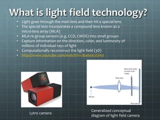
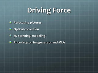
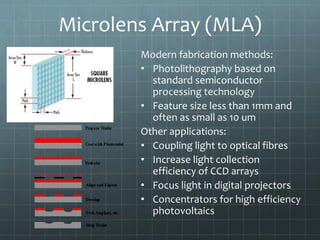
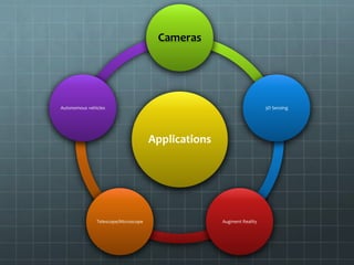
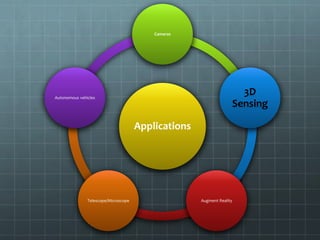
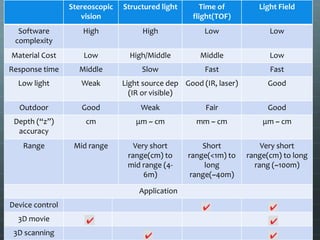

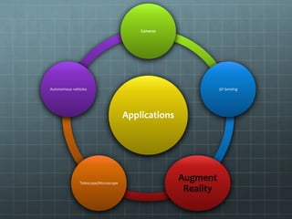
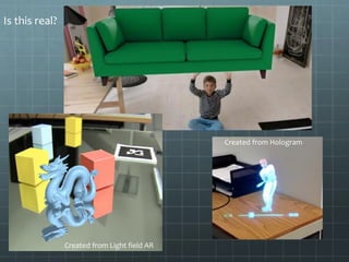
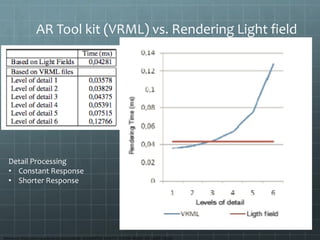
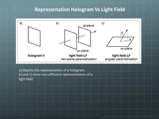
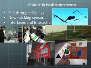
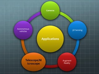
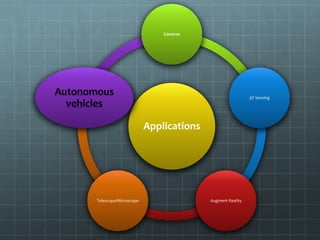
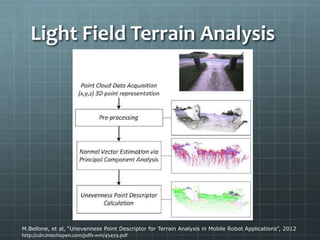
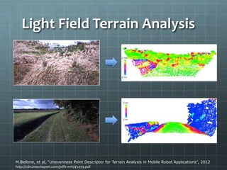
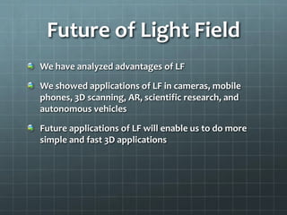

Light field technology captures and reconstructs 3D data by using a micro-lens array to gather information on light rays' direction, color, and luminosity. Its applications span across various domains including 3D sensing, augmented reality, and autonomous vehicles, offering advantages like depth imaging and enhanced visualization. Future advancements could further simplify and accelerate 3D applications, expanding its utility across multiple sectors.


![ITFT Media- AIDA Theory of advertising ppt [read only]](https://cdn.slidesharecdn.com/ss_thumbnails/aidatherypptread-only-140426013023-phpapp02-thumbnail.jpg?width=640&height=640&fit=bounds)


![[NDC19] 모바일에서 사용가능한 유니티 커스텀 섭스턴스 PBR 셰이더 만들기](https://cdn.slidesharecdn.com/ss_thumbnails/ndc19unitycustomsubstancepbrshadermadumpa-190506140539-thumbnail.jpg?width=640&height=640&fit=bounds)


