Download as PDF, PPTX


![WORKSHOP AT NAIST, AUGUST 2014
ARXIV E-PRINTS, ARXIV:1512.05471 [CS.HC], 13 PAGES
HTTP://ARXIV.ORG/ABS/1512.05471](https://image.slidesharecdn.com/16idw-161207022929/75/Keynote-at-23rd-International-Display-Workshop-7-2048.jpg)

![TRUE AR: HOW?
MANIPULATING
ATOMS
MANIPULATING
PERCEPTION
CONTROLLED
MATTER
PERSONALIZED AR IMPLANTED ARSURROUND
AR
There have been a number of shape displays based on pin
architecture. The FEELEX project [14] was one of the early
attempts to design combined shapes and computer graphics
displays that can be explored by touch. FEELEX consisted
of several mechanical pistons actuated by motors and cov-
ered by a soft silicon surface. The images were projected
onto its surface and synchronized with the movement of the
pistons, creating simple shapes.
Lumen [32] is a low resolution, 13 by 13-pixel, bit-map
display where each pixel can also physically move up and
down (Figure 4). The resulting display can present both 2D
graphic images and moving physical shapes that can be
observed, touched, and felt with the hands. The 2D position
sensor built into the surface of Lumen allows users to input
commands and manipulate shapes with their hands.
Other related project are PopUp and Glowbits devices [18,
33]. PopUp consists of an array of rods that can be moved
up and down using shape memory alloy actuators. The
PopUp, however, does not have a visual and interactive
component. Glowbits by Daniel Hirschmann (Figure 3) is a
2D array of rods with attached LEDs; the motorized rods
can move up and down and LEDs can change their colors.
Discussion
We have overviews a number of reasons why actuation can
be used in user interfaces. We summarize them in Table 1.
Applications Examples
Figure 2.7: Hand-fixed reference frame: Augmentations move w
example shows a user discussing a virtual map wit
map from di↵erent angles, he can pick it up from t
his belt and put it in his hand.](https://image.slidesharecdn.com/16idw-161207022929/75/Keynote-at-23rd-International-Display-Workshop-11-2048.jpg)
![There have been a number of shape
architecture. The FEELEX project [14
attempts to design combined shapes a
displays that can be explored by touc
of several mechanical pistons actuate
ered by a soft silicon surface. The i
onto its surface and synchronized wit
pistons, creating simple shapes.
Lumen [32] is a low resolution, 13
display where each pixel can also ph
down (Figure 4). The resulting displa
graphic images and moving physica
observed, touched, and felt with the h
sensor built into the surface of Lumen
commands and manipulate shapes wit
Other related project are PopUp and
33]. PopUp consists of an array of ro
up and down using shape memory
PopUp, however, does not have a
component. Glowbits by Daniel Hirsc
2D array of rods with attached LED
can move up and down and LEDs can
Discussion
We have overviews a number of reas
be used in user interfaces. We summa
SACHIKO KODAMA. PROTRUDE, FLOW. ACM
SIGGRAPH 2001 ART GALLERY.
HTTP://PIXIEDUSTTECH.COM
CONTROLLED MATTER
HTTP://TANGIBLE.MEDIA.MIT.EDU/
PROJECT/INFORM](https://image.slidesharecdn.com/16idw-161207022929/75/Keynote-at-23rd-International-Display-Workshop-12-2048.jpg)
![SURROUND VS. PERSONALIZED AR
MANIPULATING
ATOMS
MANIPULATING
PERCEPTION
CONTROLLED
MATTER
PERSONALIZED AR IMPLANTED ARSURROUND
AR
There have been a number of shape displays based on pin
architecture. The FEELEX project [14] was one of the early
attempts to design combined shapes and computer graphics
displays that can be explored by touch. FEELEX consisted
of several mechanical pistons actuated by motors and cov-
ered by a soft silicon surface. The images were projected
onto its surface and synchronized with the movement of the
pistons, creating simple shapes.
Lumen [32] is a low resolution, 13 by 13-pixel, bit-map
display where each pixel can also physically move up and
down (Figure 4). The resulting display can present both 2D
graphic images and moving physical shapes that can be
observed, touched, and felt with the hands. The 2D position
sensor built into the surface of Lumen allows users to input
commands and manipulate shapes with their hands.
Other related project are PopUp and Glowbits devices [18,
33]. PopUp consists of an array of rods that can be moved
up and down using shape memory alloy actuators. The
PopUp, however, does not have a visual and interactive
component. Glowbits by Daniel Hirschmann (Figure 3) is a
2D array of rods with attached LEDs; the motorized rods
can move up and down and LEDs can change their colors.
Discussion
We have overviews a number of reasons why actuation can
be used in user interfaces. We summarize them in Table 1.
Applications Examples
Figure 2.7: Hand-fixed reference frame: Augmentations move w
example shows a user discussing a virtual map wit
map from di↵erent angles, he can pick it up from t
his belt and put it in his hand.
LIGHT FIELD DISPLAYS:
PERCEIVABLE
SUBSET
FULL](https://image.slidesharecdn.com/16idw-161207022929/75/Keynote-at-23rd-International-Display-Workshop-14-2048.jpg)
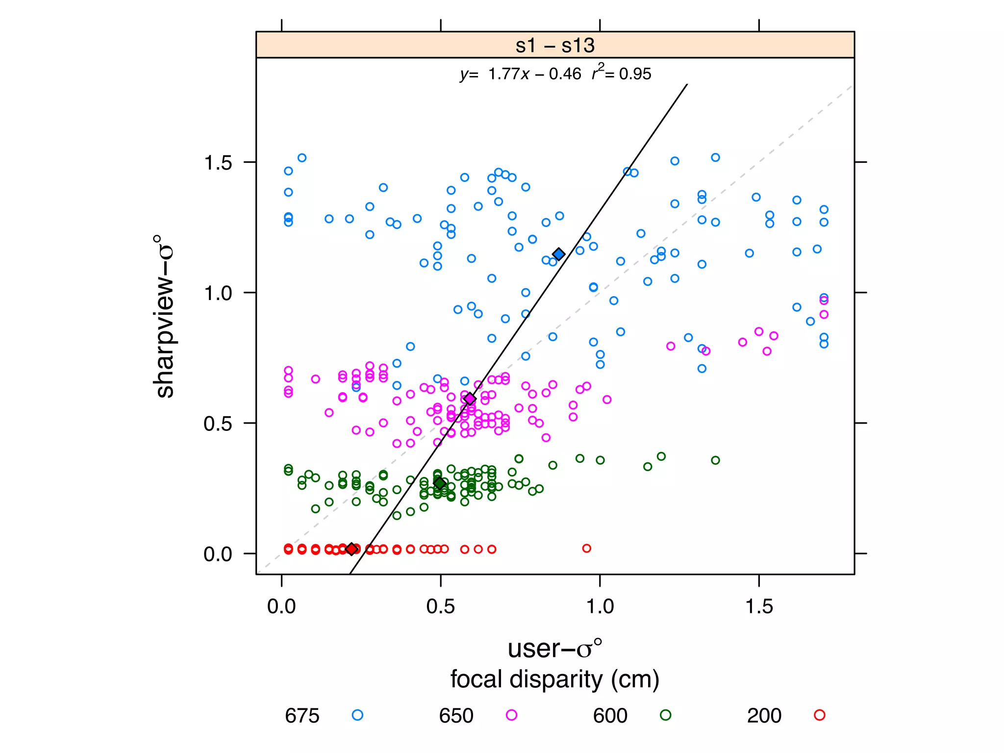
![onvergence of the eyes, and the distance of the
ated close to the horopter (see Section 4.4.1) can
ge around the horopter at which this is possible
rea. However, in addition to absolute disparity,
y-based depth perception. For example, the gra-
., the depth gradient) influence depth perception
depth perception content dependent. Further-
isparity is processed and depth is perceived can
conflicting cues (e.g., inconsistent convergence
ection 4.4.2) and nonconflicting cues, and an up-
modulation frequency of disparity exists. A good
ed depth perception can be found in [103].
onvergence and retinal disparity are the main
, there are others.
commodation and visual depth of field.
LIGHT FIELD DISPLAYS
WWW.DISPLAYSBOOK.INFO
VISION:
DISPLAY AS WINDOW
408 9. Three-Dimensional Disp
Figure 9.35. Light-field recording and reconstruction principle: light rays just pas
a window (left), light rays converted into pixel values on a tiny image senso
a pinhole camera (center), light rays reproduced by a tiny projector being jus
inverted pinhole camera (right).
a distance. In principle, this turns out to be quite simple. Any cam
with a su ciently small aperture will just record angles and intens
of incident light rays and map them onto the pixels of its image sen
(Figure 9.35). Hence small cameras of, for example, 1 mm in size an
su cient number of (in this case very tiny) pixels can deliver the light-fi
data for just one window segment, which we will call a pixel of the wind
Any camera can in general be seen as an angle-to-position converter. T
conversion is relatively robust with respect to geometric errors.
Reproducing the light field on a display is straightforward (at leas
theory): we could use identical optical assemblies, this time illumina
SENSOR
ARRAY
DISPLAY
ARRAY
120 4. Basics of Visual Perception
• Focus e↵ects (blurring of objects not in the lens focus)
• Haze (softened image parts appear more distant)
• Color (bluish objects appear more distant)
• Motion parallax (images change when the head moves)
• Motion dynamics (objects change sizes and positions, in motion)
Convergence. As explained already, convergence is the inward rotation of
the eyes when targeting a distant object (Figure 4.24). The state of the
eye muscles gives us a hint about depth for up to 10 meters. However, we
don’t get extremely fine angular resolutions at this distance.
Figure 4.24. Convergence (up to 10 m).
Retinal disparity. For longer distances, the di↵erence between the two im-
ages projected onto the retinas (called retinal disparity) is far more e cient
than convergence. Near objects block distant ones at slightly di↵erent po-
sitions, resulting in di↵erent images generated by the left and right eyes
(Figure 4.25).
VERGENCEACCOMMODATION
GOAL: NATURAL HUMAN VISUAL PERCEPTION](https://image.slidesharecdn.com/16idw-161207022929/75/Keynote-at-23rd-International-Display-Workshop-15-2048.jpg)


![depth perception content dependent. Further-
isparity is processed and depth is perceived can
conflicting cues (e.g., inconsistent convergence
ection 4.4.2) and nonconflicting cues, and an up-
modulation frequency of disparity exists. A good
ed depth perception can be found in [103].
onvergence and retinal disparity are the main
, there are others.
commodation and visual depth of field.
PERSONALIZED AR:
A SMARTER APPROACH
• Focus e↵ects (blurring of objects not in the lens focus)
• Haze (softened image parts appear more distant)
• Color (bluish objects appear more distant)
• Motion parallax (images change when the head moves)
• Motion dynamics (objects change sizes and positions, in motion)
Convergence. As explained already, convergence is the inward rotation of
the eyes when targeting a distant object (Figure 4.24). The state of the
eye muscles gives us a hint about depth for up to 10 meters. However, we
don’t get extremely fine angular resolutions at this distance.
Figure 4.24. Convergence (up to 10 m).
Retinal disparity. For longer distances, the di↵erence between the two im-
ages projected onto the retinas (called retinal disparity) is far more e cient
than convergence. Near objects block distant ones at slightly di↵erent po-
sitions, resulting in di↵erent images generated by the left and right eyes
(Figure 4.25).
The di↵erences at object edges can be perceived up to the crispness
limit of our vision. With a typical eye-to-eye distance (also called interoc-
ular distance) of about six centimeters and an angular resolution of one
KEY IDEA: MEASURE HUMAN VISUAL SYSTEM & DISPLAY SUBSET OF
LIGHT FIELD
BENEFIT: REDUCE REQUIRED DISPLAY PIXELS BY SEVERAL ORDERS
OF MAGNITUDE
WILL BE ACHIEVED WELL BEFORE SURROUND AR!
VERGENCEACCOMMODATION](https://image.slidesharecdn.com/16idw-161207022929/75/Keynote-at-23rd-International-Display-Workshop-18-2048.jpg)
![PHILOSOPHY: TRUE AUGMENTED REALITY
There have been a number of shape displays based on pin
architecture. The FEELEX project [14] was one of the early
attempts to design combined shapes and computer graphics
displays that can be explored by touch. FEELEX consisted
of several mechanical pistons actuated by motors and cov-
ered by a soft silicon surface. The images were projected
onto its surface and synchronized with the movement of the
pistons, creating simple shapes.
Lumen [32] is a low resolution, 13 by 13-pixel, bit-map
display where each pixel can also physically move up and
down (Figure 4). The resulting display can present both 2D
graphic images and moving physical shapes that can be
observed, touched, and felt with the hands. The 2D position
Figure 2.7: Hand-fixed reference frame: Augmentations move
example shows a user discussing a virtual map wit
map from di↵erent angles, he can pick it up from t
his belt and put it in his hand.
DISPLAYS
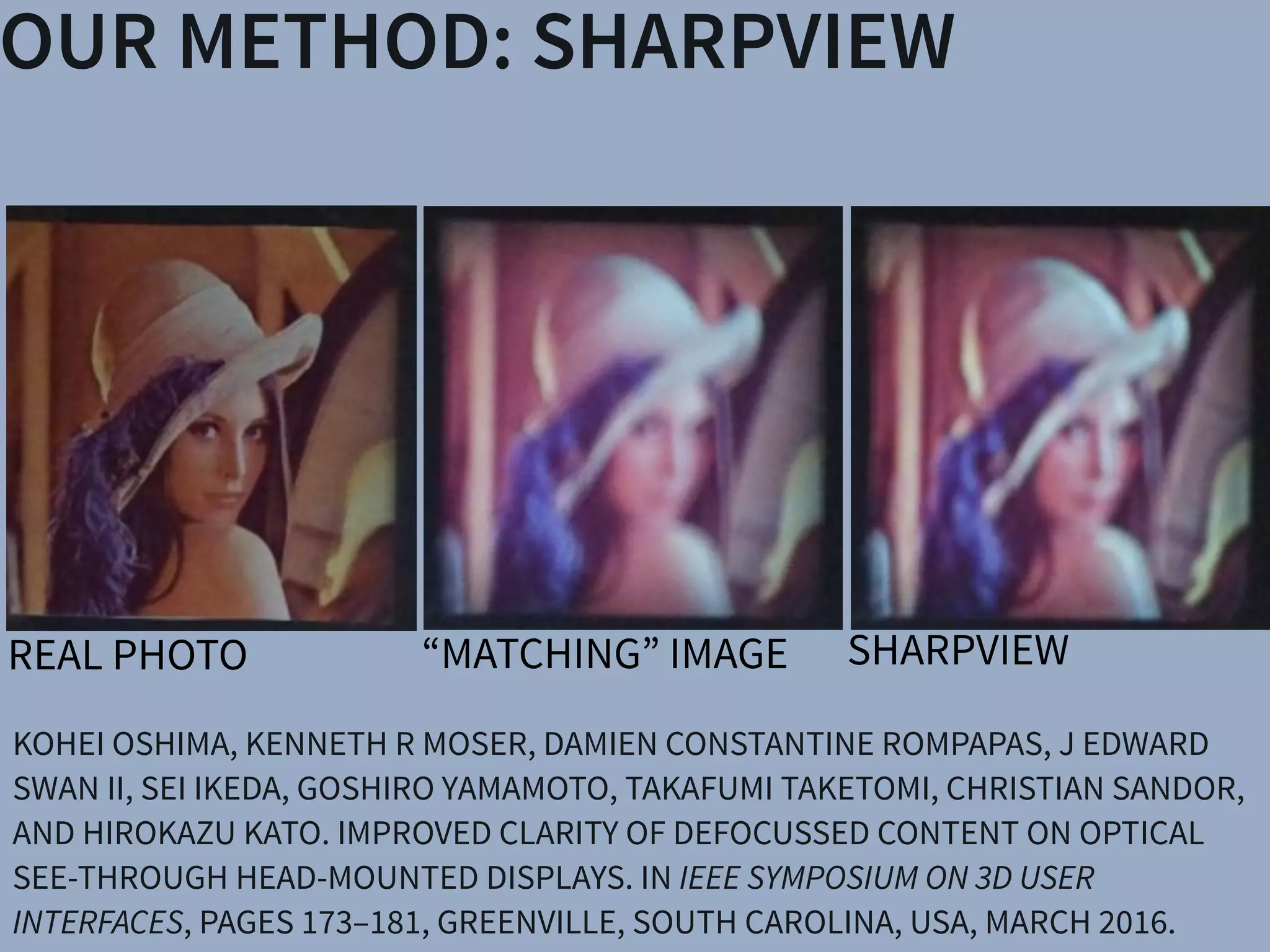
SharpView: Improved Clarity of Defocused C
See-Through Head-Mounted Dis
Kohei Oshima⇤ † Kenneth R Moser⇤ ‡ Damien Constantine Rompapas†
Goshiro Yamamoto† Takafumi Taketomi† Christian San
†Interactive Media Design Laboratory
Nara Institute of Science and Technology
‡Computer Science & Engineering
Mississippi State University
(a) (b) (c)
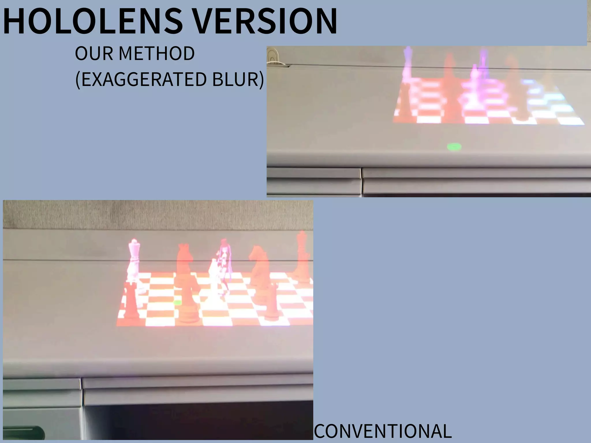
Figure 1: The cause and effect of focus blur in Optical See-Through (OST) Head-Mounted Displa
HMD and related hardware used in our study. (b) Simplified schematic of an OST AR system. B
and real world imagery are viewed at unequal focal distances. (c), (d), (e): Views through an O
world image (c) is in focus, causing the virtual image (d) to appear blurred; (e) an improved virtua
SharpView: Improved Clarity of Defocused Content on Optical
See-Through Head-Mounted Displays
Kohei Oshima⇤ † Kenneth R Moser⇤ ‡ Damien Constantine Rompapas† J. Edward Swan II‡ Sei Ikeda§
Goshiro Yamamoto† Takafumi Taketomi† Christian Sandor† Hirokazu Kato†
†Interactive Media Design Laboratory
Nara Institute of Science and Technology
‡Computer Science & Engineering
Mississippi State University
§Mobile Computing Laboratory
Ritsumeikan University
(a) (b) (c) (d) (e)
Figure 1: The cause and effect of focus blur in Optical See-Through (OST) Head-Mounted Display (HMD) systems. (a) A user wearing the OST
HMD and related hardware used in our study. (b) Simplified schematic of an OST AR system. Blurring occurs when the virtual display screen
and real world imagery are viewed at unequal focal distances. (c), (d), (e): Views through an OST Augmented Reality system, where the real
world image (c) is in focus, causing the virtual image (d) to appear blurred; (e) an improved virtual image after application of SharpView.
ABSTRACT
Augmented Reality (AR) systems, which utilize optical see-through
head-mounted displays, are becoming more common place, with
several consumer level options already available, and the promise of
additional, more advanced, devices on the horizon. A common fac-
tor among current generation optical see-through devices, though,
is fixed focal distance to virtual content. While fixed focus is not a
concern for video see-through AR, since both virtual and real world
imagery are combined into a single image by the display, unequal
distances between real world objects and the virtual display screen
in optical see-through AR is unavoidable.
In this work, we investigate the issue of focus blur, in particular,
the blurring caused by simultaneously viewing virtual content and
physical objects in the environment at differing focal distances. We
Multimedia Information Systems—Artificial, augmented, and vir-
tual realities; I.4.4 [Image Processing and Computer Vision]:
Restoration—Wiener filtering
1 INTRODUCTION
Optical See-Through (OST) Head-Mounted Displays (HMDs) have
seen an increase in both popularity and accessibility with the re-
lease of several consumer level options, including Google Glass
and Epson Moverio BT-200, and announced future offerings, such
as Microsoft’s HoloLens, on the horizon. The transparent display
technology used in these HMDs affords a unique experience, allow-
ing the user to view on-screen computer generated (CG) content
while maintaining a direct view of their environment, a property
extremely well suited for augmented reality (AR) systems. Un-
arpView: Improved Clarity of Defocused Content on Optical
See-Through Head-Mounted Displays
ma⇤ † Kenneth R Moser⇤ ‡ Damien Constantine Rompapas† J. Edward Swan II‡ Sei Ikeda§
Goshiro Yamamoto† Takafumi Taketomi† Christian Sandor† Hirokazu Kato†
active Media Design Laboratory
stitute of Science and Technology
‡Computer Science & Engineering
Mississippi State University
§Mobile Computing Laboratory
Ritsumeikan University
(b) (c) (d) (e)
use and effect of focus blur in Optical See-Through (OST) Head-Mounted Display (HMD) systems. (a) A user wearing the OST
hardware used in our study. (b) Simplified schematic of an OST AR system. Blurring occurs when the virtual display screen
magery are viewed at unequal focal distances. (c), (d), (e): Views through an OST Augmented Reality system, where the real
s in focus, causing the virtual image (d) to appear blurred; (e) an improved virtual image after application of SharpView.
ity (AR) systems, which utilize optical see-through
isplays, are becoming more common place, with
r level options already available, and the promise of
advanced, devices on the horizon. A common fac-
nt generation optical see-through devices, though,
Multimedia Information Systems—Artificial, augmented, and vir-
tual realities; I.4.4 [Image Processing and Computer Vision]:
Restoration—Wiener filtering
1 INTRODUCTION
Optical See-Through (OST) Head-Mounted Displays (HMDs) have
n of a Semi-Automatic Optical See-Through
nted Display Calibration Technique
E, Yuta Itoh, Student Member, IEEE, Kohei Oshima, Student Member, IEEE,
E, Gudrun Klinker, Member, IEEE, and Christian Sandor, Member, IEEE
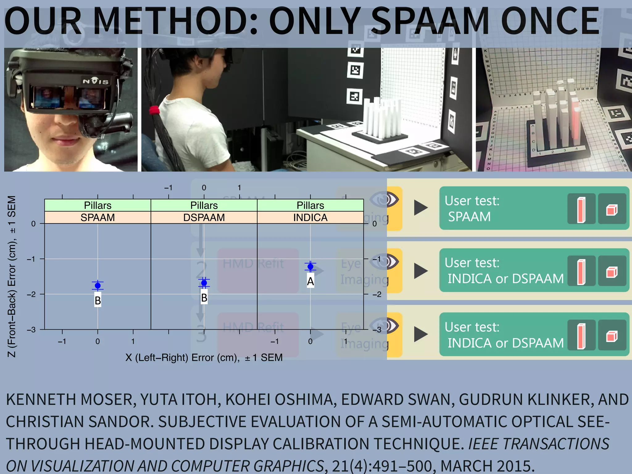
. (a) Display and camera system. (b) Task layout. (c) Pillars task. (d) Cubes task.
of optical see-through (OST) head-mounted displays (HMDs), there is a present need for
bration methods suited for non-expert users. This work presents the results of a user study
mines registration accuracy produced by three OST HMD calibration methods: (1) SPAAM,
NDICA, a recently developed semi-automatic calibration method. Accuracy metrics used
ality values and error between perceived and absolute registration coordinates. Our results
e very accurate registration in the horizontal direction but caused subjects to perceive the
EEE TRANSACTIONS ON VISUALIZATION AND COMPUTER GRAPHICS, VOL. 21, NO. ,4 APRIL2015
GEOMETRIC
ALIGNMENT
REMOVE
BLUR
ARTIFACTS
CREATE
CORRECT
BLUR](https://image.slidesharecdn.com/16idw-161207022929/75/Keynote-at-23rd-International-Display-Workshop-19-2048.jpg)


![DISPLAYSSharpView: Improved Clarity of Defocused C
See-Through Head-Mounted Dis
Kohei Oshima⇤ † Kenneth R Moser⇤ ‡ Damien Constantine Rompapas†
Goshiro Yamamoto† Takafumi Taketomi† Christian San
†Interactive Media Design Laboratory
Nara Institute of Science and Technology
‡Computer Science & Engineering
Mississippi State University
(a) (b) (c)
Figure 1: The cause and effect of focus blur in Optical See-Through (OST) Head-Mounted Displa
HMD and related hardware used in our study. (b) Simplified schematic of an OST AR system. B
and real world imagery are viewed at unequal focal distances. (c), (d), (e): Views through an O
world image (c) is in focus, causing the virtual image (d) to appear blurred; (e) an improved virtua
SharpView: Improved Clarity of Defocused Content on Optical
See-Through Head-Mounted Displays
Kohei Oshima⇤ † Kenneth R Moser⇤ ‡ Damien Constantine Rompapas† J. Edward Swan II‡ Sei Ikeda§
Goshiro Yamamoto† Takafumi Taketomi† Christian Sandor† Hirokazu Kato†
†Interactive Media Design Laboratory
Nara Institute of Science and Technology
‡Computer Science & Engineering
Mississippi State University
§Mobile Computing Laboratory
Ritsumeikan University
(a) (b) (c) (d) (e)
Figure 1: The cause and effect of focus blur in Optical See-Through (OST) Head-Mounted Display (HMD) systems. (a) A user wearing the OST
HMD and related hardware used in our study. (b) Simplified schematic of an OST AR system. Blurring occurs when the virtual display screen
and real world imagery are viewed at unequal focal distances. (c), (d), (e): Views through an OST Augmented Reality system, where the real
world image (c) is in focus, causing the virtual image (d) to appear blurred; (e) an improved virtual image after application of SharpView.
ABSTRACT
Augmented Reality (AR) systems, which utilize optical see-through
head-mounted displays, are becoming more common place, with
several consumer level options already available, and the promise of
additional, more advanced, devices on the horizon. A common fac-
tor among current generation optical see-through devices, though,
is fixed focal distance to virtual content. While fixed focus is not a
concern for video see-through AR, since both virtual and real world
imagery are combined into a single image by the display, unequal
distances between real world objects and the virtual display screen
in optical see-through AR is unavoidable.
In this work, we investigate the issue of focus blur, in particular,
the blurring caused by simultaneously viewing virtual content and
physical objects in the environment at differing focal distances. We
Multimedia Information Systems—Artificial, augmented, and vir-
tual realities; I.4.4 [Image Processing and Computer Vision]:
Restoration—Wiener filtering
1 INTRODUCTION
Optical See-Through (OST) Head-Mounted Displays (HMDs) have
seen an increase in both popularity and accessibility with the re-
lease of several consumer level options, including Google Glass
and Epson Moverio BT-200, and announced future offerings, such
as Microsoft’s HoloLens, on the horizon. The transparent display
technology used in these HMDs affords a unique experience, allow-
ing the user to view on-screen computer generated (CG) content
while maintaining a direct view of their environment, a property
extremely well suited for augmented reality (AR) systems. Un-
arpView: Improved Clarity of Defocused Content on Optical
See-Through Head-Mounted Displays
ma⇤ † Kenneth R Moser⇤ ‡ Damien Constantine Rompapas† J. Edward Swan II‡ Sei Ikeda§
Goshiro Yamamoto† Takafumi Taketomi† Christian Sandor† Hirokazu Kato†
active Media Design Laboratory
stitute of Science and Technology
‡Computer Science & Engineering
Mississippi State University
§Mobile Computing Laboratory
Ritsumeikan University
(b) (c) (d) (e)
use and effect of focus blur in Optical See-Through (OST) Head-Mounted Display (HMD) systems. (a) A user wearing the OST
hardware used in our study. (b) Simplified schematic of an OST AR system. Blurring occurs when the virtual display screen
magery are viewed at unequal focal distances. (c), (d), (e): Views through an OST Augmented Reality system, where the real
s in focus, causing the virtual image (d) to appear blurred; (e) an improved virtual image after application of SharpView.
ity (AR) systems, which utilize optical see-through
isplays, are becoming more common place, with
r level options already available, and the promise of
advanced, devices on the horizon. A common fac-
nt generation optical see-through devices, though,
Multimedia Information Systems—Artificial, augmented, and vir-
tual realities; I.4.4 [Image Processing and Computer Vision]:
Restoration—Wiener filtering
1 INTRODUCTION
Optical See-Through (OST) Head-Mounted Displays (HMDs) have
n of a Semi-Automatic Optical See-Through
nted Display Calibration Technique
E, Yuta Itoh, Student Member, IEEE, Kohei Oshima, Student Member, IEEE,
E, Gudrun Klinker, Member, IEEE, and Christian Sandor, Member, IEEE
. (a) Display and camera system. (b) Task layout. (c) Pillars task. (d) Cubes task.
of optical see-through (OST) head-mounted displays (HMDs), there is a present need for
bration methods suited for non-expert users. This work presents the results of a user study
mines registration accuracy produced by three OST HMD calibration methods: (1) SPAAM,
NDICA, a recently developed semi-automatic calibration method. Accuracy metrics used
ality values and error between perceived and absolute registration coordinates. Our results
e very accurate registration in the horizontal direction but caused subjects to perceive the
EEE TRANSACTIONS ON VISUALIZATION AND COMPUTER GRAPHICS, VOL. 21, NO. ,4 APRIL2015
PHILOSOPHY: TRUE AUGMENTED REALITY
There have been a number of shape displays based on pin
architecture. The FEELEX project [14] was one of the early
attempts to design combined shapes and computer graphics
displays that can be explored by touch. FEELEX consisted
of several mechanical pistons actuated by motors and cov-
ered by a soft silicon surface. The images were projected
onto its surface and synchronized with the movement of the
pistons, creating simple shapes.
Lumen [32] is a low resolution, 13 by 13-pixel, bit-map
display where each pixel can also physically move up and
down (Figure 4). The resulting display can present both 2D
graphic images and moving physical shapes that can be
observed, touched, and felt with the hands. The 2D position
Figure 2.7: Hand-fixed reference frame: Augmentations move
example shows a user discussing a virtual map wit
map from di↵erent angles, he can pick it up from t
his belt and put it in his hand.](https://image.slidesharecdn.com/16idw-161207022929/75/Keynote-at-23rd-International-Display-Workshop-36-2048.jpg)


![DISPLAYS APPLICATIONSSharpView: Improved Clarity of Defocused C
See-Through Head-Mounted Dis
Kohei Oshima⇤ † Kenneth R Moser⇤ ‡ Damien Constantine Rompapas†
Goshiro Yamamoto† Takafumi Taketomi† Christian San
†Interactive Media Design Laboratory
Nara Institute of Science and Technology
‡Computer Science & Engineering
Mississippi State University
(a) (b) (c)
Figure 1: The cause and effect of focus blur in Optical See-Through (OST) Head-Mounted Displa
HMD and related hardware used in our study. (b) Simplified schematic of an OST AR system. B
and real world imagery are viewed at unequal focal distances. (c), (d), (e): Views through an O
world image (c) is in focus, causing the virtual image (d) to appear blurred; (e) an improved virtua
SharpView: Improved Clarity of Defocused Content on Optical
See-Through Head-Mounted Displays
Kohei Oshima⇤ † Kenneth R Moser⇤ ‡ Damien Constantine Rompapas† J. Edward Swan II‡ Sei Ikeda§
Goshiro Yamamoto† Takafumi Taketomi† Christian Sandor† Hirokazu Kato†
†Interactive Media Design Laboratory
Nara Institute of Science and Technology
‡Computer Science & Engineering
Mississippi State University
§Mobile Computing Laboratory
Ritsumeikan University
(a) (b) (c) (d) (e)
Figure 1: The cause and effect of focus blur in Optical See-Through (OST) Head-Mounted Display (HMD) systems. (a) A user wearing the OST
HMD and related hardware used in our study. (b) Simplified schematic of an OST AR system. Blurring occurs when the virtual display screen
and real world imagery are viewed at unequal focal distances. (c), (d), (e): Views through an OST Augmented Reality system, where the real
world image (c) is in focus, causing the virtual image (d) to appear blurred; (e) an improved virtual image after application of SharpView.
ABSTRACT
Augmented Reality (AR) systems, which utilize optical see-through
head-mounted displays, are becoming more common place, with
several consumer level options already available, and the promise of
additional, more advanced, devices on the horizon. A common fac-
tor among current generation optical see-through devices, though,
is fixed focal distance to virtual content. While fixed focus is not a
concern for video see-through AR, since both virtual and real world
imagery are combined into a single image by the display, unequal
distances between real world objects and the virtual display screen
in optical see-through AR is unavoidable.
In this work, we investigate the issue of focus blur, in particular,
the blurring caused by simultaneously viewing virtual content and
physical objects in the environment at differing focal distances. We
Multimedia Information Systems—Artificial, augmented, and vir-
tual realities; I.4.4 [Image Processing and Computer Vision]:
Restoration—Wiener filtering
1 INTRODUCTION
Optical See-Through (OST) Head-Mounted Displays (HMDs) have
seen an increase in both popularity and accessibility with the re-
lease of several consumer level options, including Google Glass
and Epson Moverio BT-200, and announced future offerings, such
as Microsoft’s HoloLens, on the horizon. The transparent display
technology used in these HMDs affords a unique experience, allow-
ing the user to view on-screen computer generated (CG) content
while maintaining a direct view of their environment, a property
extremely well suited for augmented reality (AR) systems. Un-
arpView: Improved Clarity of Defocused Content on Optical
See-Through Head-Mounted Displays
ma⇤ † Kenneth R Moser⇤ ‡ Damien Constantine Rompapas† J. Edward Swan II‡ Sei Ikeda§
Goshiro Yamamoto† Takafumi Taketomi† Christian Sandor† Hirokazu Kato†
active Media Design Laboratory
stitute of Science and Technology
‡Computer Science & Engineering
Mississippi State University
§Mobile Computing Laboratory
Ritsumeikan University
(b) (c) (d) (e)
use and effect of focus blur in Optical See-Through (OST) Head-Mounted Display (HMD) systems. (a) A user wearing the OST
hardware used in our study. (b) Simplified schematic of an OST AR system. Blurring occurs when the virtual display screen
magery are viewed at unequal focal distances. (c), (d), (e): Views through an OST Augmented Reality system, where the real
s in focus, causing the virtual image (d) to appear blurred; (e) an improved virtual image after application of SharpView.
ity (AR) systems, which utilize optical see-through
isplays, are becoming more common place, with
r level options already available, and the promise of
advanced, devices on the horizon. A common fac-
nt generation optical see-through devices, though,
Multimedia Information Systems—Artificial, augmented, and vir-
tual realities; I.4.4 [Image Processing and Computer Vision]:
Restoration—Wiener filtering
1 INTRODUCTION
Optical See-Through (OST) Head-Mounted Displays (HMDs) have
n of a Semi-Automatic Optical See-Through
nted Display Calibration Technique
E, Yuta Itoh, Student Member, IEEE, Kohei Oshima, Student Member, IEEE,
E, Gudrun Klinker, Member, IEEE, and Christian Sandor, Member, IEEE
. (a) Display and camera system. (b) Task layout. (c) Pillars task. (d) Cubes task.
of optical see-through (OST) head-mounted displays (HMDs), there is a present need for
bration methods suited for non-expert users. This work presents the results of a user study
mines registration accuracy produced by three OST HMD calibration methods: (1) SPAAM,
NDICA, a recently developed semi-automatic calibration method. Accuracy metrics used
ality values and error between perceived and absolute registration coordinates. Our results
e very accurate registration in the horizontal direction but caused subjects to perceive the
EEE TRANSACTIONS ON VISUALIZATION AND COMPUTER GRAPHICS, VOL. 21, NO. ,4 APRIL2015
PHILOSOPHY: TRUE AUGMENTED REALITY
There have been a number of shape displays based on pin
architecture. The FEELEX project [14] was one of the early
attempts to design combined shapes and computer graphics
displays that can be explored by touch. FEELEX consisted
of several mechanical pistons actuated by motors and cov-
ered by a soft silicon surface. The images were projected
onto its surface and synchronized with the movement of the
pistons, creating simple shapes.
Lumen [32] is a low resolution, 13 by 13-pixel, bit-map
display where each pixel can also physically move up and
down (Figure 4). The resulting display can present both 2D
graphic images and moving physical shapes that can be
observed, touched, and felt with the hands. The 2D position
Figure 2.7: Hand-fixed reference frame: Augmentations move
example shows a user discussing a virtual map wit
map from di↵erent angles, he can pick it up from t
his belt and put it in his hand.](https://image.slidesharecdn.com/16idw-161207022929/75/Keynote-at-23rd-International-Display-Workshop-45-2048.jpg)


![DISPLAYS APPLICATIONSSharpView: Improved Clarity of Defocused C
See-Through Head-Mounted Dis
Kohei Oshima⇤ † Kenneth R Moser⇤ ‡ Damien Constantine Rompapas†
Goshiro Yamamoto† Takafumi Taketomi† Christian San
†Interactive Media Design Laboratory
Nara Institute of Science and Technology
‡Computer Science & Engineering
Mississippi State University
(a) (b) (c)
Figure 1: The cause and effect of focus blur in Optical See-Through (OST) Head-Mounted Displa
HMD and related hardware used in our study. (b) Simplified schematic of an OST AR system. B
and real world imagery are viewed at unequal focal distances. (c), (d), (e): Views through an O
world image (c) is in focus, causing the virtual image (d) to appear blurred; (e) an improved virtua
SharpView: Improved Clarity of Defocused Content on Optical
See-Through Head-Mounted Displays
Kohei Oshima⇤ † Kenneth R Moser⇤ ‡ Damien Constantine Rompapas† J. Edward Swan II‡ Sei Ikeda§
Goshiro Yamamoto† Takafumi Taketomi† Christian Sandor† Hirokazu Kato†
†Interactive Media Design Laboratory
Nara Institute of Science and Technology
‡Computer Science & Engineering
Mississippi State University
§Mobile Computing Laboratory
Ritsumeikan University
(a) (b) (c) (d) (e)
Figure 1: The cause and effect of focus blur in Optical See-Through (OST) Head-Mounted Display (HMD) systems. (a) A user wearing the OST
HMD and related hardware used in our study. (b) Simplified schematic of an OST AR system. Blurring occurs when the virtual display screen
and real world imagery are viewed at unequal focal distances. (c), (d), (e): Views through an OST Augmented Reality system, where the real
world image (c) is in focus, causing the virtual image (d) to appear blurred; (e) an improved virtual image after application of SharpView.
ABSTRACT
Augmented Reality (AR) systems, which utilize optical see-through
head-mounted displays, are becoming more common place, with
several consumer level options already available, and the promise of
additional, more advanced, devices on the horizon. A common fac-
tor among current generation optical see-through devices, though,
is fixed focal distance to virtual content. While fixed focus is not a
concern for video see-through AR, since both virtual and real world
imagery are combined into a single image by the display, unequal
distances between real world objects and the virtual display screen
in optical see-through AR is unavoidable.
In this work, we investigate the issue of focus blur, in particular,
the blurring caused by simultaneously viewing virtual content and
physical objects in the environment at differing focal distances. We
Multimedia Information Systems—Artificial, augmented, and vir-
tual realities; I.4.4 [Image Processing and Computer Vision]:
Restoration—Wiener filtering
1 INTRODUCTION
Optical See-Through (OST) Head-Mounted Displays (HMDs) have
seen an increase in both popularity and accessibility with the re-
lease of several consumer level options, including Google Glass
and Epson Moverio BT-200, and announced future offerings, such
as Microsoft’s HoloLens, on the horizon. The transparent display
technology used in these HMDs affords a unique experience, allow-
ing the user to view on-screen computer generated (CG) content
while maintaining a direct view of their environment, a property
extremely well suited for augmented reality (AR) systems. Un-
arpView: Improved Clarity of Defocused Content on Optical
See-Through Head-Mounted Displays
ma⇤ † Kenneth R Moser⇤ ‡ Damien Constantine Rompapas† J. Edward Swan II‡ Sei Ikeda§
Goshiro Yamamoto† Takafumi Taketomi† Christian Sandor† Hirokazu Kato†
active Media Design Laboratory
stitute of Science and Technology
‡Computer Science & Engineering
Mississippi State University
§Mobile Computing Laboratory
Ritsumeikan University
(b) (c) (d) (e)
use and effect of focus blur in Optical See-Through (OST) Head-Mounted Display (HMD) systems. (a) A user wearing the OST
hardware used in our study. (b) Simplified schematic of an OST AR system. Blurring occurs when the virtual display screen
magery are viewed at unequal focal distances. (c), (d), (e): Views through an OST Augmented Reality system, where the real
s in focus, causing the virtual image (d) to appear blurred; (e) an improved virtual image after application of SharpView.
ity (AR) systems, which utilize optical see-through
isplays, are becoming more common place, with
r level options already available, and the promise of
advanced, devices on the horizon. A common fac-
nt generation optical see-through devices, though,
Multimedia Information Systems—Artificial, augmented, and vir-
tual realities; I.4.4 [Image Processing and Computer Vision]:
Restoration—Wiener filtering
1 INTRODUCTION
Optical See-Through (OST) Head-Mounted Displays (HMDs) have
n of a Semi-Automatic Optical See-Through
nted Display Calibration Technique
E, Yuta Itoh, Student Member, IEEE, Kohei Oshima, Student Member, IEEE,
E, Gudrun Klinker, Member, IEEE, and Christian Sandor, Member, IEEE
. (a) Display and camera system. (b) Task layout. (c) Pillars task. (d) Cubes task.
of optical see-through (OST) head-mounted displays (HMDs), there is a present need for
bration methods suited for non-expert users. This work presents the results of a user study
mines registration accuracy produced by three OST HMD calibration methods: (1) SPAAM,
NDICA, a recently developed semi-automatic calibration method. Accuracy metrics used
ality values and error between perceived and absolute registration coordinates. Our results
e very accurate registration in the horizontal direction but caused subjects to perceive the
EEE TRANSACTIONS ON VISUALIZATION AND COMPUTER GRAPHICS, VOL. 21, NO. ,4 APRIL2015
PHILOSOPHY: TRUE AUGMENTED REALITY
There have been a number of shape displays based on pin
architecture. The FEELEX project [14] was one of the early
attempts to design combined shapes and computer graphics
displays that can be explored by touch. FEELEX consisted
of several mechanical pistons actuated by motors and cov-
ered by a soft silicon surface. The images were projected
onto its surface and synchronized with the movement of the
pistons, creating simple shapes.
Lumen [32] is a low resolution, 13 by 13-pixel, bit-map
display where each pixel can also physically move up and
down (Figure 4). The resulting display can present both 2D
graphic images and moving physical shapes that can be
observed, touched, and felt with the hands. The 2D position
Figure 2.7: Hand-fixed reference frame: Augmentations move
example shows a user discussing a virtual map wit
map from di↵erent angles, he can pick it up from t
his belt and put it in his hand.](https://image.slidesharecdn.com/16idw-161207022929/75/Keynote-at-23rd-International-Display-Workshop-57-2048.jpg)


![PHILOSOPHY: TRUE AUGMENTED REALITY
There have been a number of shape displays based on pin
architecture. The FEELEX project [14] was one of the early
attempts to design combined shapes and computer graphics
displays that can be explored by touch. FEELEX consisted
of several mechanical pistons actuated by motors and cov-
ered by a soft silicon surface. The images were projected
onto its surface and synchronized with the movement of the
pistons, creating simple shapes.
Lumen [32] is a low resolution, 13 by 13-pixel, bit-map
display where each pixel can also physically move up and
down (Figure 4). The resulting display can present both 2D
graphic images and moving physical shapes that can be
observed, touched, and felt with the hands. The 2D position
Figure 2.7: Hand-fixed reference frame: Augmentations move
example shows a user discussing a virtual map wit
map from di↵erent angles, he can pick it up from t
his belt and put it in his hand.
DISPLAYS APPLICATIONSSharpView: Improved Clarity of Defocused C
See-Through Head-Mounted Dis
Kohei Oshima⇤ † Kenneth R Moser⇤ ‡ Damien Constantine Rompapas†
Goshiro Yamamoto† Takafumi Taketomi† Christian San
†Interactive Media Design Laboratory
Nara Institute of Science and Technology
‡Computer Science & Engineering
Mississippi State University
(a) (b) (c)
Figure 1: The cause and effect of focus blur in Optical See-Through (OST) Head-Mounted Displa
HMD and related hardware used in our study. (b) Simplified schematic of an OST AR system. B
and real world imagery are viewed at unequal focal distances. (c), (d), (e): Views through an O
world image (c) is in focus, causing the virtual image (d) to appear blurred; (e) an improved virtua
SharpView: Improved Clarity of Defocused Content on Optical
See-Through Head-Mounted Displays
Kohei Oshima⇤ † Kenneth R Moser⇤ ‡ Damien Constantine Rompapas† J. Edward Swan II‡ Sei Ikeda§
Goshiro Yamamoto† Takafumi Taketomi† Christian Sandor† Hirokazu Kato†
†Interactive Media Design Laboratory
Nara Institute of Science and Technology
‡Computer Science & Engineering
Mississippi State University
§Mobile Computing Laboratory
Ritsumeikan University
(a) (b) (c) (d) (e)
Figure 1: The cause and effect of focus blur in Optical See-Through (OST) Head-Mounted Display (HMD) systems. (a) A user wearing the OST
HMD and related hardware used in our study. (b) Simplified schematic of an OST AR system. Blurring occurs when the virtual display screen
and real world imagery are viewed at unequal focal distances. (c), (d), (e): Views through an OST Augmented Reality system, where the real
world image (c) is in focus, causing the virtual image (d) to appear blurred; (e) an improved virtual image after application of SharpView.
ABSTRACT
Augmented Reality (AR) systems, which utilize optical see-through
head-mounted displays, are becoming more common place, with
several consumer level options already available, and the promise of
additional, more advanced, devices on the horizon. A common fac-
tor among current generation optical see-through devices, though,
is fixed focal distance to virtual content. While fixed focus is not a
concern for video see-through AR, since both virtual and real world
imagery are combined into a single image by the display, unequal
distances between real world objects and the virtual display screen
in optical see-through AR is unavoidable.
In this work, we investigate the issue of focus blur, in particular,
the blurring caused by simultaneously viewing virtual content and
physical objects in the environment at differing focal distances. We
Multimedia Information Systems—Artificial, augmented, and vir-
tual realities; I.4.4 [Image Processing and Computer Vision]:
Restoration—Wiener filtering
1 INTRODUCTION
Optical See-Through (OST) Head-Mounted Displays (HMDs) have
seen an increase in both popularity and accessibility with the re-
lease of several consumer level options, including Google Glass
and Epson Moverio BT-200, and announced future offerings, such
as Microsoft’s HoloLens, on the horizon. The transparent display
technology used in these HMDs affords a unique experience, allow-
ing the user to view on-screen computer generated (CG) content
while maintaining a direct view of their environment, a property
extremely well suited for augmented reality (AR) systems. Un-
arpView: Improved Clarity of Defocused Content on Optical
See-Through Head-Mounted Displays
ma⇤ † Kenneth R Moser⇤ ‡ Damien Constantine Rompapas† J. Edward Swan II‡ Sei Ikeda§
Goshiro Yamamoto† Takafumi Taketomi† Christian Sandor† Hirokazu Kato†
active Media Design Laboratory
stitute of Science and Technology
‡Computer Science & Engineering
Mississippi State University
§Mobile Computing Laboratory
Ritsumeikan University
(b) (c) (d) (e)
use and effect of focus blur in Optical See-Through (OST) Head-Mounted Display (HMD) systems. (a) A user wearing the OST
hardware used in our study. (b) Simplified schematic of an OST AR system. Blurring occurs when the virtual display screen
magery are viewed at unequal focal distances. (c), (d), (e): Views through an OST Augmented Reality system, where the real
s in focus, causing the virtual image (d) to appear blurred; (e) an improved virtual image after application of SharpView.
ity (AR) systems, which utilize optical see-through
isplays, are becoming more common place, with
r level options already available, and the promise of
advanced, devices on the horizon. A common fac-
nt generation optical see-through devices, though,
Multimedia Information Systems—Artificial, augmented, and vir-
tual realities; I.4.4 [Image Processing and Computer Vision]:
Restoration—Wiener filtering
1 INTRODUCTION
Optical See-Through (OST) Head-Mounted Displays (HMDs) have
n of a Semi-Automatic Optical See-Through
nted Display Calibration Technique
E, Yuta Itoh, Student Member, IEEE, Kohei Oshima, Student Member, IEEE,
E, Gudrun Klinker, Member, IEEE, and Christian Sandor, Member, IEEE
. (a) Display and camera system. (b) Task layout. (c) Pillars task. (d) Cubes task.
of optical see-through (OST) head-mounted displays (HMDs), there is a present need for
bration methods suited for non-expert users. This work presents the results of a user study
mines registration accuracy produced by three OST HMD calibration methods: (1) SPAAM,
NDICA, a recently developed semi-automatic calibration method. Accuracy metrics used
ality values and error between perceived and absolute registration coordinates. Our results
e very accurate registration in the horizontal direction but caused subjects to perceive the
EEE TRANSACTIONS ON VISUALIZATION AND COMPUTER GRAPHICS, VOL. 21, NO. ,4 APRIL2015CONCLUSIONS
SUMMARY
AR: EXTREMELY HIGH POTENTIAL (UNLIKE VR)
INTERDISCIPLINARY: COMPUTER GRAPHICS, COMPUTER VISION,
OPTICS, PERCEPTION RESEARCH
REQUEST
CHAT TO ME AT IDW! LOOKING FOR GOOD COLLABORATORS
CHRISTIAN@SANDOR.COM
SLIDES WILL BE ONLINE WITHIN ONE HOUR!
HTTP://WWW.SLIDESHARE.NET/CHRISTIANSANDOR](https://image.slidesharecdn.com/16idw-161207022929/75/Keynote-at-23rd-International-Display-Workshop-62-2048.jpg)

The document discusses advancements in augmented reality (AR), specifically focusing on user perception and the integration of real and virtual worlds. It highlights various projects like the Feelex and Lumen, which utilize shape displays and actuation technologies to enhance user interaction through physical feedback. Additionally, the document addresses challenges such as focus blur in optical see-through head-mounted displays, proposing solutions to improve visual clarity in AR experiences.


![2008 brokerage 03 scalable 3 d models [compatibility mode]](https://cdn.slidesharecdn.com/ss_thumbnails/2008brokerage03-scalable3dmodelscompatibilitymode-100413035231-phpapp01-thumbnail.jpg?width=640&height=640&fit=bounds)