2
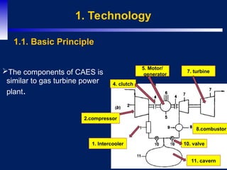
1. Technology
The componentsof CAES is
similar to gas turbine power
plant.
1.1. Basic Principle
2.compressor
7. turbine
11. cavern
5. Motor/
generator
1. Intercooler
8.combustor
4. clutch
10. valve
3.
3
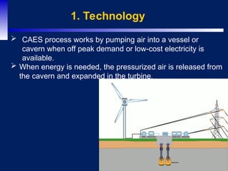
1. Technology
CAESprocess works by pumping air into a vessel or
cavern when off peak demand or low-cost electricity is
available.
When energy is needed, the pressurized air is released from
the cavern and expanded in the turbine.
5
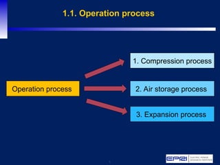
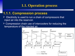
1.1. Operation process
Electricity is used to run a chain of compressors that
inject air into the reservoir.
Compression chain use of intercoolers for reducing the
temperature of the injected air.
1.1.1. Compression process
6.
6
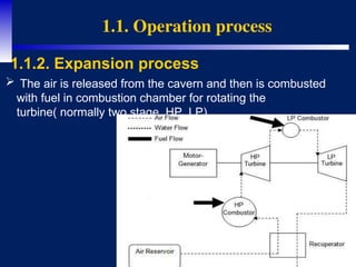
1.1. Operation process
1.1.2.Expansion process
The air is released from the cavern and then is combusted
with fuel in combustion chamber for rotating the
turbine( normally two stage, HP, LP).
7.
7
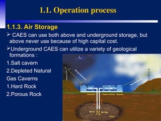
CAES canuse both above and underground storage, but
above never use because of high capital cost.
Underground CAES can utilize a variety of geological
formations :
1.Salt cavern
2.Depleted Natural
Gas Caverns
1.Hard Rock
2.Porous Rock
1.1. Operation process
1.1.3. Air Storage
8.
8
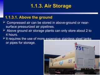
1.1.3. Air Storage
1.1.3.1.Above the ground
Compressed air can be stored in above-ground or near-
surface pressurized air pipelines.
Above ground air storage plants can only store about 2 to
4 hours.
It requires the use of more expensive stainless steel tanks
or pipes for storage.
9.
9
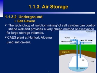
1.1.3. Air Storage
The technology of 'solution mining' of salt cavities can control
shape well and provides a very cheap method of excavation
for large storage volumes.
CAES plant at Huntorf, Albama
used salt cavern.
1.1.3.2. Underground
i. Salt Cavern
10.
10
1.3. Type ofCAES system
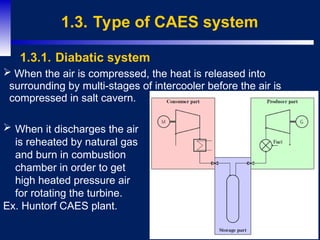
When the air is compressed, the heat is released into
surrounding by multi-stages of intercooler before the air is
compressed in salt cavern.
1.3.1. Diabatic system
When it discharges the air
is reheated by natural gas
and burn in combustion
chamber in order to get
high heated pressure air
for rotating the turbine.
Ex. Huntorf CAES plant.
11.
11
1.3. Type ofCAES system
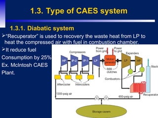
“Recuperator” is used to recovery the waste heat from LP to
heat the compressed air with fuel in combustion chamber.
It reduce fuel
Consumption by 25%.
Ex. McIntosh CAES
Plant.
1.3.1. Diabatic system
12.
12
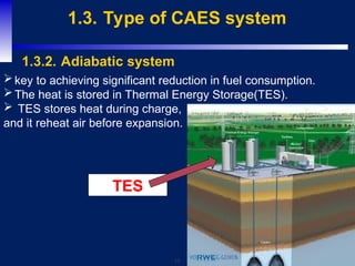
1.3. Type ofCAES system
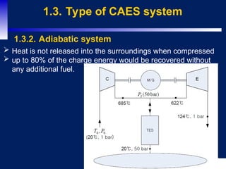
1.3.2. Adiabatic system
Heat is not released into the surroundings when compressed
up to 80% of the charge energy would be recovered without
any additional fuel.
13.
13
1.3. Type ofCAES system
1.3.2. Adiabatic system
key to achieving significant reduction in fuel consumption.
The heat is stored in Thermal Energy Storage(TES).
TES stores heat during charge,
and it reheat air before expansion.
TES
14.
14
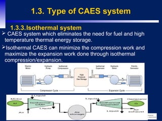
1.3. Type ofCAES system
CAES system which eliminates the need for fuel and high
temperature thermal energy storage.
Isothermal CAES can minimize the compression work and
maximize the expansion work done through isothermal
compression/expansion.
1.3.3.Isothermal system
15.
15
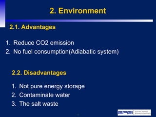
2. Environment
1. ReduceCO2 emission
2. No fuel consumption(Adiabatic system)
2.1. Advantages
1. Not pure energy storage
2. Contaminate water
3. The salt waste
2.2. Disadvantages
16.
16
5. Conclusion
AlthoughCAES has some problems such as location, not
pure energy.
CAES is still a good choice for storing energy due to its
capacity, capital cost, and potential.
According to new technology (Adiabatic), CAES will not
consume fuel any more.
Editor's Notes
#3 For more than a century, the technology for using falling water to create hydroelectricity has existed.
#6 The total worldwide technical potential for hydropower is estimated at 14,576 TWh/yr (52.47 EJ/yr), over four times the current worldwide annual generation. This technical potential corresponds to a derived estimate of installed capacity of 3,721 GW.
#9 Hydroelectric generation can also work without dams, in a process known as diversion, or run-of-the-river. Run-of-the-river hydroelectric stations are those with small or no reservoir capacity, so that the water coming from upstream must be used for generation at that moment, or must be allowed to bypass the dam.
Run-of-river schemes use the natural flow of a river, where a weir can enhance the continuity of the flow. Both storage and run-of-river schemes can be diversion schemes, where water is channeled from a river, lake or dammed reservoir to a remote powerhouse, containing the turbine
#10 Global installed hydropower capacity was estimated to be between 926 GW and 956 GW in 2009/2010, excluding pumped storage hydropower capacity.