Downloaded 572 times


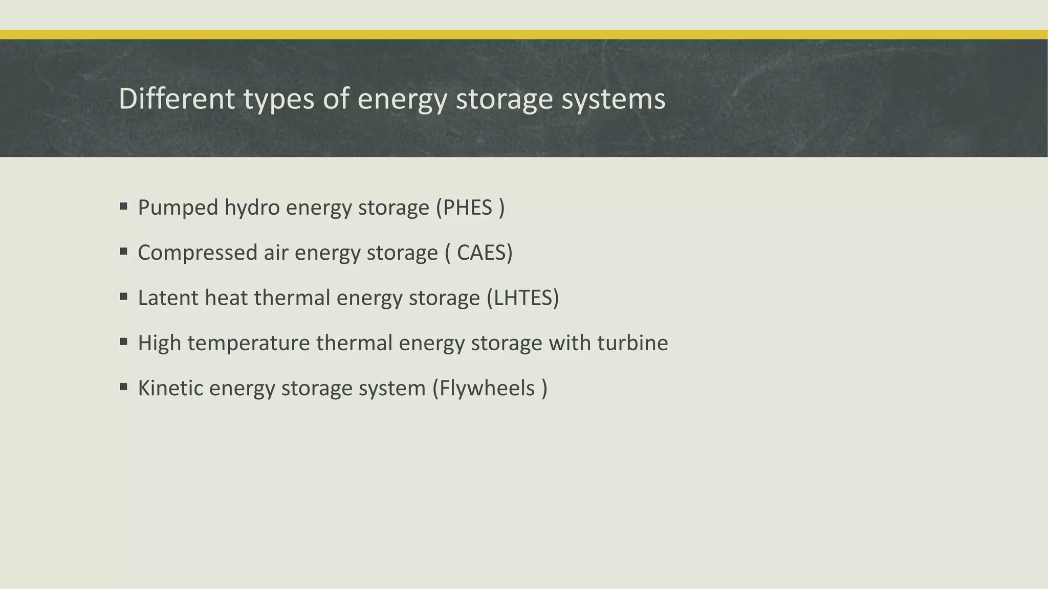
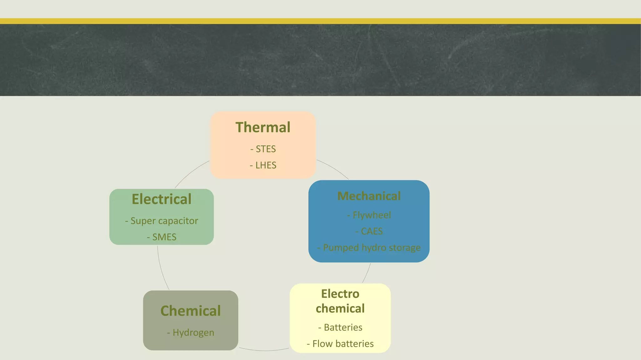


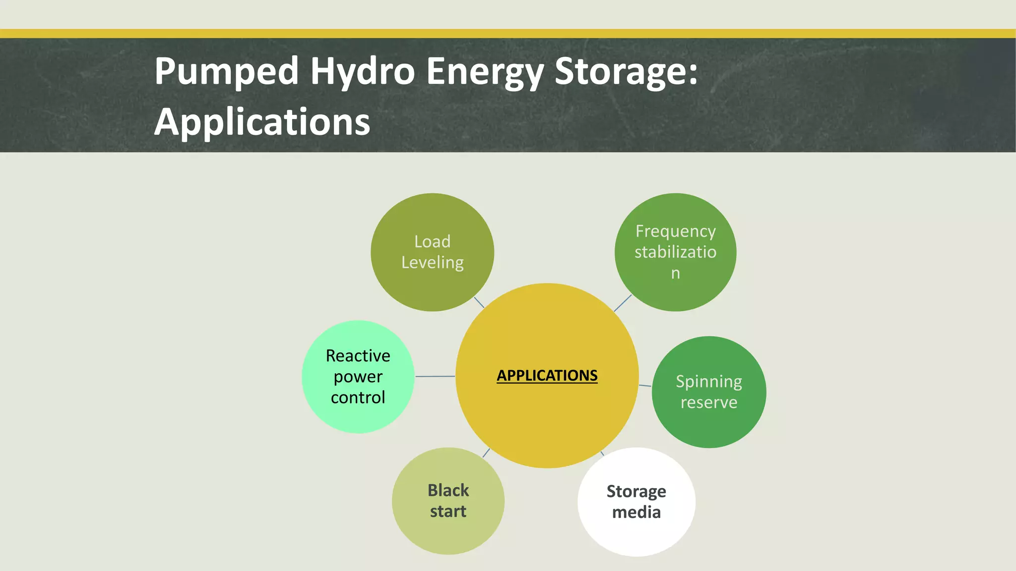

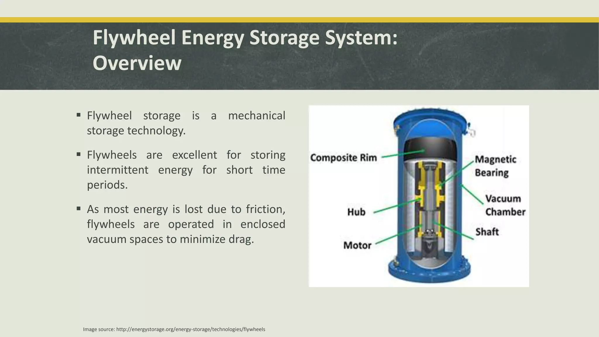
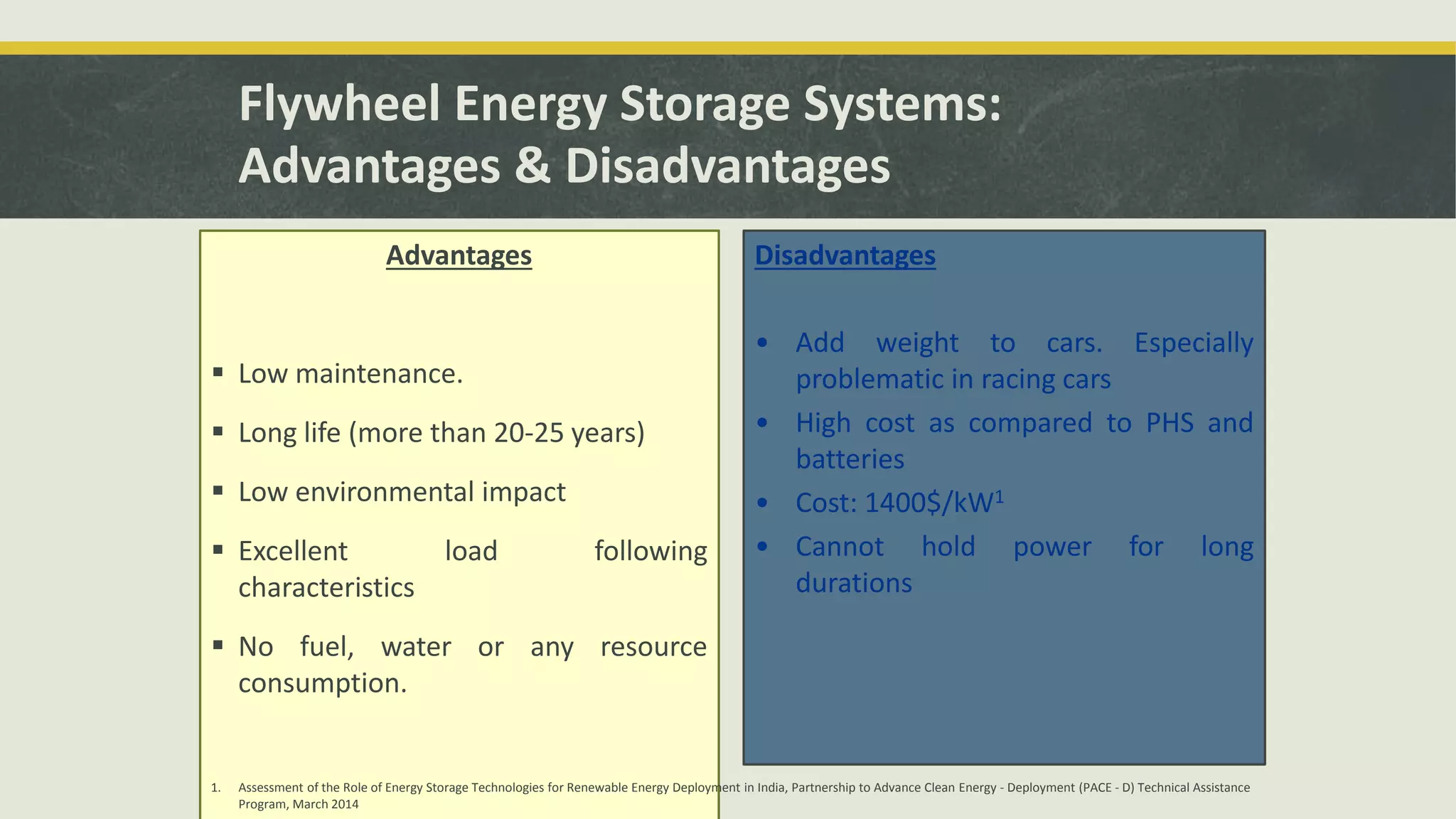

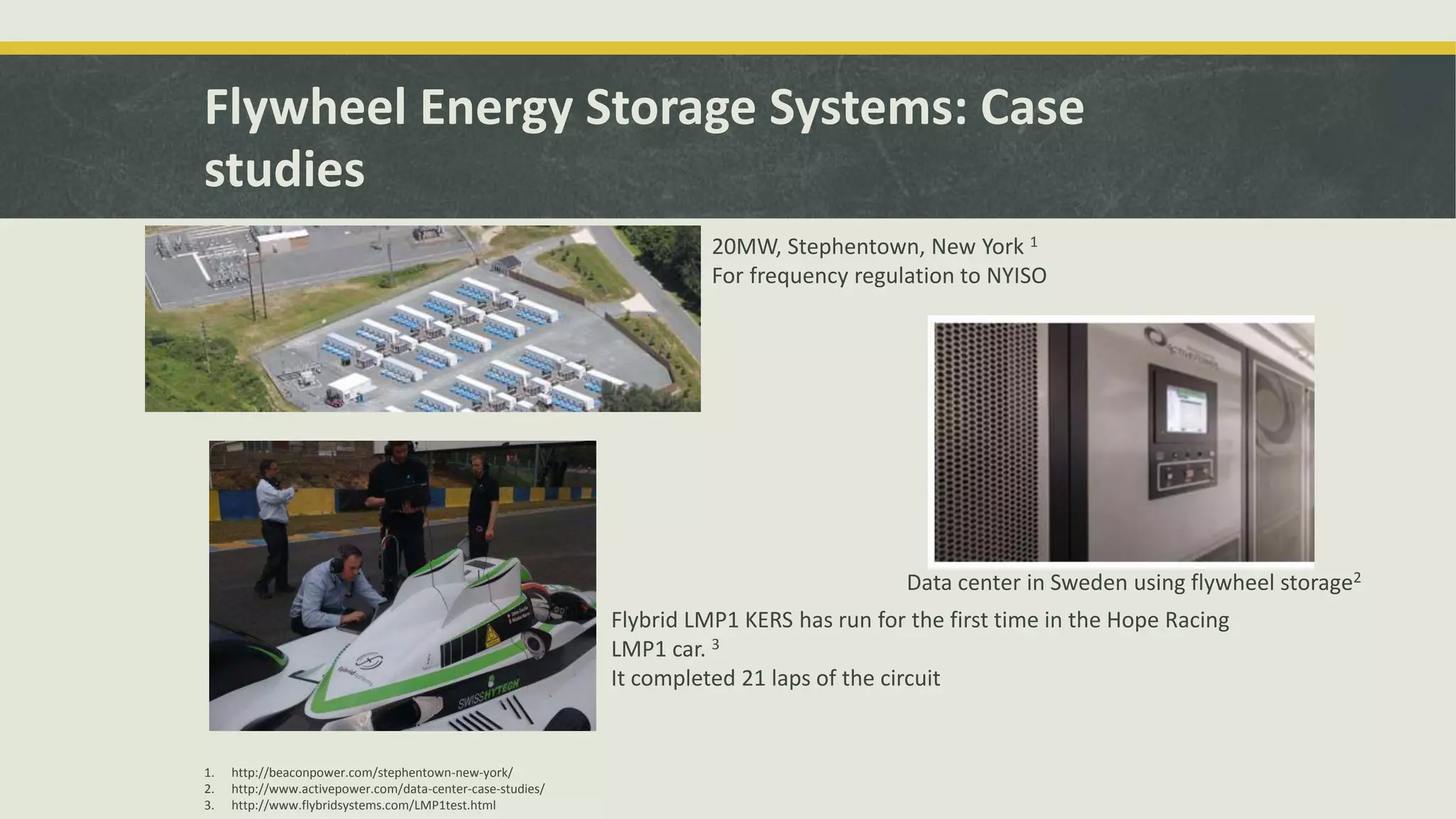


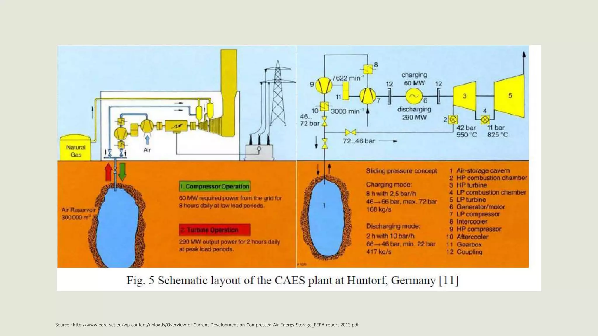
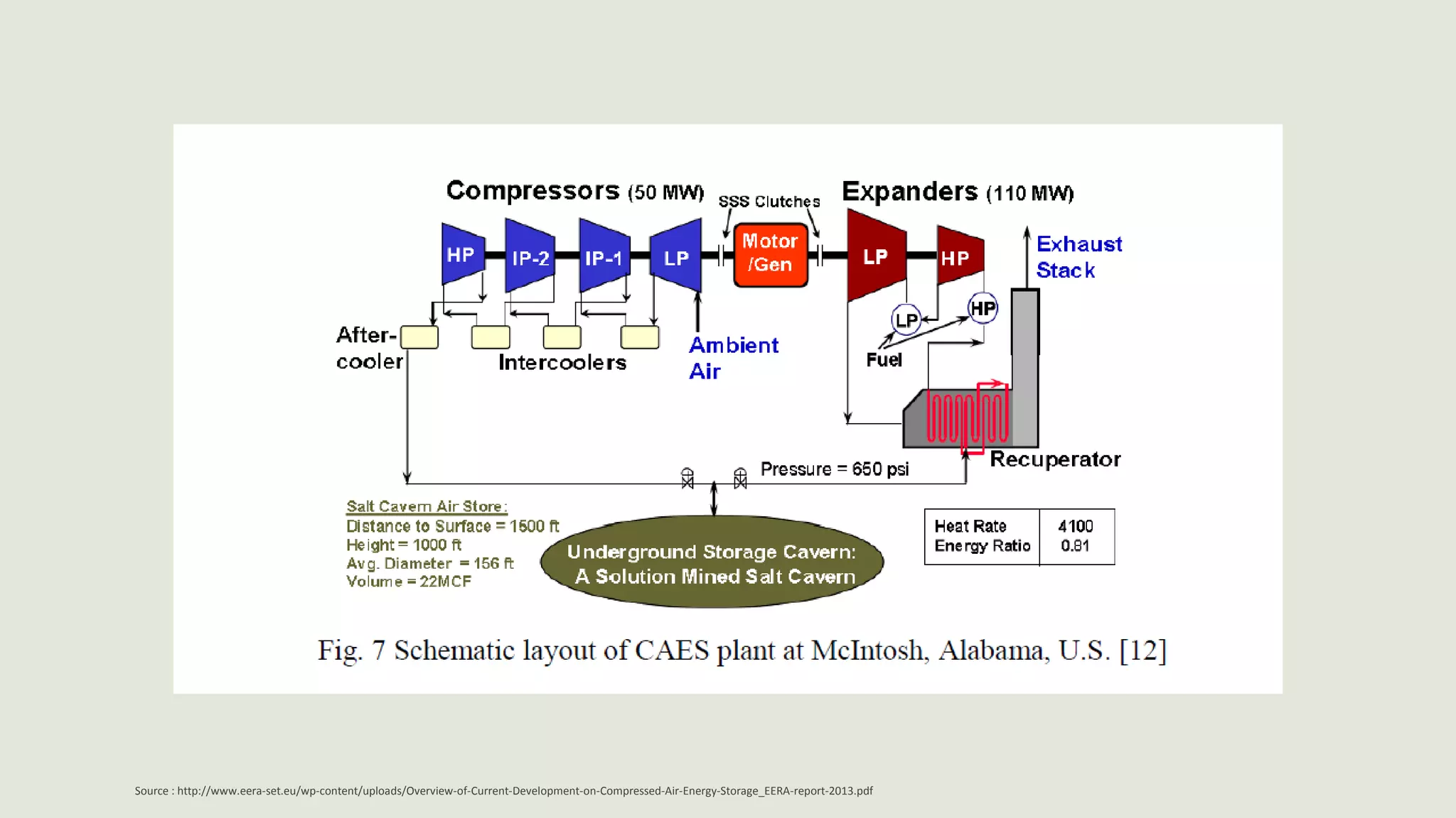


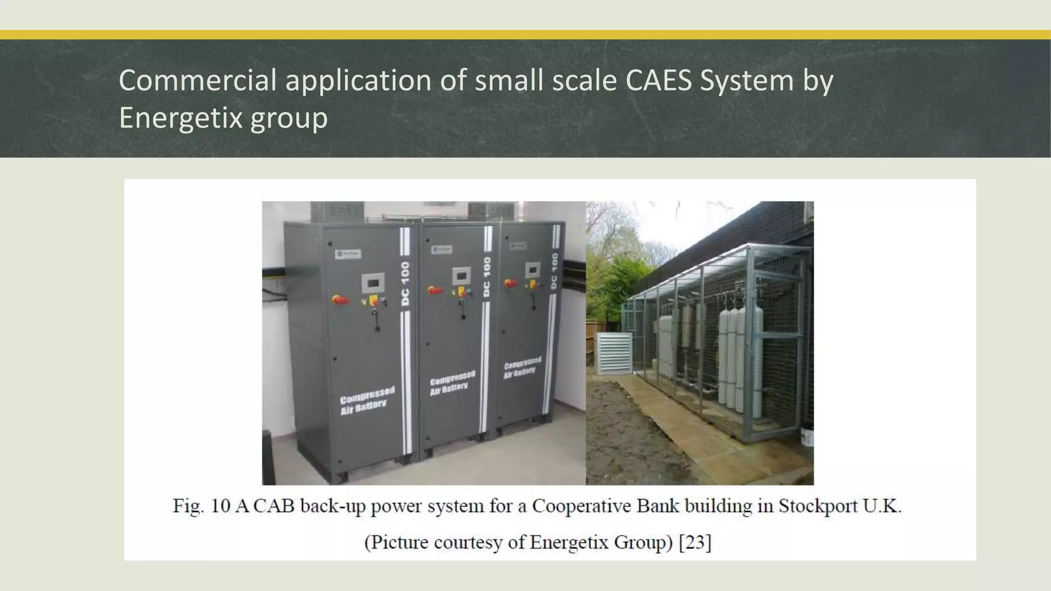

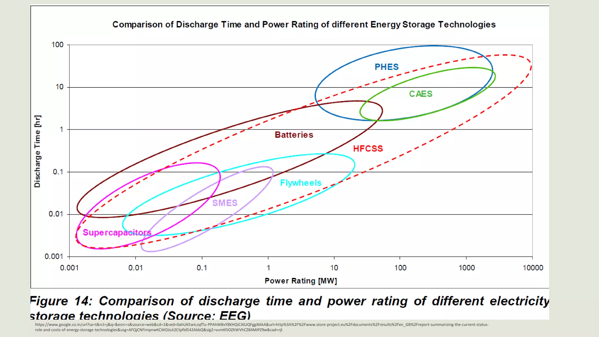
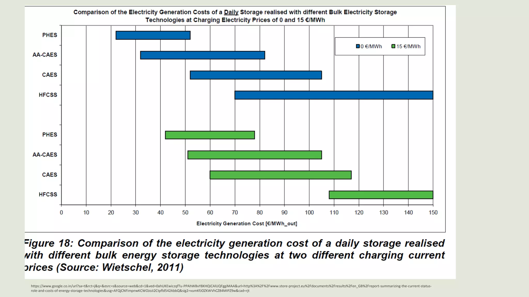


The document discusses various energy storage technologies including their applications and status. It provides an overview of pumped hydro energy storage, the most commercially developed technology which uses two water reservoirs at different heights. Compressed air energy storage is also discussed, which uses surplus electricity to compress air into underground storage, then releases it to power a turbine when needed. Flywheel energy storage uses rotating flywheels to store kinetic energy and is well-suited for applications requiring high power over short durations. The document examines the advantages, disadvantages and example projects for these various energy storage methods.