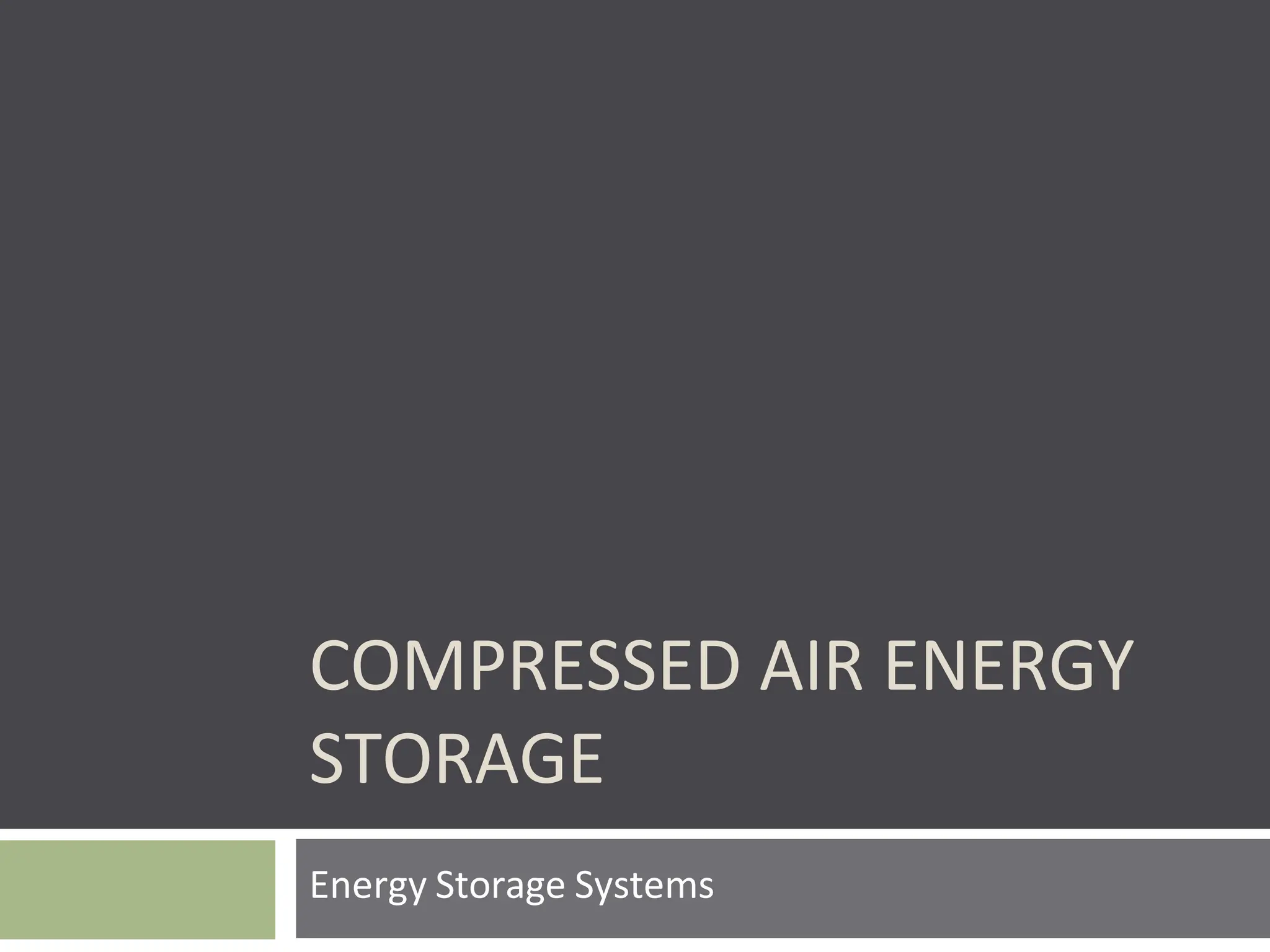
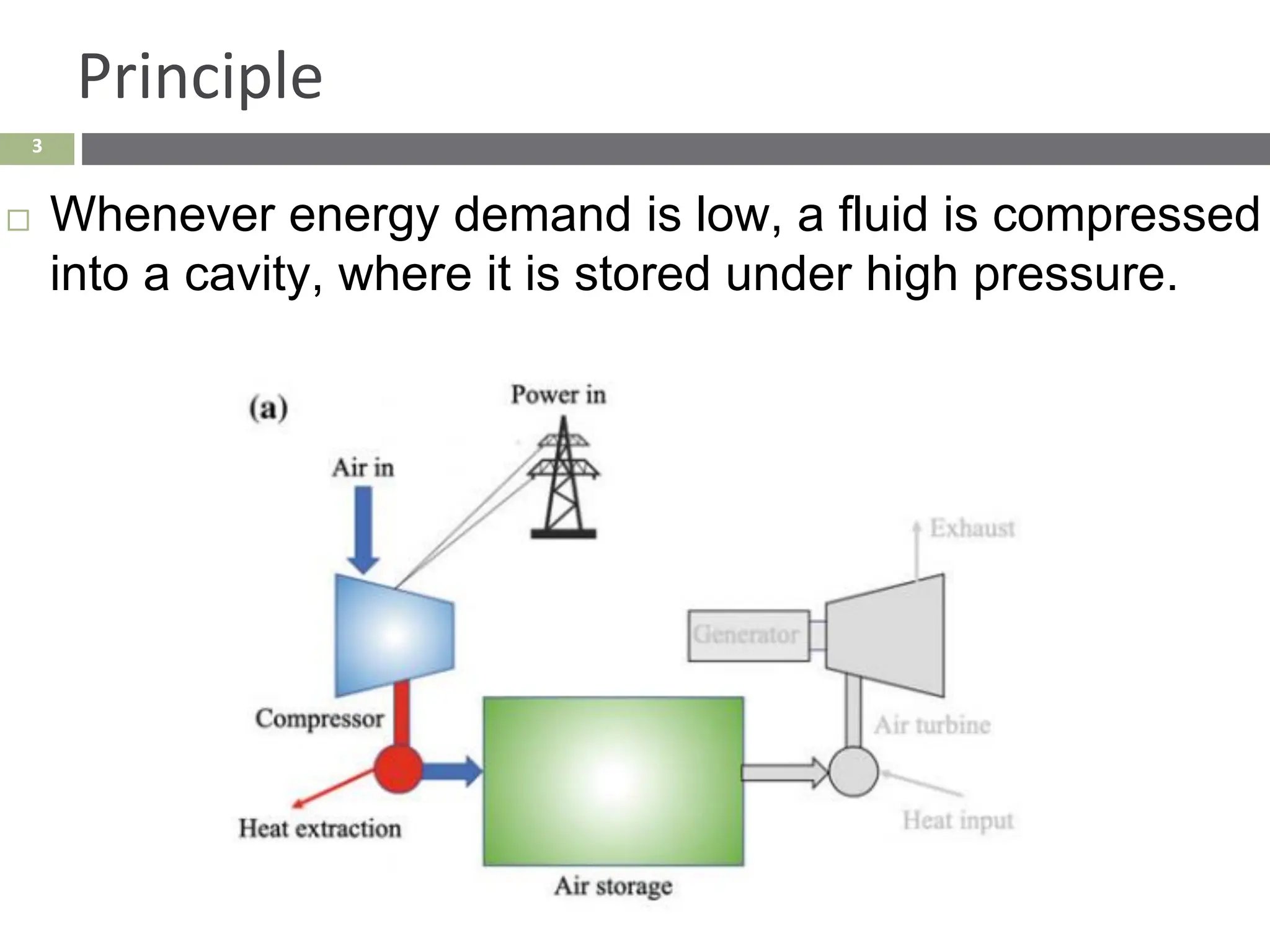
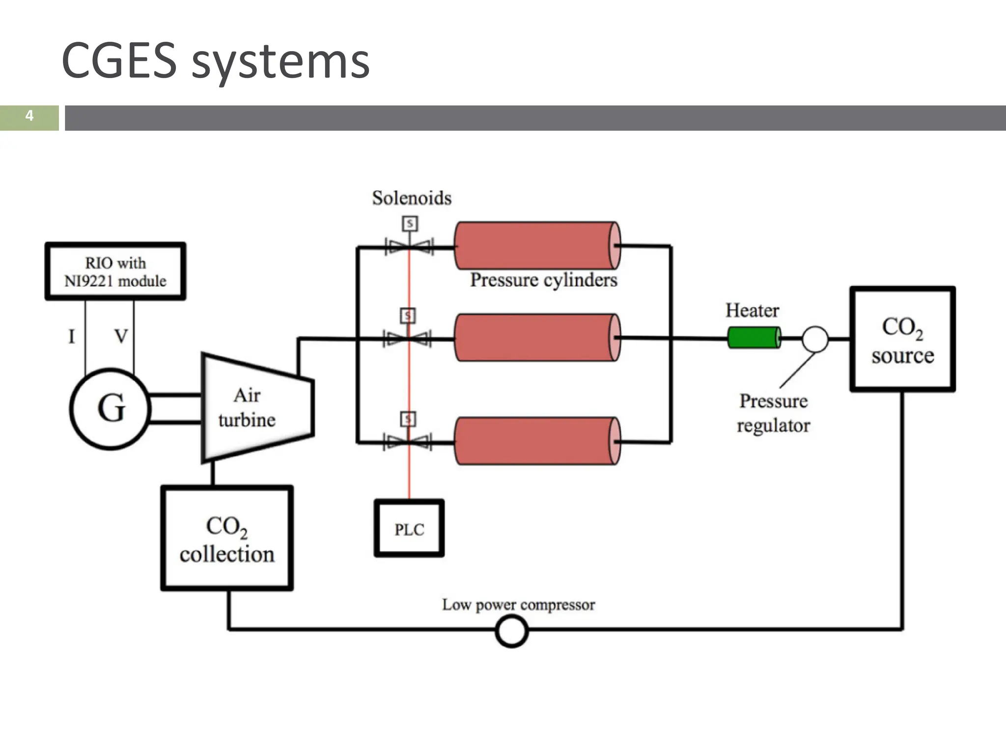
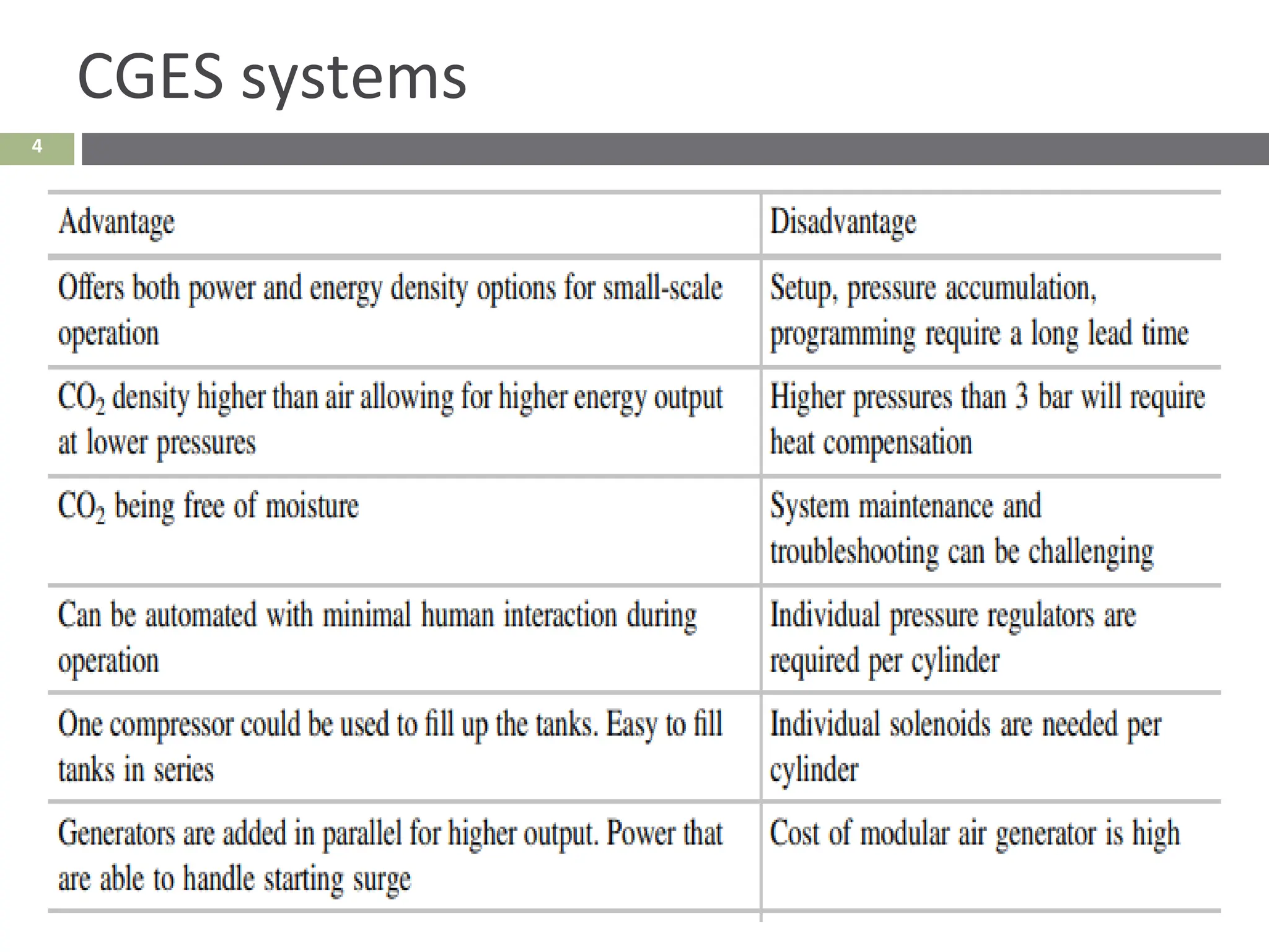
3. 3
Principle
Whenever energy demand is low, a fluid is compressed
into a cavity, where it is stored under high pressure.
4. 3
Principle
When the demand is high, the fluid is released into a
rotational energy extraction machine (an air turbine).
5. 4
Advantages
Relatively inexpensive.
Eco-friendly.
Mechanically simple.
Have high energy storage capacity.
In CGES, another gas (CO2, for example) is the working
fluid instead of air in a closed-loop cycle.
Here CO2 capture benefits can be coupled CAES
systems.
It benefits geology of the field after all oil is extracted
to prevent sinkholes from forming.
7. 5
History
• The first large CAES installation was a 290 MW plant at Huntorf,
Germany, in 1978.
• Compressed air is stored in underground depleted salt caverns
that can fill up in 8 h at a rate of 108 kg/s.
• In discharge mode, compressed air is released and heated up by
burning natural gas.
• The air drives a 320 MW turbine for two hours, after which the
caverns become depleted (the pressure remaining is not
enough to give high quality of energy) and have to be refilled.
9. 5
History
• The second major CAES plant is a 110 MW plant run by
PowerSouth Energy Cooperative in McIntosh Alabama.
• Became commercial in 1991 (only one of its kind in the U.S. ).
• During off-peak hours, air is pumped into the cavern in
“compression mode.”
• At full charge, air pressure in the cavern reaches nearly 1,100 lb
per square inch (7.5 MPa).
• During peak, the plant is put into “generation mode.”
• Air is released and fed into a heat exchanger called a Recuperator,
Where it is heated to approximately (315 °C).
• The main difference from Huntorf facility is that hot air enters a
high-pressure combustion chamber, where natural gas is used to
heat the air to (537 °C) before entering a high-pressure expander.
• The exhaust is re-heated to (871 °C) before entering a low-
pressure expander.
• Together, the high and low-pressure expanders produce enough
electricity to power nearly 110,000 homes for up to 26 h.
10. 6
Air compressor
• The Huntorf power plant uses axial flow and centrifugal
multistage compression with inter-stage and post-stage
cooling.
• For smaller CAES systems, it could be more suitable to
use a single-stage or multistage reciprocating compressor
to reduce the volume of the gas storage device and
ensure higher pressure values in storage
11. 6
Expander
• The sudden depressurization of the stored air entails great
losses.
• It is beneficial to have expansion that takes place in stages.
• The Huntorf power station uses a modified steam turbine as
its first stage to contend with the expansion of air from high
storage pressures.
• Small CAES systems would use micro gas turbine
components, reciprocating expanders, or screw air engines,
which are less efficient.
12. 4
Reservoirs
Just like PHES, CAES systems benefit from the
existence of underground reservoirs that are both
cavernous and impermeable.
Depleted natural salt mines, as well as depleted oil and
gas fields are perfect candidates for such major
storage space.
They have natural impenetrability to fluid penetration
such that air can be compressed with little leakage.
This guaranteed that high levels of pressure storage
are attainable and sustainable.
13. 6
Thermal Storage System
• Heat exchangers with high effectiveness, are required for the
heat generated due to air/gas pressurization, and the counter
phenomenon of freezing during depressurization.
• The selected heat exchangers need to be:
❑ Airtight
❑ allow low heat loss,
❑ adaptable to the working range at an economical cost.
14. 7
Classification of CAES Systems
1) According to Size and Scale:
❑ Large-scale CAES (>100 MW): are used in conjunction
with utilities power grid applications.
❑ Small-scale CAES (from a few MW to kW): are mainly
used for renewable energy applications.
❑ Microscale CAES (*10 kW): can be used for military
❑ applications and as backup power supplies. Can also
❑ be found in pneumatic vehicle applications and
household power grids.
15. 7
Classification of CAES Systems
2) According to Heat Generation Handling:
❑ The heat generated during air or gas compression reduces
the compression efficiency, as the relationship between the
power and the pressure is nonlinear,
❑ This highlights the benefits of using multistage
compression.
16. 7
Classification of CAES Systems
2) According to Heat Generation Handling:
A) D-CAES (diabatic) systems:
➢ Assumes that there are no heat exchangers associated with
the facility.
➢ During compression, heat is transferred directly to the
➢ surroundings, thereby causing waste.
➢ Requires an external heat source during expansion to
prevent condensation, or worse, freezing in the air turbine
stage.
➢ To provide this external heat, fossil fuel must be burnt.
17. 7
Classification of CAES Systems
2) According to Heat Generation Handling:
B) A-CAES (Adiabatic) systems:
➢ Are the most widely used design approach.
➢ The heat generated by compression is transferred and
stored in a thermal energy storage (TES) system, which is
later utilized during the expansion process.
➢ There are also Advanced A-CAES (AA-CAES) technologies
that have been available quite recently (since 2015) that
uses state-of-the-art ceramic heat exchangers to provide
the required high heat transfer efficiencies
18. 7
Classification of CAES Systems
2) According to Heat Generation Handling:
C) I-CAES (Isothermal) systems:
➢ Are still under development and require specialized machines
to handle the heat exchange.
➢ The temperature rise of the compressed gas is assumed to
rise in quasi-equilibrium steps, where heat is transferred
almost instantaneously, thereby preventing the compression
temperature rise and expansion temperature drop.
➢ Is yet to be applied in industrial CAES installations.
20. 7
Governing Equations
Can also be written in terms of the Mach number, M.
Mach number is the ratio of the flow velocity, v, over the speed of
sound, a.
The critical area, A* , the minimum cross-sectional area of the
expansion nozzle, can also be calculated as:
21. 7
Governing Equations
❑ Work in terms of starting and terminal pressures P1 and
❑ P2, respectively, and the volume of the storage reservoir, can be
calculated from:
Since adiabatic conditions are assumed to hold, a simplified form
of the energy equations is applied between points 1 and 2 to
estimate the maximum exit velocity of air from the nozzle to be:
22. 7
Governing Equations
❑ Work in terms of starting and terminal pressures P1 and
❑ P2, respectively, and the volume of the storage reservoir, can be
calculated from:
Since adiabatic conditions are assumed to hold, a simplified form
of the energy equations is applied between points 1 and 2 to
estimate the maximum exit velocity of air from the nozzle to be:
where rho ave is the average air density between states 1 and 2
23. 7
Governing Equations
assuming a linear pressure drop during system discharge. The
overall CAES system efficiency as a function of the pressure ratio
P* is given as:
The electrical conversion efficiency of the system is taken as the
ratio of the electrical output power over the stored pressure
potential (P times the total volume of the cylinder) as:
24. 7
Governing Equations
Finally, the mechanical efficiency of the system is defined as:
where I is the moment of inertia of the generator rotor, and w
is its angular velocity in rad/s
25. 4
CGES systems
In CGES, another gas (CO2, for example) is the working
fluid instead of air in a closed-loop cycle.
Here CO2 capture benefits can be coupled CAES
systems.
It benefits geology of the field after all oil is extracted
to prevent sinkholes from forming.