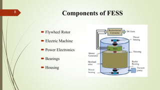
FLYWHEEL ENERGY STORAGE SYSTEM
GUIDED BY
Mr. VISHNU PRATHAP
ASSISTANT PROFESSOR
MECHANICAL DEPARTMENT
1
PRESENTED BY
ARUN ASOKAN
REG NO: 14005265
ROLL NO: 15
1
CONTENTS
 Introduction
 Literature Review
 Flywheel Energy Storage System(FESS)
 Component of FESS
 FESS in Porsche 911
 FESS in transportation
 FESS in railway
 FESS in spacecraft
 Advantages
 Limitations
 Conclusion
 References
2
INTRODUCTION
 Energy storage is becoming increasingly important to accommodate the
energy needs of a greater population.
 Conventional storage system is Uninterruptible Power Supply(UPS) system.
 UPS system is based on the lead-acid battery.
 Flywheel Energy Storage System(FES) can represent a clean substitution
technology for conventional UPS system.
3
LITERATURE REVIEW4
SL.
NO
TITLE OF THE
JOURNAL (YEAR)
AUTHOR NAME,
JOURNAL NAME
MAIN POINTS
1 A comprehensive
review of Flywheel
Energy Storage System
technology
(2017)
S.M. Mousavi G,Faramarz
Faraji , Abbas Majazi &
Kamal Al-
Haddad,
Renewable and
Sustainable Energy
Reviews
• The typical overview of FESS operation
as an electric supply charges the flywheel
that stores energy in the form of kinetic
energy.
• Comprehensive review of FESS in
different applications
2 A Review of Flywheel
Energy Storage System
Technologies and Their
Applications
(2017)
Mustafa E. Amiryar &
Keith R. Pullen,
Applied Science
• Critical review of FESS with reference to
its main components
• The main applications of FESS in
transportation, railway and space are
explained
LITERATURE REVIEW5
SL.
NO
TITLE OF THE JOURNAL
(YEAR)
AUTHOR NAME,
JOURNAL NAME
MAIN POINTS
3 Design and Analysis of a
Unique
Energy Storage Flywheel
System—An Integrated
Flywheel, Motor/Generator,
and Magnetic Bearing
Configuration
(2015)
Arunvel Kailasan,
Tim Dimond,
Paul Allaire&
David Sheffler,
Journal of
Engineering for Gas
Turbines and Power
• Design of the composite rotor is studied
• A three-dimensional analysis was done on
the entire structure.
• The different parameters of the magnetic
bearing are calculated.
Flywheel Energy Storage System(FESS)
 A flywheel stores energy in a rotating mass, depending on the
inertia and speed of the rotating mass.
 According on the need of the grid, the kinetic energy is transferred
either in or out of the flywheel.
6
Flywheel Energy Storage System(FESS)
 Flywheel is connected to a machine that works as either the motor or
generator.
 The energy conversion in a FESS is accomplished by the electrical
machine and a bi-directional power converter.
7
Components of FESS8
 Flywheel Rotor
 Electric Machine
 Power Electronics
 Bearings
 Housing
FLYWHEEL ROTOR
 The energy stored in flywheel is given by
E = ½ I ω ^2
where E is the stored kinetic energy, I is the moment of inertia,
and ω is the angular velocity.
 The maximum specific energy is given by
where σ is the maximum stress, ρ is the density of the flywheel and
K is the shape factor
9
FLYWHEEL ROTOR
 The stored energy can be optimized either by increasing the
spinning speed (ω) or increasing the moment of inertia (I).
 Two type FESS
Low Speed FESS
High speed FESS
10
ELETRIC MACHINE
 The electrical machine is coupled to the flywheel to enable the
energy conversion and charging process.
 The machine acting as a motor, charges the flywheel by accelerating
it and drawing electrical energy from the source.
 The stored energy on the flywheel is extracted by the same machine,
acting as a generator.
 Common electrical machines used in FESS are
 Induction Machine(IM)
Variable Reluctant Machine (VRM)
 Permanent Magnet Machine (PM)
11
POWER ELECTRONICS
 The energy conversion in a FESS is accomplished by the electrical
machine and a bi-directional power converter.
 The power electronic converter topologies that can be used for FESS
applications are
DC-AC
AC-AC
 AC-DC-AC
 The widely used configuration of power converters in FESS is
AC-DC-AC configuration
12
BEARINGS
 Bearings are required to keep the rotor in place with very low
friction to provide a support mechanism for the flywheel.
 Different type of bearing systems are
Mechanical bearing
Magnetic bearing
 The widely used bearing technology is magnetic bearing.
13
HOUSING
 The housing has two purposes
To provide an environment for low gas drag.
For the containment of the rotor in the event of a failure.
 The housing or enclosure is the stationary part of the flywheel and is
usually made of a thick steel or other high strength material.
 The container holds the rotor in a vacuum to control rotor
aerodynamic drag losses by maintaining the low pressure inside the
device.
14
FESS in Porsche 91115
 The battery based electric vehicle was replaced with the flywheel
concept.
 Increase the fuel-efficiency and eco-consciousness of the vehicle.
 Energy wasted while braking is converted into stored energy by
flywheel.
FESS IN TRANSPORTATION
 Flywheels are used in hybrid and electric vehicles to store energy,
for use when harsh acceleration is required or to assist with uphill
climbs.
 Energy from regenerative braking during vehicle slowdown is stored
in flywheels.
 In electrical vehicles with chemical batteries as their source of
propulsion, flywheels are considered to cope well with a fluctuating
power consumption.
16
FESS IN SPACECRAFT17
FESS IN SPACECRAFT
 In space vehicles where the primary source of energy is the sun, and
where the energy needs to be stored for the periods when the
satellite is in darkness.
 Initially designs used battery storage, but now FESS are being
considered in combination with or to replace batteries.
 FESS is the only storage system that can accomplish dual functions,
by providing satellites with renewable energy storage in conjunction
with attitude control.
18
FESS IN RAILWAY
 The reuse of regenerative energy from vehicle braking is the
important benefit of using energy storage in electrical railways.
 It can increase electrical railway energy efficiency.
 Regenerative brake decelerates the train by changing its kinetic
energy into electricity and it can be fed back to the power grid in a
short time or stored until required.
19
ADVATNAGES
 Flywheels are not as adversely affected by temperature changes.
 High power capability
 Instant response
 Working lifespan is high.
 They are also less potentially damaging to the environment.
 It is possible to know the exact amount of energy stored by a simple
measurement of rotation speed.
20
LIMITATIONS
 Primary limits of flywheel design is the tensile strength of the
material used for rotor.
 Traditional flywheel systems require strong containment vessels as a
safety precaution.
 FESS using mechanical bearing can lose 20% to 50% of their
energy in 2hours.
21
CONCLUSION
 Flywheels are one of the most promising technologies for replacing
conventional lead acid batteries as energy storage systems for a
variety of applications.
 The main components flywheel rotor, electric machines, power
electronics, and bearing systems for flywheel storage systems are
described.
22
CONCLUSION
 The main applications of FESS in transportation, railway and space
are explained.
 FESS offer the unique characteristics of a very high cycle and
lifespan.
 Future work will include the detailed modelling and analysis of a
flywheel system for backup power and grid support applications.
23
REFERENCE
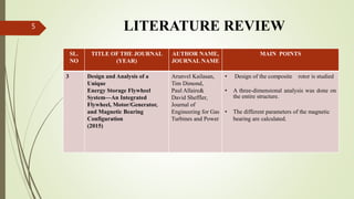
Arunvel Kailasan,Tim Dimond,Paul Allaire&Da Sheffler, Design and Analysis
of a Unique Energy Storage Flywheel System—An Integrated Flywheel,
Motor/Generator,and Magnetic BearingConfiguration/Journal of Engineering
for Gas Turbines and Power APRIL 2015, Vol. 137 / 042505
Mustafa E. Amiryar & Keith R. Pullen, A Review of Flywheel Energy Storage
System Technologies and Their Applications/Applied Science Appl. Sci.
2017,Vol.286,7
S.M. Mousavi G et al, Renewable and Sustainable Energy Reviews /Renewable
and Sustainable Energy Reviews 67(2017)477–490
24
[1]
[2]
[3]
THANKYOU…..
25
26

Fly wheel energy storage system

  • 1.
    FLYWHEEL ENERGY STORAGESYSTEM GUIDED BY Mr. VISHNU PRATHAP ASSISTANT PROFESSOR MECHANICAL DEPARTMENT 1 PRESENTED BY ARUN ASOKAN REG NO: 14005265 ROLL NO: 15 1
  • 2.
    CONTENTS  Introduction  LiteratureReview  Flywheel Energy Storage System(FESS)  Component of FESS  FESS in Porsche 911  FESS in transportation  FESS in railway  FESS in spacecraft  Advantages  Limitations  Conclusion  References 2
  • 3.
    INTRODUCTION  Energy storageis becoming increasingly important to accommodate the energy needs of a greater population.  Conventional storage system is Uninterruptible Power Supply(UPS) system.  UPS system is based on the lead-acid battery.  Flywheel Energy Storage System(FES) can represent a clean substitution technology for conventional UPS system. 3
  • 4.
    LITERATURE REVIEW4 SL. NO TITLE OFTHE JOURNAL (YEAR) AUTHOR NAME, JOURNAL NAME MAIN POINTS 1 A comprehensive review of Flywheel Energy Storage System technology (2017) S.M. Mousavi G,Faramarz Faraji , Abbas Majazi & Kamal Al- Haddad, Renewable and Sustainable Energy Reviews • The typical overview of FESS operation as an electric supply charges the flywheel that stores energy in the form of kinetic energy. • Comprehensive review of FESS in different applications 2 A Review of Flywheel Energy Storage System Technologies and Their Applications (2017) Mustafa E. Amiryar & Keith R. Pullen, Applied Science • Critical review of FESS with reference to its main components • The main applications of FESS in transportation, railway and space are explained
  • 5.
    LITERATURE REVIEW5 SL. NO TITLE OFTHE JOURNAL (YEAR) AUTHOR NAME, JOURNAL NAME MAIN POINTS 3 Design and Analysis of a Unique Energy Storage Flywheel System—An Integrated Flywheel, Motor/Generator, and Magnetic Bearing Configuration (2015) Arunvel Kailasan, Tim Dimond, Paul Allaire& David Sheffler, Journal of Engineering for Gas Turbines and Power • Design of the composite rotor is studied • A three-dimensional analysis was done on the entire structure. • The different parameters of the magnetic bearing are calculated.
  • 6.
    Flywheel Energy StorageSystem(FESS)  A flywheel stores energy in a rotating mass, depending on the inertia and speed of the rotating mass.  According on the need of the grid, the kinetic energy is transferred either in or out of the flywheel. 6
  • 7.
    Flywheel Energy StorageSystem(FESS)  Flywheel is connected to a machine that works as either the motor or generator.  The energy conversion in a FESS is accomplished by the electrical machine and a bi-directional power converter. 7
  • 8.
    Components of FESS8 Flywheel Rotor  Electric Machine  Power Electronics  Bearings  Housing
  • 9.
    FLYWHEEL ROTOR  Theenergy stored in flywheel is given by E = ½ I ω ^2 where E is the stored kinetic energy, I is the moment of inertia, and ω is the angular velocity.  The maximum specific energy is given by where σ is the maximum stress, ρ is the density of the flywheel and K is the shape factor 9
  • 10.
    FLYWHEEL ROTOR  Thestored energy can be optimized either by increasing the spinning speed (ω) or increasing the moment of inertia (I).  Two type FESS Low Speed FESS High speed FESS 10
  • 11.
    ELETRIC MACHINE  Theelectrical machine is coupled to the flywheel to enable the energy conversion and charging process.  The machine acting as a motor, charges the flywheel by accelerating it and drawing electrical energy from the source.  The stored energy on the flywheel is extracted by the same machine, acting as a generator.  Common electrical machines used in FESS are  Induction Machine(IM) Variable Reluctant Machine (VRM)  Permanent Magnet Machine (PM) 11
  • 12.
    POWER ELECTRONICS  Theenergy conversion in a FESS is accomplished by the electrical machine and a bi-directional power converter.  The power electronic converter topologies that can be used for FESS applications are DC-AC AC-AC  AC-DC-AC  The widely used configuration of power converters in FESS is AC-DC-AC configuration 12
  • 13.
    BEARINGS  Bearings arerequired to keep the rotor in place with very low friction to provide a support mechanism for the flywheel.  Different type of bearing systems are Mechanical bearing Magnetic bearing  The widely used bearing technology is magnetic bearing. 13
  • 14.
    HOUSING  The housinghas two purposes To provide an environment for low gas drag. For the containment of the rotor in the event of a failure.  The housing or enclosure is the stationary part of the flywheel and is usually made of a thick steel or other high strength material.  The container holds the rotor in a vacuum to control rotor aerodynamic drag losses by maintaining the low pressure inside the device. 14
  • 15.
    FESS in Porsche91115  The battery based electric vehicle was replaced with the flywheel concept.  Increase the fuel-efficiency and eco-consciousness of the vehicle.  Energy wasted while braking is converted into stored energy by flywheel.
  • 16.
    FESS IN TRANSPORTATION Flywheels are used in hybrid and electric vehicles to store energy, for use when harsh acceleration is required or to assist with uphill climbs.  Energy from regenerative braking during vehicle slowdown is stored in flywheels.  In electrical vehicles with chemical batteries as their source of propulsion, flywheels are considered to cope well with a fluctuating power consumption. 16
  • 17.
  • 18.
    FESS IN SPACECRAFT In space vehicles where the primary source of energy is the sun, and where the energy needs to be stored for the periods when the satellite is in darkness.  Initially designs used battery storage, but now FESS are being considered in combination with or to replace batteries.  FESS is the only storage system that can accomplish dual functions, by providing satellites with renewable energy storage in conjunction with attitude control. 18
  • 19.
    FESS IN RAILWAY The reuse of regenerative energy from vehicle braking is the important benefit of using energy storage in electrical railways.  It can increase electrical railway energy efficiency.  Regenerative brake decelerates the train by changing its kinetic energy into electricity and it can be fed back to the power grid in a short time or stored until required. 19
  • 20.
    ADVATNAGES  Flywheels arenot as adversely affected by temperature changes.  High power capability  Instant response  Working lifespan is high.  They are also less potentially damaging to the environment.  It is possible to know the exact amount of energy stored by a simple measurement of rotation speed. 20
  • 21.
    LIMITATIONS  Primary limitsof flywheel design is the tensile strength of the material used for rotor.  Traditional flywheel systems require strong containment vessels as a safety precaution.  FESS using mechanical bearing can lose 20% to 50% of their energy in 2hours. 21
  • 22.
    CONCLUSION  Flywheels areone of the most promising technologies for replacing conventional lead acid batteries as energy storage systems for a variety of applications.  The main components flywheel rotor, electric machines, power electronics, and bearing systems for flywheel storage systems are described. 22
  • 23.
    CONCLUSION  The mainapplications of FESS in transportation, railway and space are explained.  FESS offer the unique characteristics of a very high cycle and lifespan.  Future work will include the detailed modelling and analysis of a flywheel system for backup power and grid support applications. 23
  • 24.
    REFERENCE Arunvel Kailasan,Tim Dimond,PaulAllaire&Da Sheffler, Design and Analysis of a Unique Energy Storage Flywheel System—An Integrated Flywheel, Motor/Generator,and Magnetic BearingConfiguration/Journal of Engineering for Gas Turbines and Power APRIL 2015, Vol. 137 / 042505 Mustafa E. Amiryar & Keith R. Pullen, A Review of Flywheel Energy Storage System Technologies and Their Applications/Applied Science Appl. Sci. 2017,Vol.286,7 S.M. Mousavi G et al, Renewable and Sustainable Energy Reviews /Renewable and Sustainable Energy Reviews 67(2017)477–490 24 [1] [2] [3]
  • 25.
  • 26.

Editor's Notes

  • #9 A thrust bearing is a particular type of rotary bearing. Like otherbearings they permit rotation between parts, but they are designed to support a predominately axial load.
  • #16 The 24-hour Nurburgring race this May is all set to welcome Porsche’s new 911 GT3 R Hybrid vehicle powered by an electric engine and a 480 hp gas engine. Now the battery based electric vehicle was replaced with the flywheel concept to further add to the fuel-efficiency and eco-consciousness of the vehicle. Yet again the energy wasted while barking is converted into stored energy by flywheel and then released to give a 160 hp boost to the vehicle which lasts for about 6-8 seconds.