Downloaded 1,222 times

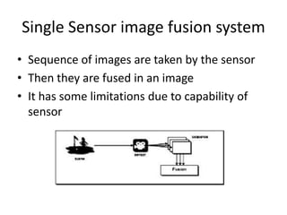
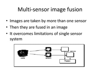

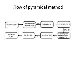
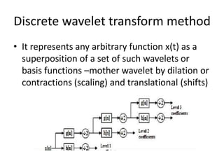
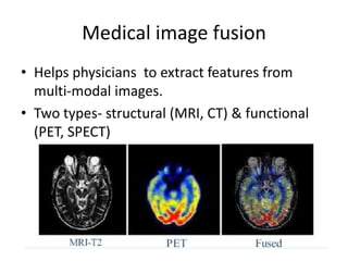
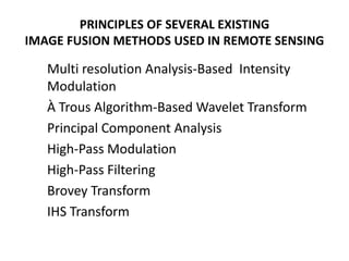
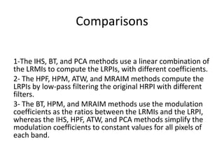
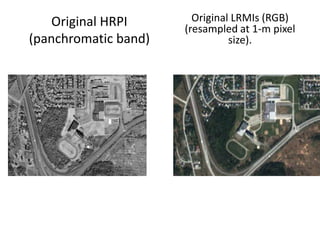
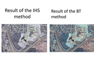
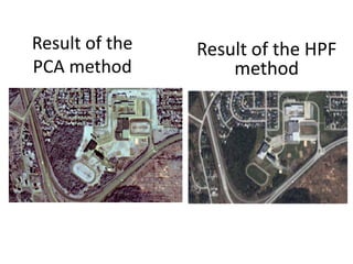
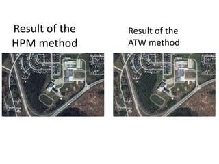
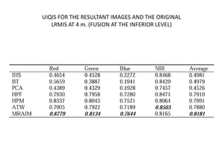


This document summarizes different techniques for fusing images from multiple sensors. It discusses how image fusion aims to reduce data volume while retaining important information. Single-sensor fusion involves fusing sequential images, while multi-sensor fusion overcomes single-sensor limitations. Key steps in image fusion systems include registration, preprocessing, and postprocessing. Common fusion methods discussed are in the spatial domain (e.g. weighted averaging, Brovey transform) and transform domain (e.g. discrete wavelet transform). The document evaluates different fusion methods for applications like remote sensing and medical imaging, finding the multiresolution analysis-based intensity modulation method most accurately reproduces high-resolution images.


![Getting Started with Apache Spark: Big Data Made Simple [Free Meetup]](https://cdn.slidesharecdn.com/ss_thumbnails/apachesparkgettingstarted-260203175547-8361bcc3-thumbnail.jpg?width=640&height=640&fit=bounds)
