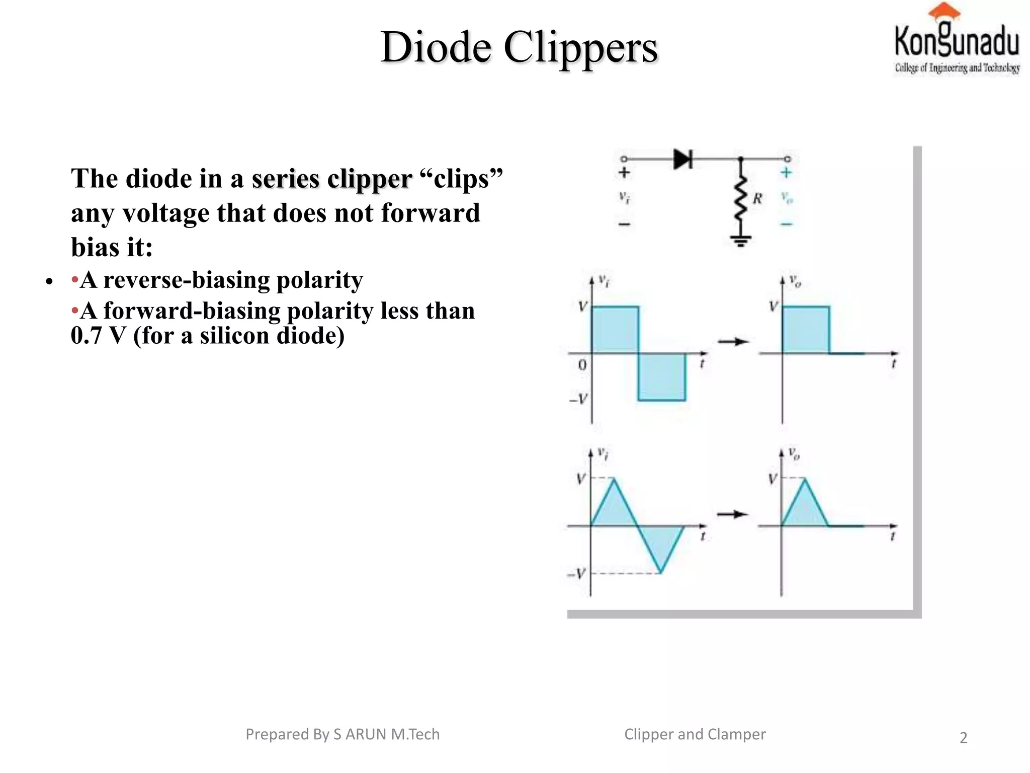
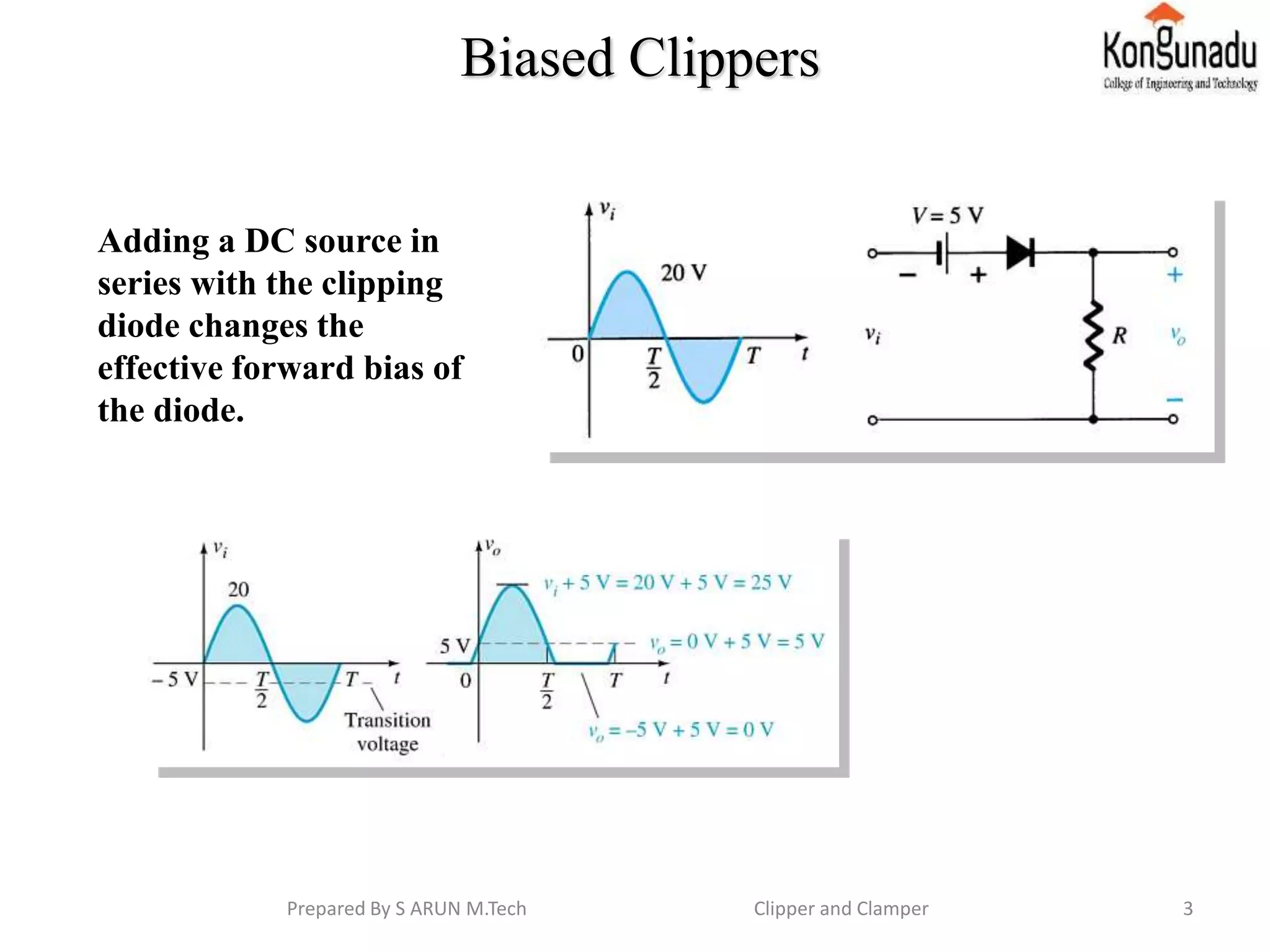
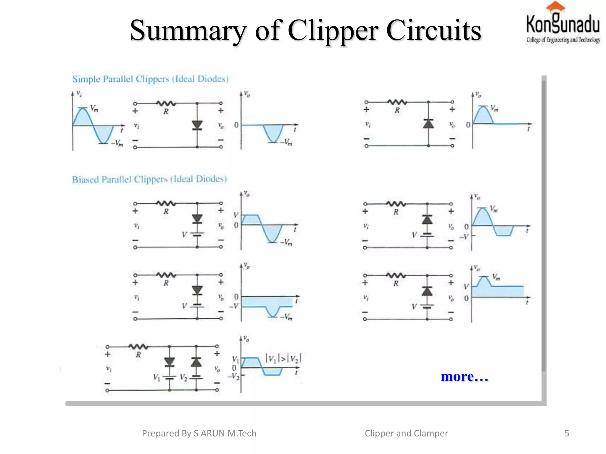
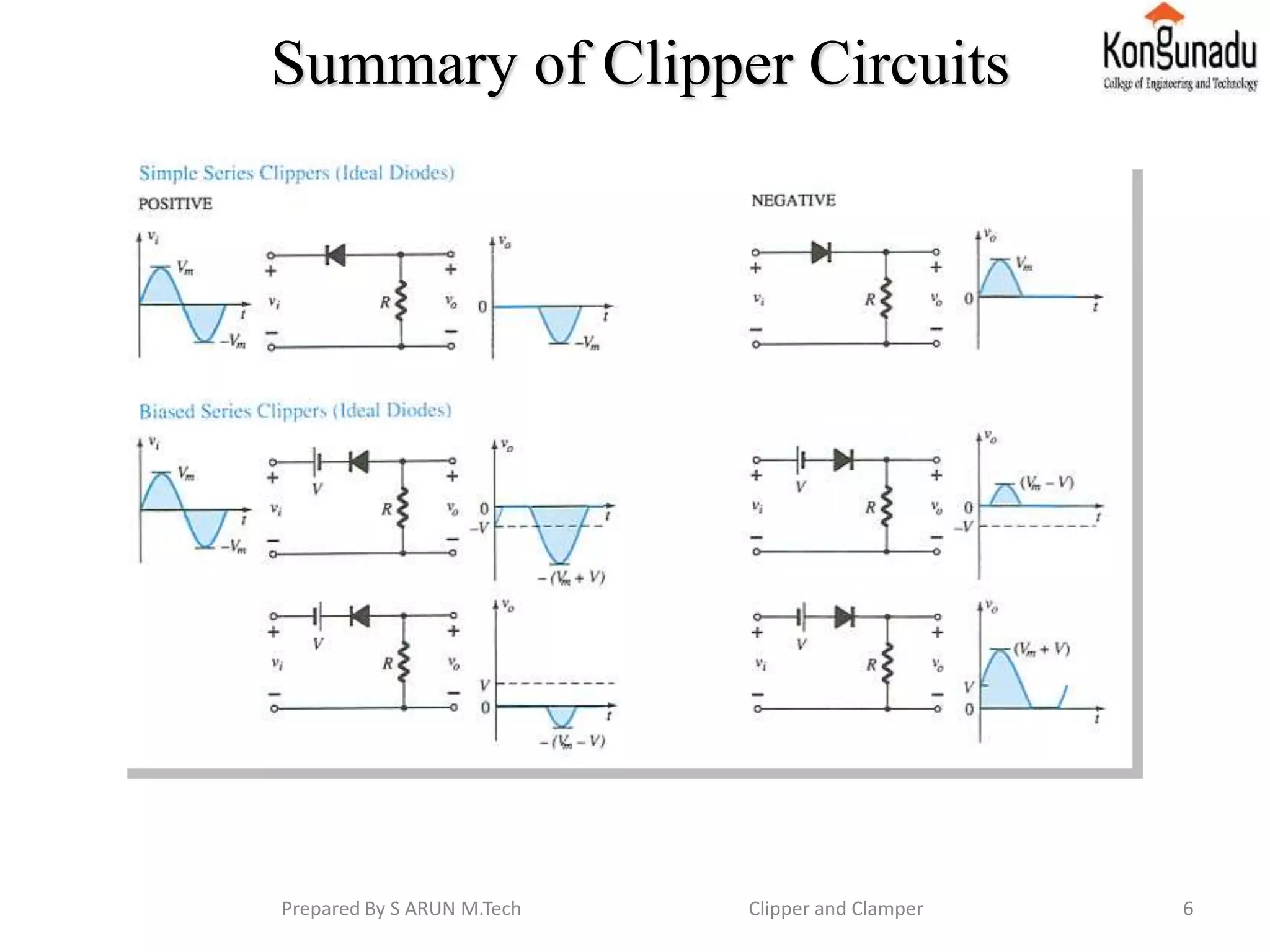
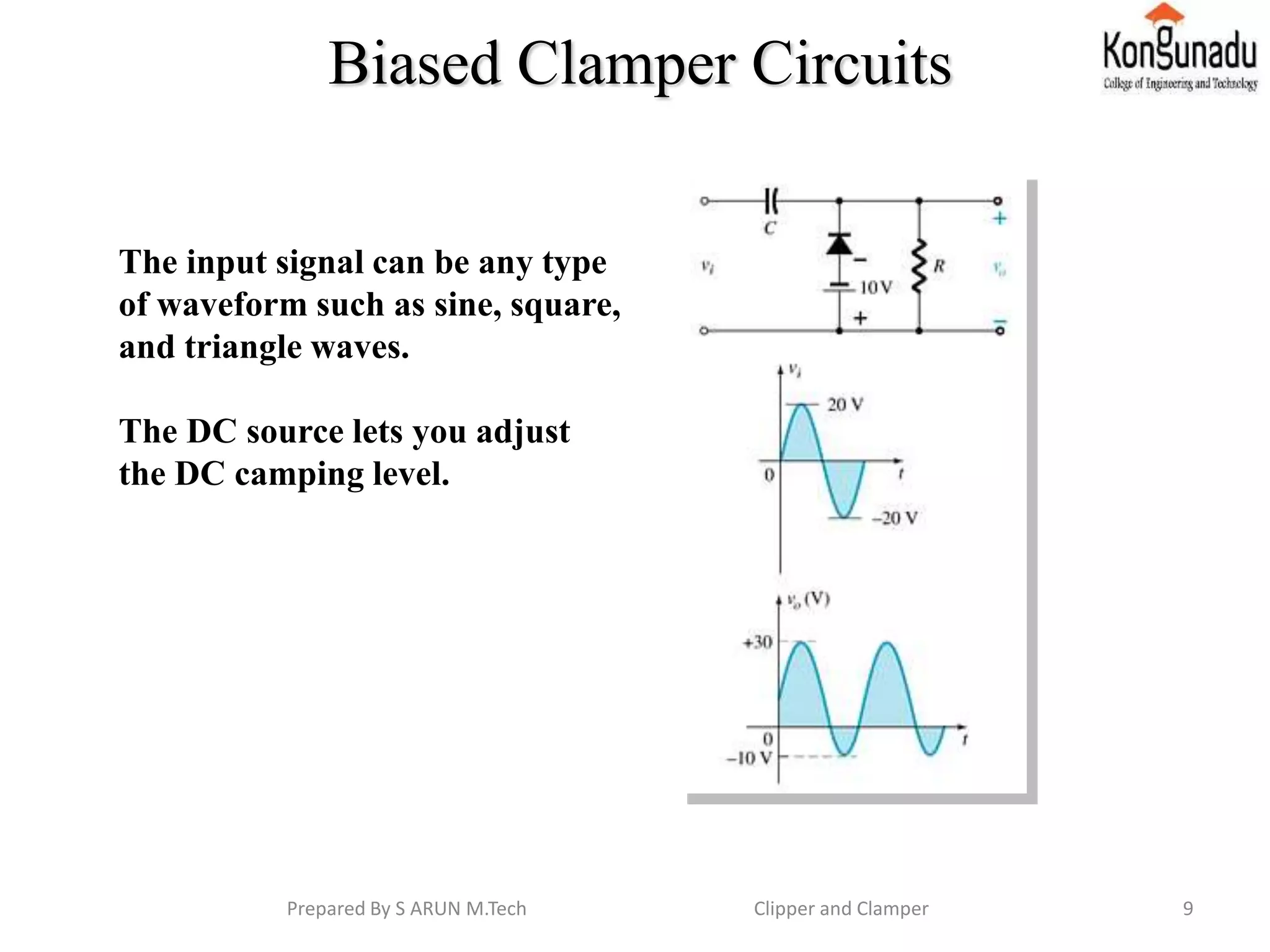
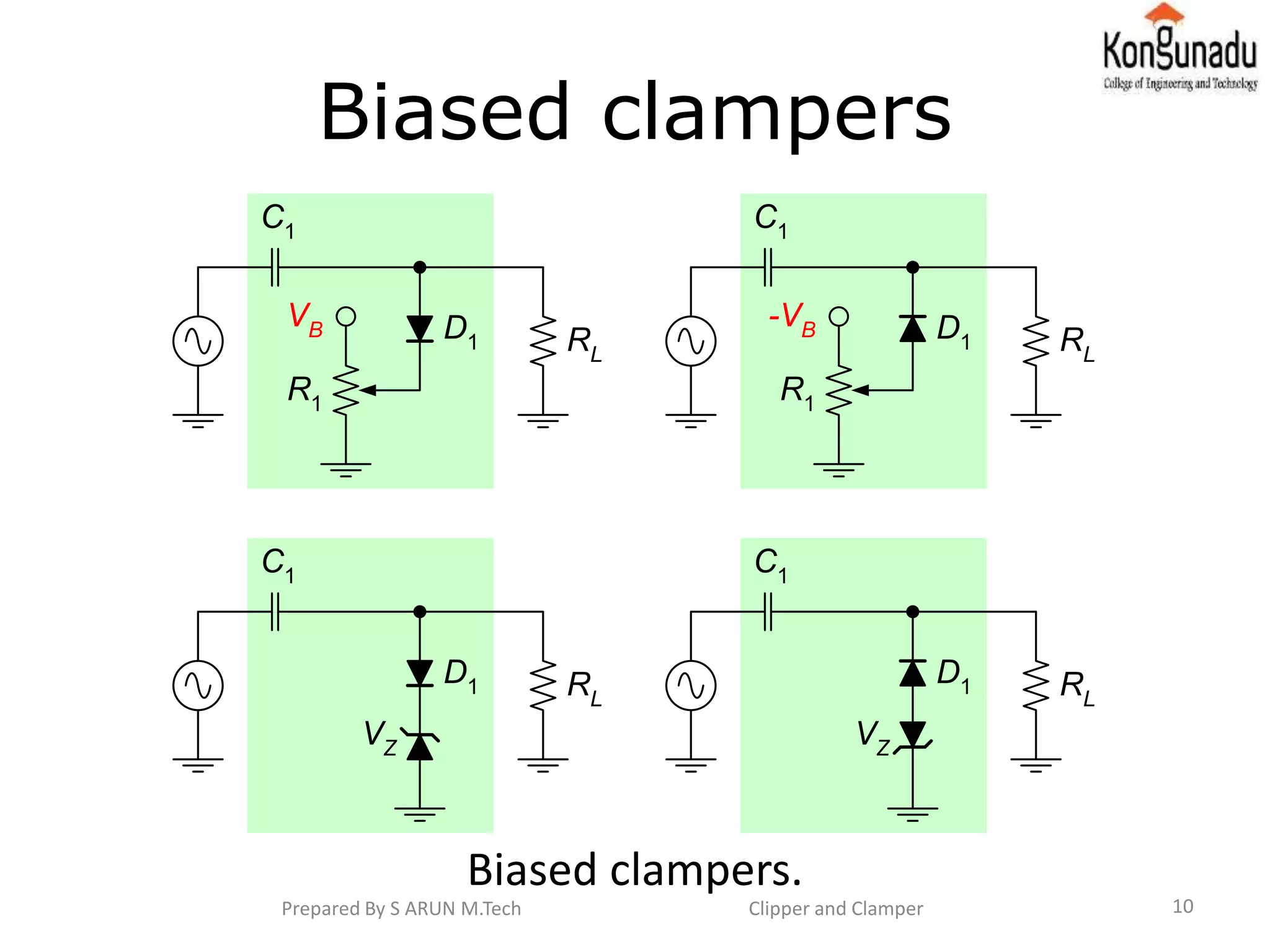
CLIPPER AND CLAMPER
Content
• Diode clipper
• Biased clipper
• Parallel clipper
• Summary of clipper circuit
• Clampers
• Clamper circuits
• Biased clamper circuits
• Conclusion and Reference
Prepared By S ARUN M.Tech Clipper and Clamper 1
Diode Clippers
•
The diode in a series clipper “clips”
any voltage that does not forward
bias it:
•A reverse-biasing polarity
•A forward-biasing polarity less than
0.7 V (for a silicon diode)
2Prepared By S ARUN M.Tech Clipper and Clamper
Biased Clippers
Adding a DC source in
series with the clipping
diode changes the
effective forward bias of
the diode.
3Prepared By S ARUN M.Tech Clipper and Clamper
Parallel Clippers
The diode in a parallel clipper
circuit “clips” any voltage that
forward bias it.
DC biasing can be added in
series with the diode to change
the clipping level.
4Prepared By S ARUN M.Tech Clipper and Clamper
Summary of Clipper Circuits
more…
5Prepared By S ARUN M.Tech Clipper and Clamper
Summary of Clipper Circuits
6Prepared By S ARUN M.Tech Clipper and Clamper
7
Clampers (DC restorers)
Input signal
source
Positive
clamper
Load
0V 0V20Vpp
20Vpp
Input signal
source
Negative
clamper
Load
0V20Vpp 0V
20Vpp
Prepared By S ARUN M.Tech Clipper and Clamper
8
Clamper circuits.
C1
D1 RL
C1
D1 RL
Negative clamper Positive clamper
A diode and capacitor can be
combined to “clamp” an AC
signal to a specific DC level.
Prepared By S ARUN M.Tech Clipper and Clamper
Biased Clamper Circuits
The input signal can be any type
of waveform such as sine, square,
and triangle waves.
The DC source lets you adjust
the DC camping level.
9Prepared By S ARUN M.Tech Clipper and Clamper
10
Biased clampers
Biased clampers.
VZ
C1
D1 RL
C1
RL
VZ
D1
VB
C1
D1
R1
RL
-VB
C1
D1
R1
RL
Prepared By S ARUN M.Tech Clipper and Clamper
• Conclusion
From these we came to know how to slicing
the given signal and clamping the signal.
• Reference
 Thomas L.Floyd, “Electronic devices”
Conventional current version, Pearson prentice
hall.
 David A. Bell, “Electronic devices and circuits”,
Oxford University higher education.
Prepared By S ARUN M.Tech Clipper and Clamper 11

Clipper and clamper

  • 1.
    CLIPPER AND CLAMPER Content •Diode clipper • Biased clipper • Parallel clipper • Summary of clipper circuit • Clampers • Clamper circuits • Biased clamper circuits • Conclusion and Reference Prepared By S ARUN M.Tech Clipper and Clamper 1
  • 2.
    Diode Clippers • The diodein a series clipper “clips” any voltage that does not forward bias it: •A reverse-biasing polarity •A forward-biasing polarity less than 0.7 V (for a silicon diode) 2Prepared By S ARUN M.Tech Clipper and Clamper
  • 3.
    Biased Clippers Adding aDC source in series with the clipping diode changes the effective forward bias of the diode. 3Prepared By S ARUN M.Tech Clipper and Clamper
  • 4.
    Parallel Clippers The diodein a parallel clipper circuit “clips” any voltage that forward bias it. DC biasing can be added in series with the diode to change the clipping level. 4Prepared By S ARUN M.Tech Clipper and Clamper
  • 5.
    Summary of ClipperCircuits more… 5Prepared By S ARUN M.Tech Clipper and Clamper
  • 6.
    Summary of ClipperCircuits 6Prepared By S ARUN M.Tech Clipper and Clamper
  • 7.
    7 Clampers (DC restorers) Inputsignal source Positive clamper Load 0V 0V20Vpp 20Vpp Input signal source Negative clamper Load 0V20Vpp 0V 20Vpp Prepared By S ARUN M.Tech Clipper and Clamper
  • 8.
    8 Clamper circuits. C1 D1 RL C1 D1RL Negative clamper Positive clamper A diode and capacitor can be combined to “clamp” an AC signal to a specific DC level. Prepared By S ARUN M.Tech Clipper and Clamper
  • 9.
    Biased Clamper Circuits Theinput signal can be any type of waveform such as sine, square, and triangle waves. The DC source lets you adjust the DC camping level. 9Prepared By S ARUN M.Tech Clipper and Clamper
  • 10.
    10 Biased clampers Biased clampers. VZ C1 D1RL C1 RL VZ D1 VB C1 D1 R1 RL -VB C1 D1 R1 RL Prepared By S ARUN M.Tech Clipper and Clamper
  • 11.
    • Conclusion From thesewe came to know how to slicing the given signal and clamping the signal. • Reference  Thomas L.Floyd, “Electronic devices” Conventional current version, Pearson prentice hall.  David A. Bell, “Electronic devices and circuits”, Oxford University higher education. Prepared By S ARUN M.Tech Clipper and Clamper 11