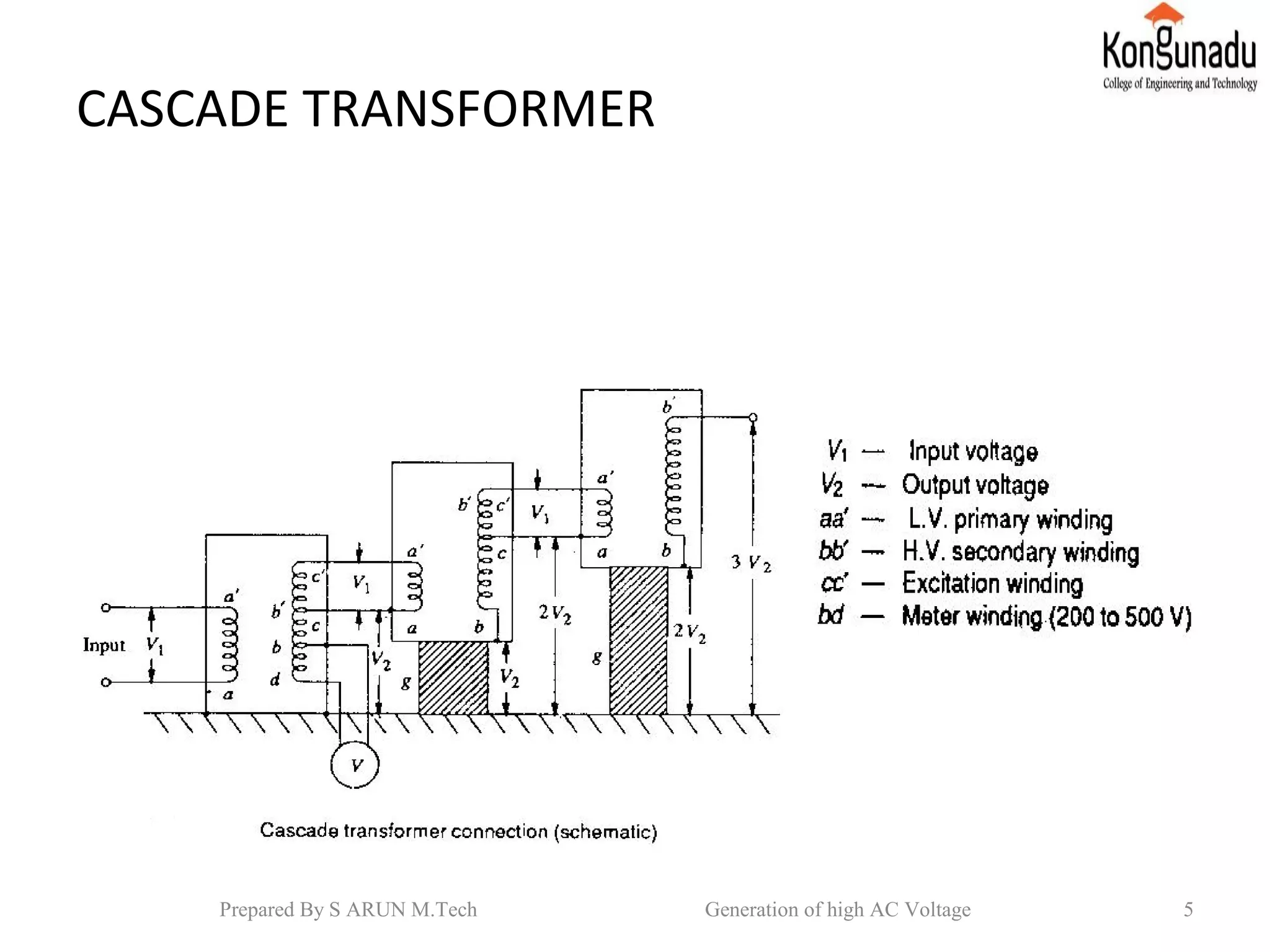
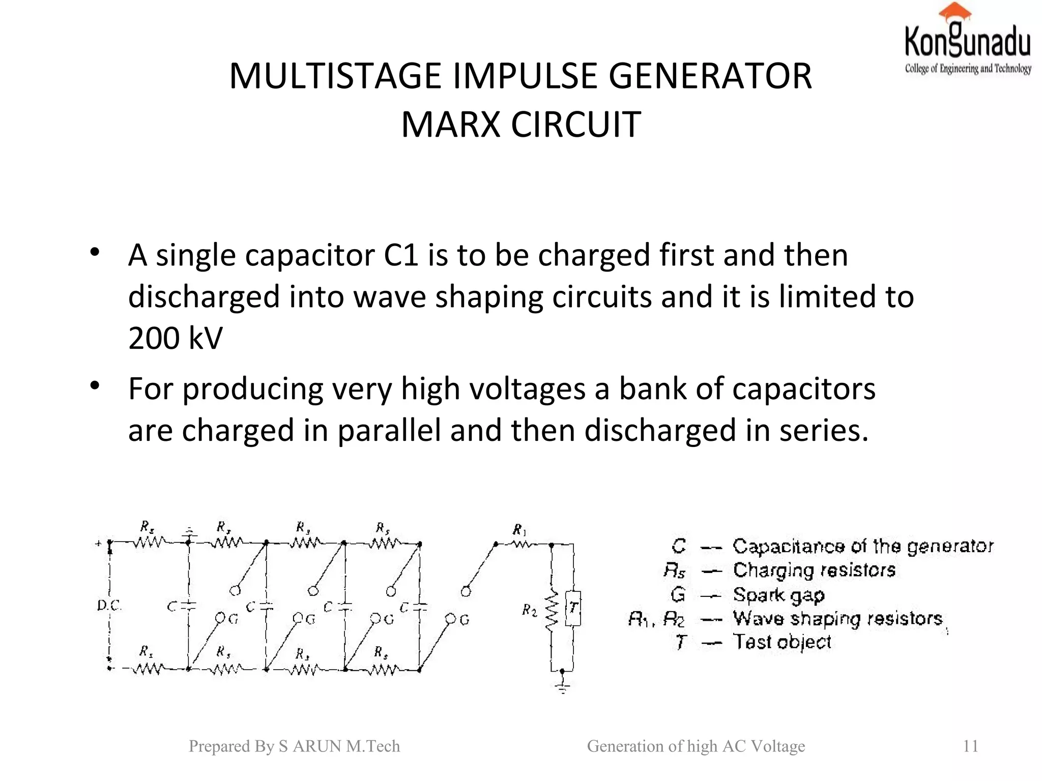
Generation of high AC voltages and
impulse voltages
Contents
•Introduction
•Cascade transformer
•Marx circuit
•Generation of switching surges
•Conclusion and Reference
Introduction
• When test voltage requirements are less than
about 300 kV,a single transformer can be used.
• Each transformer unit consists of low,high and
meter winding.
• Series connection of the several units of
transformers used to produce very high
voltage.
2Prepared By S ARUN M.Tech Generation of high AC Voltage
CASCADE TRANSFORMERS
• First transformer is at ground potential along with
its tank. The 2nd transformer is kept on insulators
and maintained at a potential of V2.
• The high voltage winding of the 1st unit is
connected to the tank of the 2nd unit, the low
voltage winging of this unit is supplied from the
excitation winding of the 1st transformer, which is
in series with the high voltage winding of the 1st
transformer at its high voltage end.
3Prepared By S ARUN M.Tech Generation of high AC Voltage
• The rating of the excitation winding is same as
that of low voltage winding.3rd
transformer is
kept on insulator above the ground at a
potential of 2V2.output of 3 stage is 3V2.
• The rating of the low voltage winding of 230
or 400 Vcan be used to produce 3.3 kV,6.6 kV
or 11 kV.
4Prepared By S ARUN M.Tech Generation of high AC Voltage
CASCADE TRANSFORMER
5Prepared By S ARUN M.Tech Generation of high AC Voltage
Cascade transformer with isolating transformer for
excitation
6Prepared By S ARUN M.Tech Generation of high AC Voltage
• High frequency high voltage damped oscillations are needed
which need high voltage high frequency transformer which is
a Tesla coil.
• Tesla coil is a doubly tuned resonant circuit, primary voltage
rating is 10 kV and secondary voltage rated from 500 to 1000
kV.
7Prepared By S ARUN M.Tech Generation of high AC Voltage
• The primary is fed from DC or AC supply through C1.A
spark gap G connected across the primary is triggered at V1
which induces a high self excitation in the secondary. The
windings are tuned to a frequency of 10 to 100 kHz.
STANDARD IMPULSE WAVESHAPE
• It is specified by rise or front time,fall or tail time to 50% peak
value and peak value.
• 1.2/50 μ s,1000 kV.
8Prepared By S ARUN M.Tech Generation of high AC Voltage
MARX CIRCUIT
• Charging resistance Rs is liming the charging
current from 50 to 100mA. CRs is about 10s to
1 min.
• The gap spacing G is grater than the charging
voltage V.All the capacitance s are charged to
the voltage V in 1 min.
• The spark gap G is made spark over, then all
the capacitor C get connected in series and
discharge into the load.
9Prepared By S ARUN M.Tech Generation of high AC Voltage
• In modified Marx circuit,R1is divided into n
parts equal to R1/n and put in series with the
gap G, R2is divided into n parts equal to R2/n
and connected across each capacitor unit after
the gap G.
• The nominal output is the number of stages
multiplied by the charging voltage.
10Prepared By S ARUN M.Tech Generation of high AC Voltage
MULTISTAGE IMPULSE GENERATOR
MARX CIRCUIT
• A single capacitor C1 is to be charged first and then
discharged into wave shaping circuits and it is limited to
200 kV
• For producing very high voltages a bank of capacitors
are charged in parallel and then discharged in series.
11Prepared By S ARUN M.Tech Generation of high AC Voltage
MULTI STAGE IMPULSE GENERATORS
Modified Marx Circuit
12Prepared By S ARUN M.Tech Generation of high AC Voltage
COMPONENTS OF A MULTISTAGE
IMPULSE GENERATOR
• DC Charging set
• Charging resistors
• Generator capacitors and spark gaps
• Wave shaping resistors and capacitors
• Triggering system
• Voltage dividers
13Prepared By S ARUN M.Tech Generation of high AC Voltage
GENERATION OF SWITCHING SURGES
• A switching surge is a short duration transient
voltage produced in the system due to a sudden
opening or closing of a switch or c.b or due to
an arcing at a fault in the system.
• Impulse generator circuit is modified to give
longer duration waveshape,100/1000 μs,R1 is
increased to very high value and it is parallel to
R2 in the discharge circuit.
14Prepared By S ARUN M.Tech Generation of high AC Voltage
• Power transformer excited by DC voltages giving
oscillatory waves which produces unidirectional
damped oscillations. Frequency of 1to 10 kHz
• Switching surges of very high peaks and long
duration can be obtained by one circuit, In this
circuit C1 charged to a low voltage d.c(20 to 25
kV) is discharged into the low voltage winding of
a power transformer. The high voltage winding is
connected in parallel to a load capacitance
C2,potential divider R2,gap S and test object.
15Prepared By S ARUN M.Tech Generation of high AC Voltage
• Conclusion
From these conclude that how to generate
high alternating voltages in power system
engineering.
• Reference
“High voltage engineering ” by M S Naidu and
V Kamaraju, Tata McGraw Hill Education, 5th
edition.
16Prepared By S ARUN M.Tech Generation of high AC Voltage

Ac impulse voltage

  • 1.
    Generation of highAC voltages and impulse voltages Contents •Introduction •Cascade transformer •Marx circuit •Generation of switching surges •Conclusion and Reference
  • 2.
    Introduction • When testvoltage requirements are less than about 300 kV,a single transformer can be used. • Each transformer unit consists of low,high and meter winding. • Series connection of the several units of transformers used to produce very high voltage. 2Prepared By S ARUN M.Tech Generation of high AC Voltage
  • 3.
    CASCADE TRANSFORMERS • Firsttransformer is at ground potential along with its tank. The 2nd transformer is kept on insulators and maintained at a potential of V2. • The high voltage winding of the 1st unit is connected to the tank of the 2nd unit, the low voltage winging of this unit is supplied from the excitation winding of the 1st transformer, which is in series with the high voltage winding of the 1st transformer at its high voltage end. 3Prepared By S ARUN M.Tech Generation of high AC Voltage
  • 4.
    • The ratingof the excitation winding is same as that of low voltage winding.3rd transformer is kept on insulator above the ground at a potential of 2V2.output of 3 stage is 3V2. • The rating of the low voltage winding of 230 or 400 Vcan be used to produce 3.3 kV,6.6 kV or 11 kV. 4Prepared By S ARUN M.Tech Generation of high AC Voltage
  • 5.
    CASCADE TRANSFORMER 5Prepared ByS ARUN M.Tech Generation of high AC Voltage
  • 6.
    Cascade transformer withisolating transformer for excitation 6Prepared By S ARUN M.Tech Generation of high AC Voltage
  • 7.
    • High frequencyhigh voltage damped oscillations are needed which need high voltage high frequency transformer which is a Tesla coil. • Tesla coil is a doubly tuned resonant circuit, primary voltage rating is 10 kV and secondary voltage rated from 500 to 1000 kV. 7Prepared By S ARUN M.Tech Generation of high AC Voltage
  • 8.
    • The primaryis fed from DC or AC supply through C1.A spark gap G connected across the primary is triggered at V1 which induces a high self excitation in the secondary. The windings are tuned to a frequency of 10 to 100 kHz. STANDARD IMPULSE WAVESHAPE • It is specified by rise or front time,fall or tail time to 50% peak value and peak value. • 1.2/50 μ s,1000 kV. 8Prepared By S ARUN M.Tech Generation of high AC Voltage
  • 9.
    MARX CIRCUIT • Chargingresistance Rs is liming the charging current from 50 to 100mA. CRs is about 10s to 1 min. • The gap spacing G is grater than the charging voltage V.All the capacitance s are charged to the voltage V in 1 min. • The spark gap G is made spark over, then all the capacitor C get connected in series and discharge into the load. 9Prepared By S ARUN M.Tech Generation of high AC Voltage
  • 10.
    • In modifiedMarx circuit,R1is divided into n parts equal to R1/n and put in series with the gap G, R2is divided into n parts equal to R2/n and connected across each capacitor unit after the gap G. • The nominal output is the number of stages multiplied by the charging voltage. 10Prepared By S ARUN M.Tech Generation of high AC Voltage
  • 11.
    MULTISTAGE IMPULSE GENERATOR MARXCIRCUIT • A single capacitor C1 is to be charged first and then discharged into wave shaping circuits and it is limited to 200 kV • For producing very high voltages a bank of capacitors are charged in parallel and then discharged in series. 11Prepared By S ARUN M.Tech Generation of high AC Voltage
  • 12.
    MULTI STAGE IMPULSEGENERATORS Modified Marx Circuit 12Prepared By S ARUN M.Tech Generation of high AC Voltage
  • 13.
    COMPONENTS OF AMULTISTAGE IMPULSE GENERATOR • DC Charging set • Charging resistors • Generator capacitors and spark gaps • Wave shaping resistors and capacitors • Triggering system • Voltage dividers 13Prepared By S ARUN M.Tech Generation of high AC Voltage
  • 14.
    GENERATION OF SWITCHINGSURGES • A switching surge is a short duration transient voltage produced in the system due to a sudden opening or closing of a switch or c.b or due to an arcing at a fault in the system. • Impulse generator circuit is modified to give longer duration waveshape,100/1000 μs,R1 is increased to very high value and it is parallel to R2 in the discharge circuit. 14Prepared By S ARUN M.Tech Generation of high AC Voltage
  • 15.
    • Power transformerexcited by DC voltages giving oscillatory waves which produces unidirectional damped oscillations. Frequency of 1to 10 kHz • Switching surges of very high peaks and long duration can be obtained by one circuit, In this circuit C1 charged to a low voltage d.c(20 to 25 kV) is discharged into the low voltage winding of a power transformer. The high voltage winding is connected in parallel to a load capacitance C2,potential divider R2,gap S and test object. 15Prepared By S ARUN M.Tech Generation of high AC Voltage
  • 16.
    • Conclusion From theseconclude that how to generate high alternating voltages in power system engineering. • Reference “High voltage engineering ” by M S Naidu and V Kamaraju, Tata McGraw Hill Education, 5th edition. 16Prepared By S ARUN M.Tech Generation of high AC Voltage