Downloaded 485 times

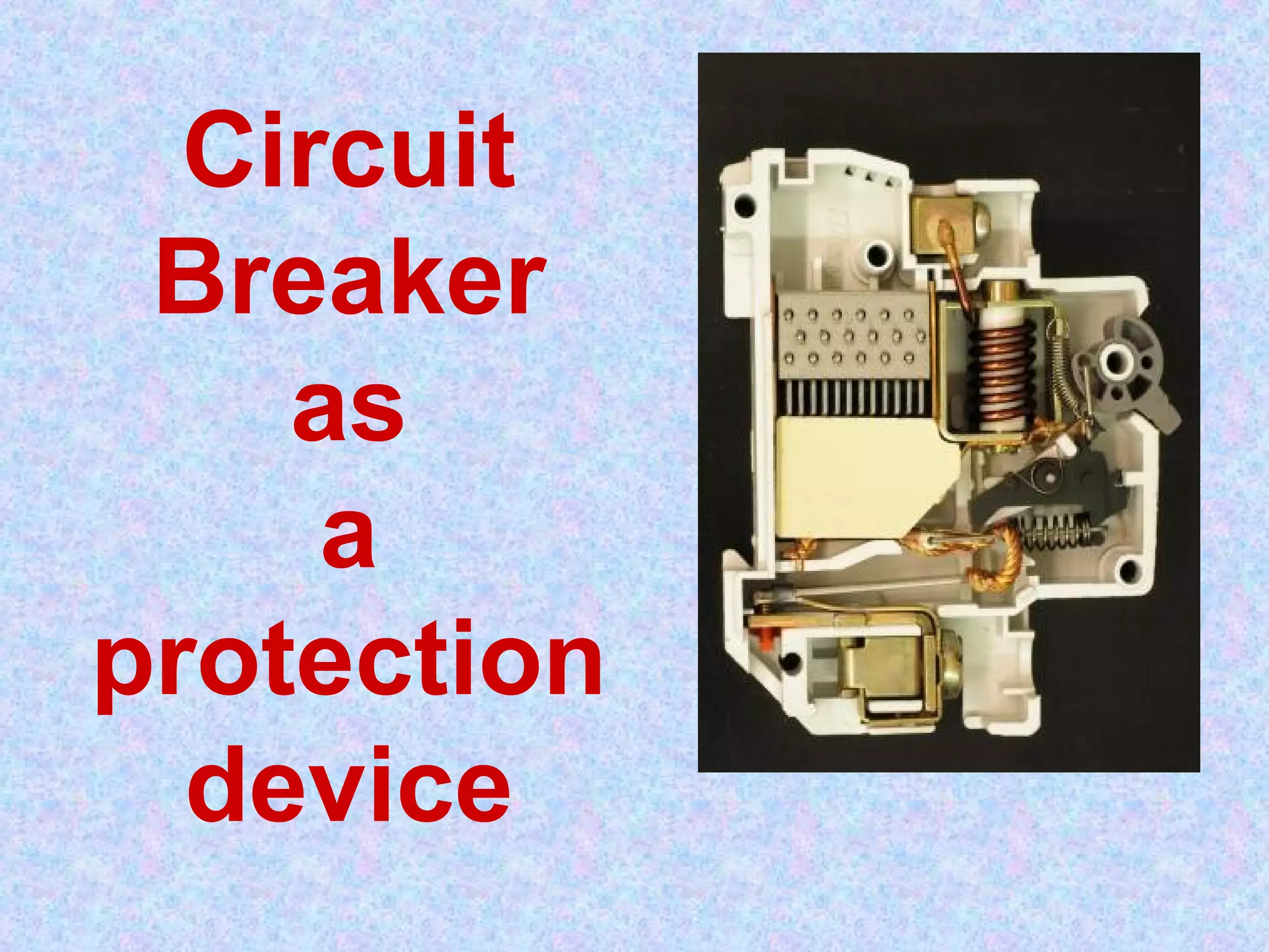
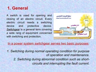
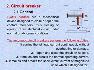
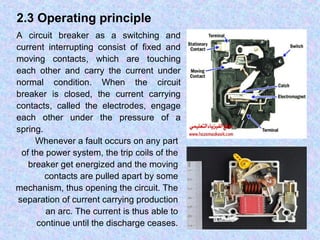


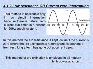
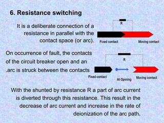
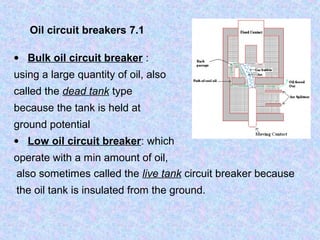
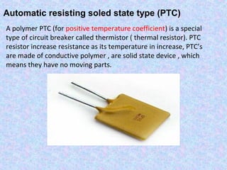
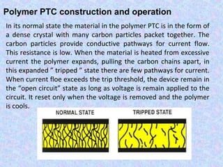

This document provides an overview of circuit breakers, including their operating principles, components, and classifications. Circuit breakers are mechanical switching devices that open and close electrical circuits under normal and abnormal conditions. They contain fixed and moving contacts to carry current when closed. When a fault occurs, the contacts separate, creating an arc that must be extinguished quickly. Circuit breakers use various insulating fluids or methods to cool the arc and reduce its conduction in order to interrupt the current. Common types include oil, air, sulfur hexafluoride, and vacuum circuit breakers.


![protection of transmission lines[distance relay protection scheme]](https://cdn.slidesharecdn.com/ss_thumbnails/os-exe3-23-may2011-sr-i-776s21tr-lineprotection-120425095503-phpapp02-thumbnail.jpg?width=640&height=640&fit=bounds)


