SlideShare a Scribd company logo
Work study
Unit-2
Work study
• Work study investigates the work done in an
organization and aims at finding the best and
the most efficient way of utilizing the available
resources (man, material, money and
machinery) to achieve best possible quality
work in minimum possible time.
Method Study
• Method Study is the systematic recording and critical
examination of existing and proposed ways of doing
work, as a means of developing and applying easier
and more effective methods and reducing costs.
• Can be used to
– the design of a new plant,
– the design of a new product,
– the design of a new process,
– the improvement of an existing process,
– the improvement of an existing workplace
Objectives of Method Study
1. Improvement of manufacturing processes and procedures.
2. Improvement of working conditions.
3. Improvement of plant layout and work place layout.
4. Reducing the human effort and fatigue.
5. Reducing material handling
6. Improvement of plant and equipment design.
7. Improvement in the utility of material, machines and manpower.
8. Standardization of method.
9. Improvement in safety standard.
Approach to Methods Design
Charles E. Geisel States that in order to design a system (method) thoroughly,
eight elements must be considered.
1. Purpose: The function, mission, aim or need for the system.
2. Input: The physical items, people, and/or information that enter the system to
be processed into the output.
3. Output: That which the system produces to accomplish its purpose, such as
finished steel, assembled toasters, boxes, and so forth.
4. Sequence: The steps required to convert, transform, or process the input to the
output.
5. Environment: The condition under which the system operates, including
physical, attitudinal, organizational, contractual, cultural, political, and legal
environment.
6. Human agents: The people who aid in the steps of the sequence without
becoming a part of the output.
7. Physical catalysts: The equipment and physical resources that aid in the steps of
the sequence without becoming part of the output.
8. Information aids: Knowledge and information resources that aid in the steps of
the sequence without becoming part of the output.
BASIC PROCEDURE FOR METHOD STUDY
1. Select the work to be studied.
2. Record all facts about the method by direct
observation.
3. Examine the above facts critically.
4. Develop the most efficient and economic
method.
5. Define the new method.
6. Install the new method
7. Maintain the new method by regular
checking.
Select
While selecting a job for doing method study, the following factors are considered:
Economical Factors
• The money saved as a result of method study should be sufficiently more. Then
only the study will be worthwhile.
• Based on the economical factors, generally the following jobs are selected.
– Operations having bottlenecks (which holds up other production activities).
– Operations done repetitively.
– Operations having a great amount of manual work.
– Operations where materials are moved for a long distance.
Human Factors
• The method study will be successful only with the co-operation of all people
concerned viz., workers, supervisor, trade unions etc. Workers may resist method
study due to
1. The fear of unemployment.
2. The fear of reduction in wages.
3. The fear of increased work load
Technical Factors
• To improve the method of work all the technical details about the job should be
available. Every machine tool will have its own capacity
Record
• All the details about the existing method are recorded. This is done by
directly observing the work. Symbols are used to represent the activities
like operation, inspection, transport, storage and delay. Different charts
and diagrams are used in recording.
• They are:
1. Operation process chart: All the operations and inspections are recorded.
2. Flow process chart
(a) Man type All the activities of man are recorded
(b) Material type All the activities of the material are recorded
(c) Equipment type All the activities of equipment or machine are recorded.
3. Two-handed process chart: Motions of both lands of worker are Right hand-Left hand
chart recorded independently.
4. Multiple activity chart: Activities of a group of workers doing a single job or the activities
of a single worker operating a number of machines are recorded.
5. Flow diagram: This is drawn to suitable scale. Path of flow of material in the shop is
recorded.
6. String diagram: The movements of workers are recorded using a string in a diagram drawn
to scale.
Examine
• Critical examination is done by questioning technique.
• This step comes after the method is recorded by suitable charts and
diagrams.
• The individual activity is examined by putting a number of questions.
• The following factors are questioned
1. Purpose – To eliminate the activity, if possible.
2. Place – To combine or re-arrange the activities.
3. Sequence – -do-
4. Person – -do-
5. Means – To simplify the activity.
Develop
• The answer to the questions given below will
result in the development of a better method.
1. Purpose – What should be done?
2. Place – Where should it be done?
3. Sequence – When should it be done?
4. Person – Who should do it?
5. Means – How should it be done?
DEFINE
• The report should show
(a) Brief description of the old method
(b) Brief description of the new method.
(c) Reasons for change.
(d) Advantages and limitations of the new method.
(e) Savings expected in material, labour and overheads.
(f) Tools and equipment required for the new method.
(g) The cost of installing the new method including.
1. Cost of new tools and equipment.
2. Cost of re-layout of the shop.
3. Cost of training the workers in the new method.
4. Cost of improving the working conditions.
Install
• This step is the most difficult stage in method study. Here the
active support of both management and trade union is
required.
• Here the work study man requires skill in getting along with
other people and winning their trust
• Install stage consists of
(a) Gaining acceptance of the change by supervisor.
(b) Getting approval of management.
(c) Gaining the acceptance of change by workers and trade unions.
(d) Giving training to operators in the new method.
(e) To be in close contact with the progress of the job until it is
satisfactorily executed.
Maintain
• The work study man must see that the new method
introduced is followed.
• The workers after some time may slip back to the old
methods. This should not be allowed.
• The new method may have defects. There may be difficulties
also. This should be rectified in time by the work study man.
• Periodical review is made. The reactions and suggestions from
workers and supervisors are noted. This may lead to further
improvement.
• The differences between the new written standard practice
and the actual practice are found out.
• Reasons for variations are analysed. Changes due to valid
reasons are accepted.
Process chart
• A process chart is setting out the sequence of
flow of a product or a procedure by recording
all events under review using appropriate
process chart-symbols.
• This chart gives a record of all events
associated with the worker.
– Operation,
– inspection,
– movement and
– delay
Application-Process charts
• Generally used as a principal means of recording work methods
• Helps to understand the overall nature of the system being studied
• Helps to eliminate flow patterns that are not suitable
• Helps to allow storage space adequate to support the production rate
• Helps to eliminate costly errors by analyzing the material flow
• Helps to allow adequate space to avoid safety problems
• Helps to locate and size aisles appropriate for product handled
• Helps to avoid backtracking of the material
• Helps to identify the possibility of combining operations by grouping
different machines or operations to avoid handling, storage, and delays
• Helps to decide whether product flow or process flow layout of factory will
be useful
CHARTS FOR PROCESS
1. Outline process charts
2. Flow process chart: man type, material type, equipment type
3. Two handed process chart
4. Multiple activity chart: using time scale
5. Simo chart: using time scale
6. Flow diagrams
7. String diagrams
8. Cyclograph
9. Chronocyclegraph
10. Travel Chart
METHOD STUDY CHARTS AND DIAGRAMS
• Charts indicating process
sequence
- Outline process chart
- Flow process chart – Man,
Material and Equipment
type
- Two-handed process chart
• Charts using a time scale
- Multiple activity chart
- Simo chart
- PMTS chart
• Diagrams indicating movement
- Flow diagram - Chronocyclegraph
- Sting diagram - Travel chart
- Cyclograph
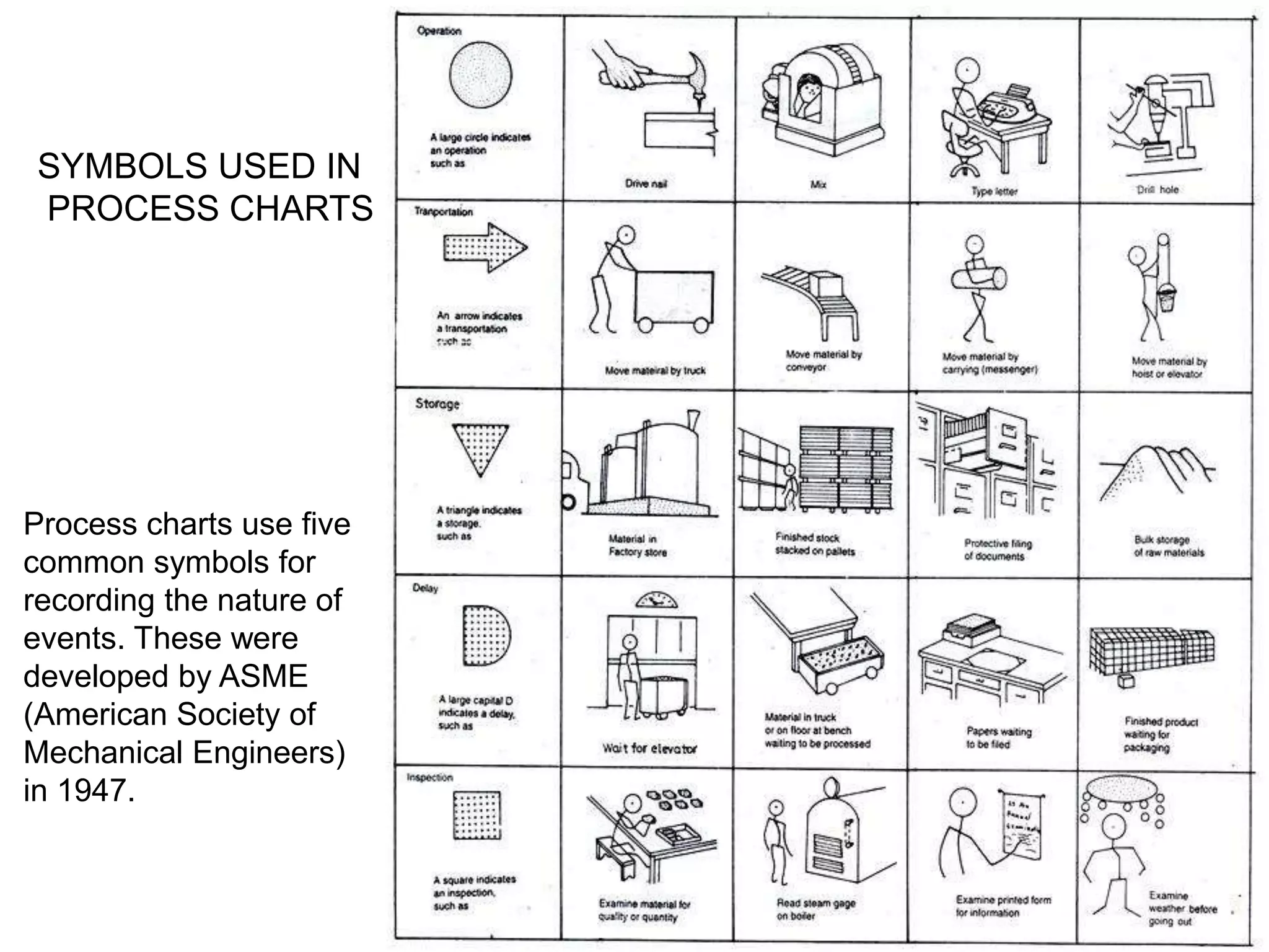
Process charts use five
common symbols for
recording the nature of
events. These were
developed by ASME
(American Society of
Mechanical Engineers)
in 1947.
SYMBOLS USED IN
PROCESS CHARTS
Operation Process Chart
• An operation process
chart is a graphic
representation of the
sequence of all
operations and
inspections taking place
in a process.
• It is also known as
outline process chart.
• It gives a bird‘s eye view
of the overall activities.
• Entry points of all
material are noted in the
chart.
• The fig. shows operation
process chart of a motor
assembly unit
Flow Process Chart
There are three types of
flow process charts.
They are
1. Man type flow
process chart
This flow process chart
records what the worker
does.
2. Material type flow
process chart
This flow process chart
records how the
material is handled or
treated.
3. Equipment type
flow process chart
This flow process chart
records how the
equipment or machine
is used.
Flow chart-Operator type
Two-Handed Process Chart (or)
Right Hand, Left Hand Chart
• It is the process chart in which the activities
of two hands of the operator are recorded.
• It shows whether the two hands of the
operator are idle or moving in relation to one
another, in a timescale.
• It is generally used for repetitive operations.
TWO HANDED PROCESS CHARTS
Multiple Activity Chart
• In those operations involving the combination of
– a person and a machine,
– a person and several machines,
– any combination of people and machines
• The multiple activity chart provides a convenient technique
for analyzing the combined activity.
• Objectives of this type of analysis are
– to attain the maximum utilization of a machine,
– to attain the optimum person to machine relationship,
– to bring about the best balance of crew activity.
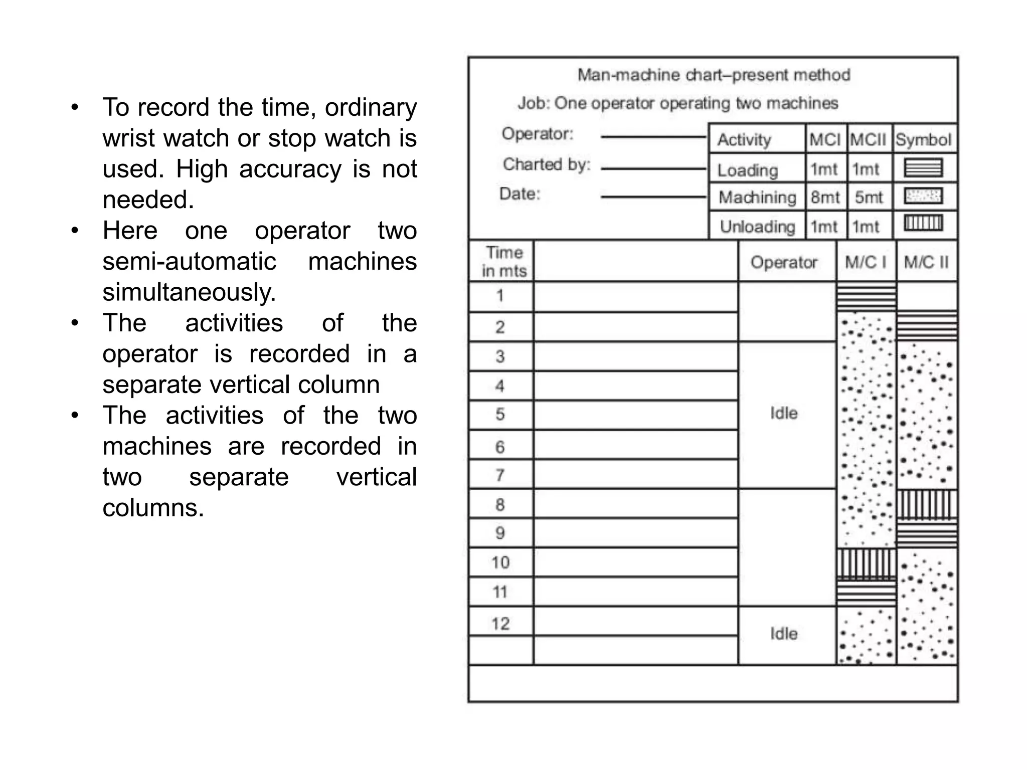
Man-Machine Chart
• A man-machine chart is a chart in which the activities of more
than one worker or machine are recorded.
• Activities are recorded on a common time scale to show the
inter-relationship. It is also known as multiple activity chart.
• It is used when a worker operates a number of machines at a
time.
• It is also used when a number of workers jointly do a job.
• Activities of workers or machines are recorded in separate
vertical columns (bars) with a horizontal time scale.
• The chart shows the idle time of the worker or machine
during the process.
• To record the time, ordinary
wrist watch or stop watch is
used. High accuracy is not
needed.
• Here one operator two
semi-automatic machines
simultaneously.
• The activities of the
operator is recorded in a
separate vertical column
• The activities of the two
machines are recorded in
two separate vertical
columns.
SIMO Charts
• A basic motion-time
chart used to show the
simultaneous nature of
motions;
• Commonly a therblig
chart for two-hand work
with motion symbols
plotted vertically with
respect to time,
showing the therblig
abbreviation and a brief
description for each
activity, and individual
times values and body-
member detail.
• Also known as
simultaneous motion-
cycle chart.
Therbligs
• Therbligs are 18 kinds of
elemental motions used
in the study of motion
economy in the
workplace.
• A workplace task is
analyzed by recording
each of the therblig units
for a process, with the
results used for
optimization of manual
labor by eliminating
unneeded movements.
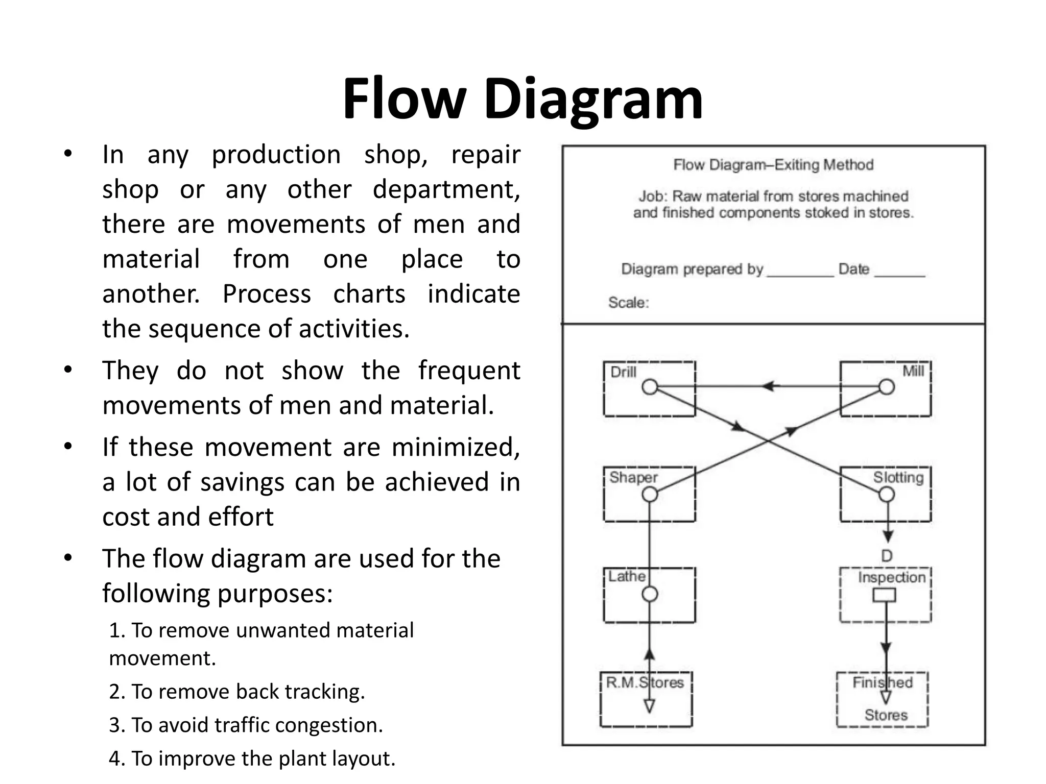
Flow Diagram
• In any production shop, repair
shop or any other department,
there are movements of men and
material from one place to
another. Process charts indicate
the sequence of activities.
• They do not show the frequent
movements of men and material.
• If these movement are minimized,
a lot of savings can be achieved in
cost and effort
• The flow diagram are used for the
following purposes:
1. To remove unwanted material
movement.
2. To remove back tracking.
3. To avoid traffic congestion.
4. To improve the plant layout.
String Diagram
• We make use of flow diagram
for recording the movement of
men or material when the
movement is simple and the
path is almost fixed.
• But when the paths are many
and are repetitive, it may not
be possible to record them in a
flow diagram. Here a string
diagram is used.
• String diagram is a scaled plan
of the shop.
• Location of machines and
various facilities are drawn to
scale in a drawing sheet.
Applications – String diagram
1. It is used for recording the complex
movements of material or men.
2. Back tracking, congestion, bottlenecks, under
utilized paths are easily found out.
3. It is used to check whether the work station is
correctly located.
4. Used to record irregular movements.
5. Used to find out the most economical route.
TRAVEL CHART ( or, FROM-TO CHART)
• It is a tabular record of quantitative data about movement
of workers/materials/equipment between any number of
places over a given period of time. It is always in the form
of a SQUIRE, having within it the squires.
EACH SMALL SQUIRE REPRESENTS A STATION.
Along the TOP, squires from left to right represent the
stations FROM where movement or travel occurs.
Along those DOWN THE LEFT HAND, the squires represent
the stations TO which the movement is made.
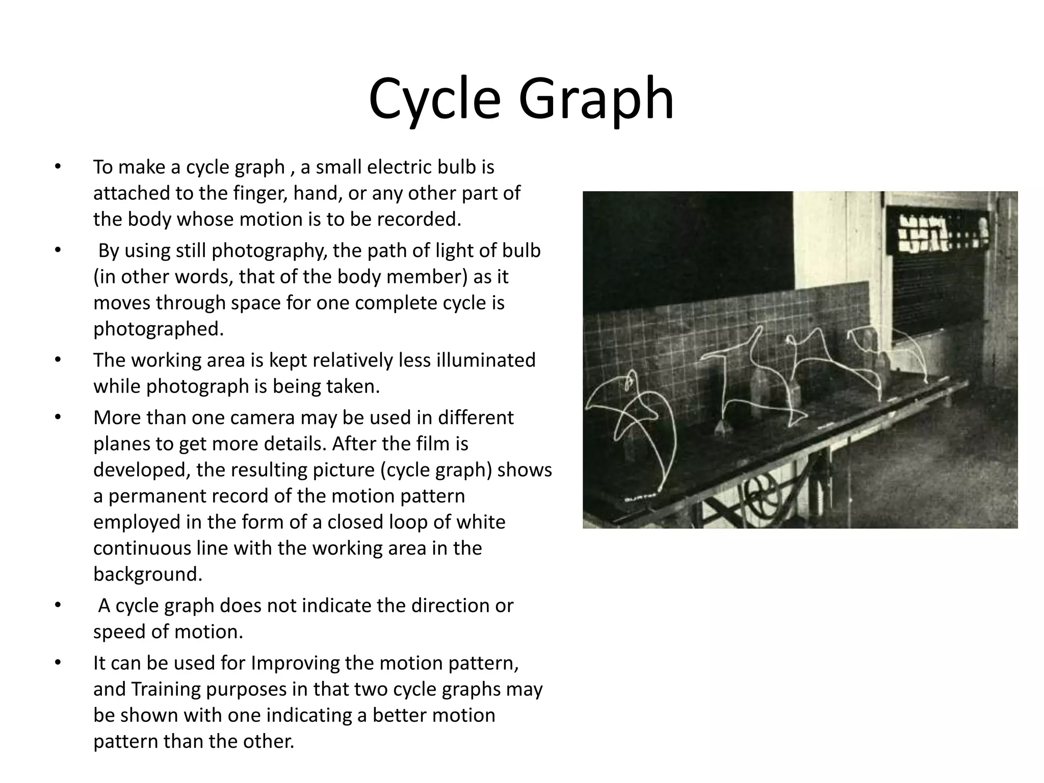
Cycle Graph
• To make a cycle graph , a small electric bulb is
attached to the finger, hand, or any other part of
the body whose motion is to be recorded.
• By using still photography, the path of light of bulb
(in other words, that of the body member) as it
moves through space for one complete cycle is
photographed.
• The working area is kept relatively less illuminated
while photograph is being taken.
• More than one camera may be used in different
planes to get more details. After the film is
developed, the resulting picture (cycle graph) shows
a permanent record of the motion pattern
employed in the form of a closed loop of white
continuous line with the working area in the
background.
• A cycle graph does not indicate the direction or
speed of motion.
• It can be used for Improving the motion pattern,
and Training purposes in that two cycle graphs may
be shown with one indicating a better motion
pattern than the other.
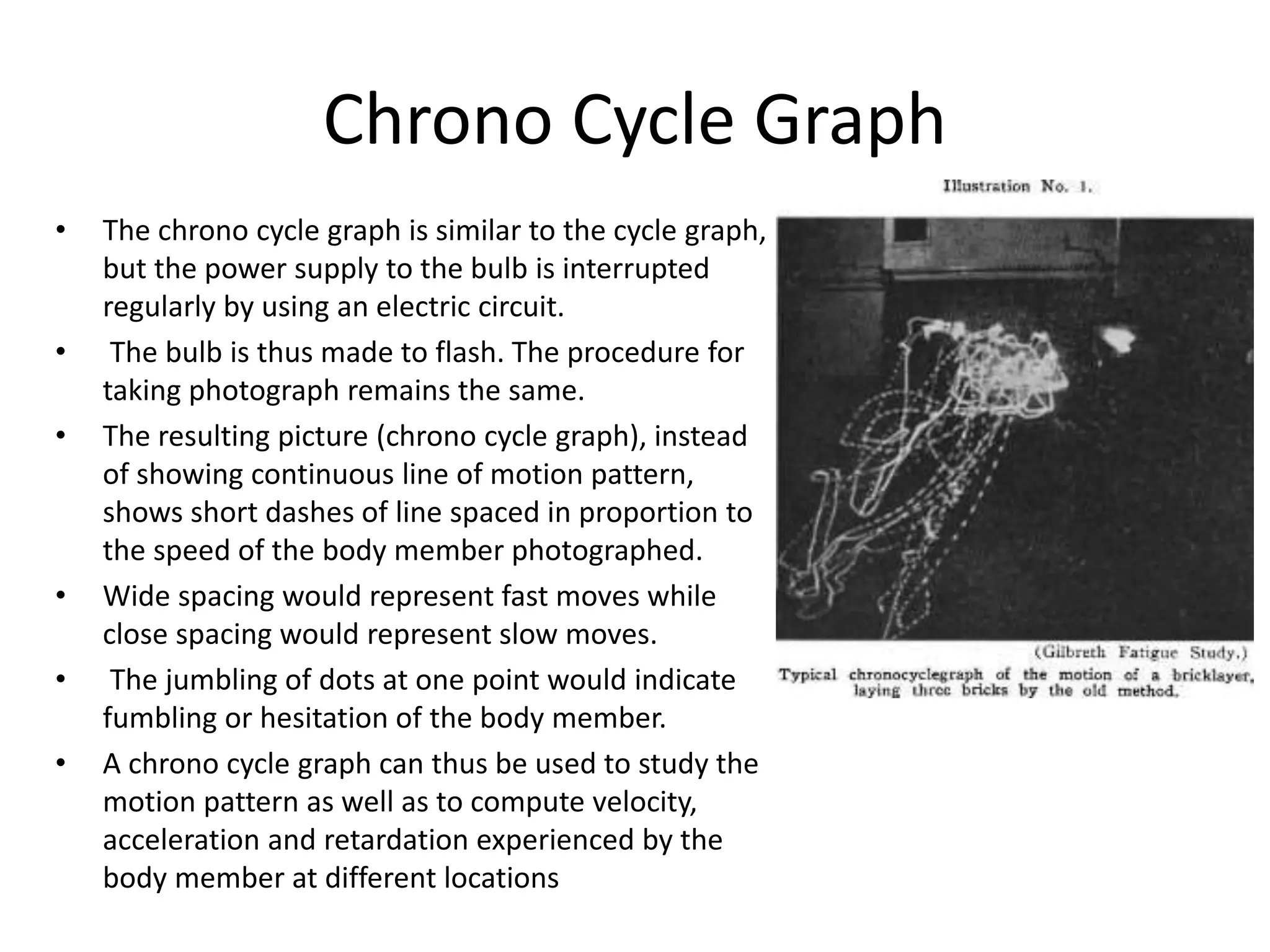
Chrono Cycle Graph
• The chrono cycle graph is similar to the cycle graph,
but the power supply to the bulb is interrupted
regularly by using an electric circuit.
• The bulb is thus made to flash. The procedure for
taking photograph remains the same.
• The resulting picture (chrono cycle graph), instead
of showing continuous line of motion pattern,
shows short dashes of line spaced in proportion to
the speed of the body member photographed.
• Wide spacing would represent fast moves while
close spacing would represent slow moves.
• The jumbling of dots at one point would indicate
fumbling or hesitation of the body member.
• A chrono cycle graph can thus be used to study the
motion pattern as well as to compute velocity,
acceleration and retardation experienced by the
body member at different locations
Principles of Motion Economy
• The principles of motion economy form a set
of rules and suggestions to improve the
manual work in manufacturing and reduce
fatigue and unnecessary movements by the
worker, which can lead to the reduction in the
work related trauma.
• The principles of motion economy can be
classified into three groups:
– Principles related to the use of human body,
– Principles related to the arrangement of the work
place,
– Principles related to the design of tools and
equipment.
Use of Human Body
• The two hands should begin motions at the same time.
• The two hands should not be idle at the same time except during rest periods.
• Motions of the arms should be made in opposite and symmetrical directions and
should be made simultaneously
• Hand motions should be confined to the lowest classification with which it is
possible to perform the work satisfactorily:
– Finger motions
– Wrist motions
– Forearm motions
– Upper arm motions
– Shoulder motions
• Momentum should be employed to assist the worker whenever possible, and it
should be reduced to a minimum if it must be overcome by muscular effort.
• Smooth continuous motions of the hands are preferable to zigzag motions or
straight-line motions involving sudden and sharp changes in direction.
Arrangement of the Work Place
• There should be a definite and fixed place for all tools and
materials.
• Tools, materials, and controls should be located close in and
directly in front of the operator.
• Drop delivers should be used whenever possible.
• Materials and tools should be located to permit the best
sequence of motions.
• Arrange the height of the workplace and chair for alternate
sitting and standing, when possible.
• Provide a chair of the type and height to permit good posture.
Design of Tools and Equipment
• Combine tools whenever possible.
• Preposition tools and materials.
• Where each finger performs some specific
movement, the load should be distributed in
accordance with the inherent capacities of the
fingers.
• For light assembly, a screwdriver handle should be
smaller at the bottom.
• Momentum should be used to help the worker in
doing their task not to increase their task.
MICROMOTION STUDY
• It is a technique for recording and timing
an activity.
• It consists of taking motion pictures of
the operation with a clock in the picture
(or with a video camera running at a
known speed.
• The film is a permanent record of the
method and the time and is always ready
to be examined when needed.
Purposes of Micromotion Study
1. To assist in finding the preferred method
of doing the work.
2. To assist in training the workers to
understand the meaning of motion study
and to enable them to apply motion
economy principles in a professional
way.
Micromotion study as an Aid in
Improving Methods
The procedure of making a micromotion study
consists of:
1. Filming the operation to be studied.
2. Analysing the film.
3. Charting the results of the analysis.
4. Developing the improved method.
Micromotion study
• The speed of the camera used ranges from 960 to 1000
frames per minute. But faster cameras may be used to study
very fast hand motions or complex operations.
• The pictures should be enlarged many times to facilitate the
analysis of the motions.
• Micromotion study should be used when it is economical to
do so (short cycle highly repetitive operations, large volume
production, or operation performed by a large number of
workers).
Memomotion Study
• In memomotion study, the camera speed is at
60 or 100 frames per minute.
• In addition to its use in industrial operations,
it is used to study many other operations such
as check-in operations as airline counters, the
manner in which customers select items in the
store, traffic flow on highways, and in banks.
• It costs less than micromotion study (only
costs 6% of the cost of a micromotion study
CRITICAL EXAMINATION
• Means by which each activity is subjected to a systematic and
progressive series of questions.
• Grouping of activities: Five sets of activities can be grouped in
two categories
• Those in which something actually happens to the work-piece
(it is moved, worked upon or examined)
• Those in which it is not being touched (in storage or in delay)
• Objective is to maximize proportion of “do” activities.
• All other activities, however necessary, are considered “non-
productive.”
DEVELOPMENT
• The shortcomings of the present process are brought out by
the systematic questioning process that is combined with a
knowledge relevant to the process being examined.
• Industrial may have the knowledge required or may not have
the adequate knowledge.
• They need to have a knowledge library to support their effort
as well as access to the experts during the study period.
• Alternatives to the current activities which have the
shortcomings are to be generated during this stage.
IMPLEMENTATION
• Industrial engineers of methods study persons
have to train the operators and their
supervisors in the new method and
participate in installing the method.
• Industrial engineers have to conduct a
periodic review of methods to observe
modifications brought into the installed
methods by operators and supervisors and if
they are beneficial, they have to be made part
of standard operating procedure (SOP).
Work measurement
• Work measurement is the application of
techniques designed to establish the time for
an average worker to carry out a
specified manufacturing task at a defined level
of performance.
• It is concerned with the length of time it takes
to complete a work task assigned to a specific
job.
Time study
• Time study is a direct and continuous observation of
a task, using a timekeeping device (e.g., decimal
minute stopwatch, computer-assisted electronic
stopwatch, and videotape camera) to record the time
taken to accomplish a task and it is often used when
– there are repetitive work cycles of short to long duration,
– wide variety of dissimilar work is performed, or
– process control elements constitute a part of the cycle.
Work sampling
There are several recommended steps when starting to prepare a work sampling
study:
• Define the manufacturing tasks for which the standard time is to be determined.
• Define the task elements. These are the defined broken-down steps of the task
that will be observed during the study. Since a worker is going to be observed,
additional categories will likely be included as well, such as "idle", "waiting for
work", and "absent".
• Design the study. This includes designing the forms that will be used to record the
observations, determining how many observations will be required, deciding on
the number of days or shifts to be included in the study, scheduling the
observations, and finally determining the number of observers needed.
• Identify the observers who will do the sampling.
• Start the study. All those who are affected by the study should be informed about
it.
• Make random visits to the plant and collect the observations.
• After completing the study, analyze and present the results. This is done by
preparing a report that summarizes and analyzes all data and making
recommendations when required.
PREDETERMINED MOTION TIME SYSTEM
• A predetermined motion time system (PMTS) is frequently
used to set labor rates in industry by quantifying the amount
of time required to perform specific tasks.
• The first such system is known as Methods-time
measurement, released in 1948 and today existing in several
variations, commonly known as MTM-1, MTM-2, MTM-UAS,
MTM-MEK and MTM-B.
• Obsolete MTM standards include MTM-3 and MMMM (4M).
The MTM-2 standard has also largely been phased out by the
organization, but is still used in some commercial applications.

More Related Content

What's hot

Ppc unit-2-work study
Ppc   unit-2-work studyPpc   unit-2-work study
Ppc unit-2-work study
karthi keyan
 
Ppc unit-4-production scheduling
Ppc   unit-4-production schedulingPpc   unit-4-production scheduling
Ppc unit-4-production scheduling
karthi keyan
 
PRODUCTION PLANNING AND CONTROL-Unit 3
PRODUCTION PLANNING AND CONTROL-Unit 3PRODUCTION PLANNING AND CONTROL-Unit 3
PRODUCTION PLANNING AND CONTROL-Unit 3
prakash0712
 
Work Study
Work Study Work Study
Work Study
PraveenManickam2
 
Ppc unit-1-production planning and control
Ppc   unit-1-production planning and controlPpc   unit-1-production planning and control
Ppc unit-1-production planning and control
karthi keyan
 
Unit 1 PPC
Unit 1 PPCUnit 1 PPC
Unit 1 PPC
Aravind Ra
 
Inventory production and Recent trends in PPC
Inventory production and Recent trends in PPCInventory production and Recent trends in PPC
Inventory production and Recent trends in PPC
PraveenManickam2
 
Production Planning and Process Planning
Production Planning and Process PlanningProduction Planning and Process Planning
Production Planning and Process Planning
PraveenManickam2
 
Unit 3
Unit 3Unit 3
Unit 3
Aravind Ra
 
Unit 1 cim
Unit 1 cimUnit 1 cim
Unit 1 cim
dinesh babu
 
Scheduling and sequencing
Scheduling and sequencingScheduling and sequencing
Scheduling and sequencingAkanksha Gupta
 
Unit 5
Unit 5Unit 5
Unit 5
Aravind Ra
 
Computer integrated production planning
Computer integrated production planningComputer integrated production planning
Computer integrated production planning
Venu Yadav
 
Unit 4-IE6605 & PRODUCTION PLANNING AND CONTROL
Unit 4-IE6605 & PRODUCTION PLANNING AND CONTROLUnit 4-IE6605 & PRODUCTION PLANNING AND CONTROL
Unit 4-IE6605 & PRODUCTION PLANNING AND CONTROL
Mohanumar S
 
COMPUTER AIDED PROCESS PLANNING
COMPUTER AIDED PROCESS PLANNINGCOMPUTER AIDED PROCESS PLANNING
COMPUTER AIDED PROCESS PLANNING
jntuhcej
 

What's hot (16)

Ppc unit-2-work study
Ppc   unit-2-work studyPpc   unit-2-work study
Ppc unit-2-work study
 
Ppc unit-4-production scheduling
Ppc   unit-4-production schedulingPpc   unit-4-production scheduling
Ppc unit-4-production scheduling
 
PRODUCTION PLANNING AND CONTROL-Unit 3
PRODUCTION PLANNING AND CONTROL-Unit 3PRODUCTION PLANNING AND CONTROL-Unit 3
PRODUCTION PLANNING AND CONTROL-Unit 3
 
Work Study
Work Study Work Study
Work Study
 
Ppc unit-1-production planning and control
Ppc   unit-1-production planning and controlPpc   unit-1-production planning and control
Ppc unit-1-production planning and control
 
Unit 1 PPC
Unit 1 PPCUnit 1 PPC
Unit 1 PPC
 
Inventory production and Recent trends in PPC
Inventory production and Recent trends in PPCInventory production and Recent trends in PPC
Inventory production and Recent trends in PPC
 
Production Planning and Process Planning
Production Planning and Process PlanningProduction Planning and Process Planning
Production Planning and Process Planning
 
Unit 3
Unit 3Unit 3
Unit 3
 
Unit 1 cim
Unit 1 cimUnit 1 cim
Unit 1 cim
 
Scheduling and sequencing
Scheduling and sequencingScheduling and sequencing
Scheduling and sequencing
 
Unit 5
Unit 5Unit 5
Unit 5
 
Computer integrated production planning
Computer integrated production planningComputer integrated production planning
Computer integrated production planning
 
Unit 4-IE6605 & PRODUCTION PLANNING AND CONTROL
Unit 4-IE6605 & PRODUCTION PLANNING AND CONTROLUnit 4-IE6605 & PRODUCTION PLANNING AND CONTROL
Unit 4-IE6605 & PRODUCTION PLANNING AND CONTROL
 
COMPUTER AIDED PROCESS PLANNING
COMPUTER AIDED PROCESS PLANNINGCOMPUTER AIDED PROCESS PLANNING
COMPUTER AIDED PROCESS PLANNING
 
Unit 2 manufacturing system design
Unit   2 manufacturing system designUnit   2 manufacturing system design
Unit 2 manufacturing system design
 

Similar to Unit 2

UNIT 2 - WORK STUDY
UNIT 2 -  WORK STUDYUNIT 2 -  WORK STUDY
Method study
Method studyMethod study
Method study
Ratnadeepsinh Jadeja
 
Work study IEM unit v for MEs2
Work study   IEM unit v  for MEs2Work study   IEM unit v  for MEs2
Work study IEM unit v for MEs2
kishorereddy_btech
 
Method study(abhishekkumar)
Method study(abhishekkumar)Method study(abhishekkumar)
Method study(abhishekkumar)Abhishek Kumar
 
Work study
Work studyWork study
Management tools
Management toolsManagement tools
Management tools
Paritosh Kasaudhan
 
Operations ManagementServices
Operations ManagementServicesOperations ManagementServices
Operations ManagementServices
ahmad bassiouny
 
PRODUCTION PLANNING AND CONTROL-WORK STUDY
PRODUCTION  PLANNING AND CONTROL-WORK STUDYPRODUCTION  PLANNING AND CONTROL-WORK STUDY
PRODUCTION PLANNING AND CONTROL-WORK STUDY
AttiMurugan
 
Work methods
Work methodsWork methods
Work methods
Shrikunj Patel
 
Facility Layout/Production Planning & Control(PPC)/ Method Study/ Capacity Pl...
Facility Layout/Production Planning & Control(PPC)/ Method Study/ Capacity Pl...Facility Layout/Production Planning & Control(PPC)/ Method Study/ Capacity Pl...
Facility Layout/Production Planning & Control(PPC)/ Method Study/ Capacity Pl...
viveksangwan007
 
OM2_Lecture 2.evdcgyhhgvkzfjfdhgxxfbggjdc
OM2_Lecture 2.evdcgyhhgvkzfjfdhgxxfbggjdcOM2_Lecture 2.evdcgyhhgvkzfjfdhgxxfbggjdc
OM2_Lecture 2.evdcgyhhgvkzfjfdhgxxfbggjdc
rammanoharjharunagar
 
Work study
Work studyWork study
Work study
Akshay Punde
 
Work study new
Work study newWork study new
Work study new
Chakravarti Chakri
 
Motion and time study
Motion and time studyMotion and time study
Motion and time study
Seta Wicaksana
 
Work Study- Methods Study
Work Study- Methods StudyWork Study- Methods Study
Work Study- Methods Study
Joseph Konnully
 
Lecture 1 work study as per Amravati University Syllabus
Lecture 1 work study as per Amravati University SyllabusLecture 1 work study as per Amravati University Syllabus
Lecture 1 work study as per Amravati University Syllabus
rahulmeshram14
 
1 work study as per amravati university syllabus
1 work study as per amravati university syllabus1 work study as per amravati university syllabus
1 work study as per amravati university syllabus
rahulmeshram14
 
Lecture 1 work study according to amravati university syllabus
Lecture 1 work study according to amravati university syllabus Lecture 1 work study according to amravati university syllabus
Lecture 1 work study according to amravati university syllabus rahulmeshram14
 

Similar to Unit 2 (20)

UNIT 2 - WORK STUDY
UNIT 2 -  WORK STUDYUNIT 2 -  WORK STUDY
UNIT 2 - WORK STUDY
 
PPC_UNIT - II.pptx
PPC_UNIT - II.pptxPPC_UNIT - II.pptx
PPC_UNIT - II.pptx
 
Method study
Method studyMethod study
Method study
 
Work study IEM unit v for MEs2
Work study   IEM unit v  for MEs2Work study   IEM unit v  for MEs2
Work study IEM unit v for MEs2
 
Method study(abhishekkumar)
Method study(abhishekkumar)Method study(abhishekkumar)
Method study(abhishekkumar)
 
Work study
Work studyWork study
Work study
 
Management tools
Management toolsManagement tools
Management tools
 
Operations ManagementServices
Operations ManagementServicesOperations ManagementServices
Operations ManagementServices
 
PRODUCTION PLANNING AND CONTROL-WORK STUDY
PRODUCTION  PLANNING AND CONTROL-WORK STUDYPRODUCTION  PLANNING AND CONTROL-WORK STUDY
PRODUCTION PLANNING AND CONTROL-WORK STUDY
 
Work methods
Work methodsWork methods
Work methods
 
Facility Layout/Production Planning & Control(PPC)/ Method Study/ Capacity Pl...
Facility Layout/Production Planning & Control(PPC)/ Method Study/ Capacity Pl...Facility Layout/Production Planning & Control(PPC)/ Method Study/ Capacity Pl...
Facility Layout/Production Planning & Control(PPC)/ Method Study/ Capacity Pl...
 
OM2_Lecture 2.evdcgyhhgvkzfjfdhgxxfbggjdc
OM2_Lecture 2.evdcgyhhgvkzfjfdhgxxfbggjdcOM2_Lecture 2.evdcgyhhgvkzfjfdhgxxfbggjdc
OM2_Lecture 2.evdcgyhhgvkzfjfdhgxxfbggjdc
 
Work study
Work studyWork study
Work study
 
Work study new
Work study newWork study new
Work study new
 
Motion and time study
Motion and time studyMotion and time study
Motion and time study
 
Work Study- Methods Study
Work Study- Methods StudyWork Study- Methods Study
Work Study- Methods Study
 
Lecture 1 work study as per Amravati University Syllabus
Lecture 1 work study as per Amravati University SyllabusLecture 1 work study as per Amravati University Syllabus
Lecture 1 work study as per Amravati University Syllabus
 
1 work study as per amravati university syllabus
1 work study as per amravati university syllabus1 work study as per amravati university syllabus
1 work study as per amravati university syllabus
 
Lecture 1 work study according to amravati university syllabus
Lecture 1 work study according to amravati university syllabus Lecture 1 work study according to amravati university syllabus
Lecture 1 work study according to amravati university syllabus
 
Work study
Work studyWork study
Work study
 

More from dinesh babu

Metrology Measurements and All units PPT
Metrology Measurements and  All units PPTMetrology Measurements and  All units PPT
Metrology Measurements and All units PPT
dinesh babu
 
Unit 5-CELLULAR MANUFACTURING AND FLEXIBLE MANUFACTURING SYSTEM (FMS) .pptx
Unit 5-CELLULAR MANUFACTURING AND FLEXIBLE MANUFACTURING SYSTEM (FMS) .pptxUnit 5-CELLULAR MANUFACTURING AND FLEXIBLE MANUFACTURING SYSTEM (FMS) .pptx
Unit 5-CELLULAR MANUFACTURING AND FLEXIBLE MANUFACTURING SYSTEM (FMS) .pptx
dinesh babu
 
Unit 4-FUNDAMENTAL OF CNC AND PART PROGRAMING.pptx
Unit 4-FUNDAMENTAL OF CNC AND PART PROGRAMING.pptxUnit 4-FUNDAMENTAL OF CNC AND PART PROGRAMING.pptx
Unit 4-FUNDAMENTAL OF CNC AND PART PROGRAMING.pptx
dinesh babu
 
Unit 3-ASSEMBLY OF PARTS AND CAD STANDARDS.pptx
Unit 3-ASSEMBLY OF PARTS AND CAD STANDARDS.pptxUnit 3-ASSEMBLY OF PARTS AND CAD STANDARDS.pptx
Unit 3-ASSEMBLY OF PARTS AND CAD STANDARDS.pptx
dinesh babu
 
UNIT 2-Geometric Modeling.pptx
UNIT 2-Geometric Modeling.pptxUNIT 2-Geometric Modeling.pptx
UNIT 2-Geometric Modeling.pptx
dinesh babu
 
UNIT 1-INTRODUCTION.pptx
UNIT 1-INTRODUCTION.pptxUNIT 1-INTRODUCTION.pptx
UNIT 1-INTRODUCTION.pptx
dinesh babu
 
UNIT-5FIRE SAFETY AND INSTALLATION.pptx
UNIT-5FIRE SAFETY AND INSTALLATION.pptxUNIT-5FIRE SAFETY AND INSTALLATION.pptx
UNIT-5FIRE SAFETY AND INSTALLATION.pptx
dinesh babu
 
UNIT-4-REFIGERATION PRINCIPLES.pptx
UNIT-4-REFIGERATION PRINCIPLES.pptxUNIT-4-REFIGERATION PRINCIPLES.pptx
UNIT-4-REFIGERATION PRINCIPLES.pptx
dinesh babu
 
UNIT-3-Principles of illumination.pptx
UNIT-3-Principles of illumination.pptxUNIT-3-Principles of illumination.pptx
UNIT-3-Principles of illumination.pptx
dinesh babu
 
UNIT-2-Electrical Systems.pptx
UNIT-2-Electrical Systems.pptxUNIT-2-Electrical Systems.pptx
UNIT-2-Electrical Systems.pptx
dinesh babu
 
UNIT-1-MACHINERIES.pptx
UNIT-1-MACHINERIES.pptxUNIT-1-MACHINERIES.pptx
UNIT-1-MACHINERIES.pptx
dinesh babu
 
UNIT- 2&3 based on gear life.pdf
UNIT- 2&3 based on gear life.pdfUNIT- 2&3 based on gear life.pdf
UNIT- 2&3 based on gear life.pdf
dinesh babu
 
ELEMENTS OF TECHNOLOGY.pdf
ELEMENTS OF TECHNOLOGY.pdfELEMENTS OF TECHNOLOGY.pdf
ELEMENTS OF TECHNOLOGY.pdf
dinesh babu
 
belt_drive.ppt
belt_drive.pptbelt_drive.ppt
belt_drive.ppt
dinesh babu
 
Unit iii
Unit iiiUnit iii
Unit iii
dinesh babu
 
Unit ii engine auxiliary systems
Unit ii engine auxiliary systemsUnit ii engine auxiliary systems
Unit ii engine auxiliary systems
dinesh babu
 
Unit i
Unit iUnit i
Unit i
dinesh babu
 
Unitv
Unitv   Unitv
Unitv
dinesh babu
 
Unit iv
Unit ivUnit iv
Unit iv
dinesh babu
 
Mm -unit iii
Mm -unit iii Mm -unit iii
Mm -unit iii
dinesh babu
 

More from dinesh babu (20)

Metrology Measurements and All units PPT
Metrology Measurements and  All units PPTMetrology Measurements and  All units PPT
Metrology Measurements and All units PPT
 
Unit 5-CELLULAR MANUFACTURING AND FLEXIBLE MANUFACTURING SYSTEM (FMS) .pptx
Unit 5-CELLULAR MANUFACTURING AND FLEXIBLE MANUFACTURING SYSTEM (FMS) .pptxUnit 5-CELLULAR MANUFACTURING AND FLEXIBLE MANUFACTURING SYSTEM (FMS) .pptx
Unit 5-CELLULAR MANUFACTURING AND FLEXIBLE MANUFACTURING SYSTEM (FMS) .pptx
 
Unit 4-FUNDAMENTAL OF CNC AND PART PROGRAMING.pptx
Unit 4-FUNDAMENTAL OF CNC AND PART PROGRAMING.pptxUnit 4-FUNDAMENTAL OF CNC AND PART PROGRAMING.pptx
Unit 4-FUNDAMENTAL OF CNC AND PART PROGRAMING.pptx
 
Unit 3-ASSEMBLY OF PARTS AND CAD STANDARDS.pptx
Unit 3-ASSEMBLY OF PARTS AND CAD STANDARDS.pptxUnit 3-ASSEMBLY OF PARTS AND CAD STANDARDS.pptx
Unit 3-ASSEMBLY OF PARTS AND CAD STANDARDS.pptx
 
UNIT 2-Geometric Modeling.pptx
UNIT 2-Geometric Modeling.pptxUNIT 2-Geometric Modeling.pptx
UNIT 2-Geometric Modeling.pptx
 
UNIT 1-INTRODUCTION.pptx
UNIT 1-INTRODUCTION.pptxUNIT 1-INTRODUCTION.pptx
UNIT 1-INTRODUCTION.pptx
 
UNIT-5FIRE SAFETY AND INSTALLATION.pptx
UNIT-5FIRE SAFETY AND INSTALLATION.pptxUNIT-5FIRE SAFETY AND INSTALLATION.pptx
UNIT-5FIRE SAFETY AND INSTALLATION.pptx
 
UNIT-4-REFIGERATION PRINCIPLES.pptx
UNIT-4-REFIGERATION PRINCIPLES.pptxUNIT-4-REFIGERATION PRINCIPLES.pptx
UNIT-4-REFIGERATION PRINCIPLES.pptx
 
UNIT-3-Principles of illumination.pptx
UNIT-3-Principles of illumination.pptxUNIT-3-Principles of illumination.pptx
UNIT-3-Principles of illumination.pptx
 
UNIT-2-Electrical Systems.pptx
UNIT-2-Electrical Systems.pptxUNIT-2-Electrical Systems.pptx
UNIT-2-Electrical Systems.pptx
 
UNIT-1-MACHINERIES.pptx
UNIT-1-MACHINERIES.pptxUNIT-1-MACHINERIES.pptx
UNIT-1-MACHINERIES.pptx
 
UNIT- 2&3 based on gear life.pdf
UNIT- 2&3 based on gear life.pdfUNIT- 2&3 based on gear life.pdf
UNIT- 2&3 based on gear life.pdf
 
ELEMENTS OF TECHNOLOGY.pdf
ELEMENTS OF TECHNOLOGY.pdfELEMENTS OF TECHNOLOGY.pdf
ELEMENTS OF TECHNOLOGY.pdf
 
belt_drive.ppt
belt_drive.pptbelt_drive.ppt
belt_drive.ppt
 
Unit iii
Unit iiiUnit iii
Unit iii
 
Unit ii engine auxiliary systems
Unit ii engine auxiliary systemsUnit ii engine auxiliary systems
Unit ii engine auxiliary systems
 
Unit i
Unit iUnit i
Unit i
 
Unitv
Unitv   Unitv
Unitv
 
Unit iv
Unit ivUnit iv
Unit iv
 
Mm -unit iii
Mm -unit iii Mm -unit iii
Mm -unit iii
 

Recently uploaded

Railway Signalling Principles Edition 3.pdf
Railway Signalling Principles Edition 3.pdfRailway Signalling Principles Edition 3.pdf
Railway Signalling Principles Edition 3.pdf
TeeVichai
 
DESIGN A COTTON SEED SEPARATION MACHINE.docx
DESIGN A COTTON SEED SEPARATION MACHINE.docxDESIGN A COTTON SEED SEPARATION MACHINE.docx
DESIGN A COTTON SEED SEPARATION MACHINE.docx
FluxPrime1
 
H.Seo, ICLR 2024, MLILAB, KAIST AI.pdf
H.Seo,  ICLR 2024, MLILAB,  KAIST AI.pdfH.Seo,  ICLR 2024, MLILAB,  KAIST AI.pdf
H.Seo, ICLR 2024, MLILAB, KAIST AI.pdf
MLILAB
 
The role of big data in decision making.
The role of big data in decision making.The role of big data in decision making.
The role of big data in decision making.
ankuprajapati0525
 
Immunizing Image Classifiers Against Localized Adversary Attacks
Immunizing Image Classifiers Against Localized Adversary AttacksImmunizing Image Classifiers Against Localized Adversary Attacks
Immunizing Image Classifiers Against Localized Adversary Attacks
gerogepatton
 
Design and Analysis of Algorithms-DP,Backtracking,Graphs,B&B
Design and Analysis of Algorithms-DP,Backtracking,Graphs,B&BDesign and Analysis of Algorithms-DP,Backtracking,Graphs,B&B
Design and Analysis of Algorithms-DP,Backtracking,Graphs,B&B
Sreedhar Chowdam
 
Sachpazis:Terzaghi Bearing Capacity Estimation in simple terms with Calculati...
Sachpazis:Terzaghi Bearing Capacity Estimation in simple terms with Calculati...Sachpazis:Terzaghi Bearing Capacity Estimation in simple terms with Calculati...
Sachpazis:Terzaghi Bearing Capacity Estimation in simple terms with Calculati...
Dr.Costas Sachpazis
 
CME397 Surface Engineering- Professional Elective
CME397 Surface Engineering- Professional ElectiveCME397 Surface Engineering- Professional Elective
CME397 Surface Engineering- Professional Elective
karthi keyan
 
MCQ Soil mechanics questions (Soil shear strength).pdf
MCQ Soil mechanics questions (Soil shear strength).pdfMCQ Soil mechanics questions (Soil shear strength).pdf
MCQ Soil mechanics questions (Soil shear strength).pdf
Osamah Alsalih
 
ethical hacking-mobile hacking methods.ppt
ethical hacking-mobile hacking methods.pptethical hacking-mobile hacking methods.ppt
ethical hacking-mobile hacking methods.ppt
Jayaprasanna4
 
Water Industry Process Automation and Control Monthly - May 2024.pdf
Water Industry Process Automation and Control Monthly - May 2024.pdfWater Industry Process Automation and Control Monthly - May 2024.pdf
Water Industry Process Automation and Control Monthly - May 2024.pdf
Water Industry Process Automation & Control
 
Fundamentals of Electric Drives and its applications.pptx
Fundamentals of Electric Drives and its applications.pptxFundamentals of Electric Drives and its applications.pptx
Fundamentals of Electric Drives and its applications.pptx
manasideore6
 
一比一原版(SFU毕业证)西蒙菲莎大学毕业证成绩单如何办理
一比一原版(SFU毕业证)西蒙菲莎大学毕业证成绩单如何办理一比一原版(SFU毕业证)西蒙菲莎大学毕业证成绩单如何办理
一比一原版(SFU毕业证)西蒙菲莎大学毕业证成绩单如何办理
bakpo1
 
Student information management system project report ii.pdf
Student information management system project report ii.pdfStudent information management system project report ii.pdf
Student information management system project report ii.pdf
Kamal Acharya
 
NO1 Uk best vashikaran specialist in delhi vashikaran baba near me online vas...
NO1 Uk best vashikaran specialist in delhi vashikaran baba near me online vas...NO1 Uk best vashikaran specialist in delhi vashikaran baba near me online vas...
NO1 Uk best vashikaran specialist in delhi vashikaran baba near me online vas...
Amil Baba Dawood bangali
 
space technology lecture notes on satellite
space technology lecture notes on satellitespace technology lecture notes on satellite
space technology lecture notes on satellite
ongomchris
 
ASME IX(9) 2007 Full Version .pdf
ASME IX(9)  2007 Full Version       .pdfASME IX(9)  2007 Full Version       .pdf
ASME IX(9) 2007 Full Version .pdf
AhmedHussein950959
 
在线办理(ANU毕业证书)澳洲国立大学毕业证录取通知书一模一样
在线办理(ANU毕业证书)澳洲国立大学毕业证录取通知书一模一样在线办理(ANU毕业证书)澳洲国立大学毕业证录取通知书一模一样
在线办理(ANU毕业证书)澳洲国立大学毕业证录取通知书一模一样
obonagu
 
一比一原版(UofT毕业证)多伦多大学毕业证成绩单如何办理
一比一原版(UofT毕业证)多伦多大学毕业证成绩单如何办理一比一原版(UofT毕业证)多伦多大学毕业证成绩单如何办理
一比一原版(UofT毕业证)多伦多大学毕业证成绩单如何办理
ydteq
 
RAT: Retrieval Augmented Thoughts Elicit Context-Aware Reasoning in Long-Hori...
RAT: Retrieval Augmented Thoughts Elicit Context-Aware Reasoning in Long-Hori...RAT: Retrieval Augmented Thoughts Elicit Context-Aware Reasoning in Long-Hori...
RAT: Retrieval Augmented Thoughts Elicit Context-Aware Reasoning in Long-Hori...
thanhdowork
 

Recently uploaded (20)

Railway Signalling Principles Edition 3.pdf
Railway Signalling Principles Edition 3.pdfRailway Signalling Principles Edition 3.pdf
Railway Signalling Principles Edition 3.pdf
 
DESIGN A COTTON SEED SEPARATION MACHINE.docx
DESIGN A COTTON SEED SEPARATION MACHINE.docxDESIGN A COTTON SEED SEPARATION MACHINE.docx
DESIGN A COTTON SEED SEPARATION MACHINE.docx
 
H.Seo, ICLR 2024, MLILAB, KAIST AI.pdf
H.Seo,  ICLR 2024, MLILAB,  KAIST AI.pdfH.Seo,  ICLR 2024, MLILAB,  KAIST AI.pdf
H.Seo, ICLR 2024, MLILAB, KAIST AI.pdf
 
The role of big data in decision making.
The role of big data in decision making.The role of big data in decision making.
The role of big data in decision making.
 
Immunizing Image Classifiers Against Localized Adversary Attacks
Immunizing Image Classifiers Against Localized Adversary AttacksImmunizing Image Classifiers Against Localized Adversary Attacks
Immunizing Image Classifiers Against Localized Adversary Attacks
 
Design and Analysis of Algorithms-DP,Backtracking,Graphs,B&B
Design and Analysis of Algorithms-DP,Backtracking,Graphs,B&BDesign and Analysis of Algorithms-DP,Backtracking,Graphs,B&B
Design and Analysis of Algorithms-DP,Backtracking,Graphs,B&B
 
Sachpazis:Terzaghi Bearing Capacity Estimation in simple terms with Calculati...
Sachpazis:Terzaghi Bearing Capacity Estimation in simple terms with Calculati...Sachpazis:Terzaghi Bearing Capacity Estimation in simple terms with Calculati...
Sachpazis:Terzaghi Bearing Capacity Estimation in simple terms with Calculati...
 
CME397 Surface Engineering- Professional Elective
CME397 Surface Engineering- Professional ElectiveCME397 Surface Engineering- Professional Elective
CME397 Surface Engineering- Professional Elective
 
MCQ Soil mechanics questions (Soil shear strength).pdf
MCQ Soil mechanics questions (Soil shear strength).pdfMCQ Soil mechanics questions (Soil shear strength).pdf
MCQ Soil mechanics questions (Soil shear strength).pdf
 
ethical hacking-mobile hacking methods.ppt
ethical hacking-mobile hacking methods.pptethical hacking-mobile hacking methods.ppt
ethical hacking-mobile hacking methods.ppt
 
Water Industry Process Automation and Control Monthly - May 2024.pdf
Water Industry Process Automation and Control Monthly - May 2024.pdfWater Industry Process Automation and Control Monthly - May 2024.pdf
Water Industry Process Automation and Control Monthly - May 2024.pdf
 
Fundamentals of Electric Drives and its applications.pptx
Fundamentals of Electric Drives and its applications.pptxFundamentals of Electric Drives and its applications.pptx
Fundamentals of Electric Drives and its applications.pptx
 
一比一原版(SFU毕业证)西蒙菲莎大学毕业证成绩单如何办理
一比一原版(SFU毕业证)西蒙菲莎大学毕业证成绩单如何办理一比一原版(SFU毕业证)西蒙菲莎大学毕业证成绩单如何办理
一比一原版(SFU毕业证)西蒙菲莎大学毕业证成绩单如何办理
 
Student information management system project report ii.pdf
Student information management system project report ii.pdfStudent information management system project report ii.pdf
Student information management system project report ii.pdf
 
NO1 Uk best vashikaran specialist in delhi vashikaran baba near me online vas...
NO1 Uk best vashikaran specialist in delhi vashikaran baba near me online vas...NO1 Uk best vashikaran specialist in delhi vashikaran baba near me online vas...
NO1 Uk best vashikaran specialist in delhi vashikaran baba near me online vas...
 
space technology lecture notes on satellite
space technology lecture notes on satellitespace technology lecture notes on satellite
space technology lecture notes on satellite
 
ASME IX(9) 2007 Full Version .pdf
ASME IX(9)  2007 Full Version       .pdfASME IX(9)  2007 Full Version       .pdf
ASME IX(9) 2007 Full Version .pdf
 
在线办理(ANU毕业证书)澳洲国立大学毕业证录取通知书一模一样
在线办理(ANU毕业证书)澳洲国立大学毕业证录取通知书一模一样在线办理(ANU毕业证书)澳洲国立大学毕业证录取通知书一模一样
在线办理(ANU毕业证书)澳洲国立大学毕业证录取通知书一模一样
 
一比一原版(UofT毕业证)多伦多大学毕业证成绩单如何办理
一比一原版(UofT毕业证)多伦多大学毕业证成绩单如何办理一比一原版(UofT毕业证)多伦多大学毕业证成绩单如何办理
一比一原版(UofT毕业证)多伦多大学毕业证成绩单如何办理
 
RAT: Retrieval Augmented Thoughts Elicit Context-Aware Reasoning in Long-Hori...
RAT: Retrieval Augmented Thoughts Elicit Context-Aware Reasoning in Long-Hori...RAT: Retrieval Augmented Thoughts Elicit Context-Aware Reasoning in Long-Hori...
RAT: Retrieval Augmented Thoughts Elicit Context-Aware Reasoning in Long-Hori...
 

Unit 2

  • 2. Work study • Work study investigates the work done in an organization and aims at finding the best and the most efficient way of utilizing the available resources (man, material, money and machinery) to achieve best possible quality work in minimum possible time.
  • 3. Method Study • Method Study is the systematic recording and critical examination of existing and proposed ways of doing work, as a means of developing and applying easier and more effective methods and reducing costs. • Can be used to – the design of a new plant, – the design of a new product, – the design of a new process, – the improvement of an existing process, – the improvement of an existing workplace
  • 4. Objectives of Method Study 1. Improvement of manufacturing processes and procedures. 2. Improvement of working conditions. 3. Improvement of plant layout and work place layout. 4. Reducing the human effort and fatigue. 5. Reducing material handling 6. Improvement of plant and equipment design. 7. Improvement in the utility of material, machines and manpower. 8. Standardization of method. 9. Improvement in safety standard.
  • 5. Approach to Methods Design Charles E. Geisel States that in order to design a system (method) thoroughly, eight elements must be considered. 1. Purpose: The function, mission, aim or need for the system. 2. Input: The physical items, people, and/or information that enter the system to be processed into the output. 3. Output: That which the system produces to accomplish its purpose, such as finished steel, assembled toasters, boxes, and so forth. 4. Sequence: The steps required to convert, transform, or process the input to the output. 5. Environment: The condition under which the system operates, including physical, attitudinal, organizational, contractual, cultural, political, and legal environment. 6. Human agents: The people who aid in the steps of the sequence without becoming a part of the output. 7. Physical catalysts: The equipment and physical resources that aid in the steps of the sequence without becoming part of the output. 8. Information aids: Knowledge and information resources that aid in the steps of the sequence without becoming part of the output.
  • 6. BASIC PROCEDURE FOR METHOD STUDY 1. Select the work to be studied. 2. Record all facts about the method by direct observation. 3. Examine the above facts critically. 4. Develop the most efficient and economic method. 5. Define the new method. 6. Install the new method 7. Maintain the new method by regular checking.
  • 7. Select While selecting a job for doing method study, the following factors are considered: Economical Factors • The money saved as a result of method study should be sufficiently more. Then only the study will be worthwhile. • Based on the economical factors, generally the following jobs are selected. – Operations having bottlenecks (which holds up other production activities). – Operations done repetitively. – Operations having a great amount of manual work. – Operations where materials are moved for a long distance. Human Factors • The method study will be successful only with the co-operation of all people concerned viz., workers, supervisor, trade unions etc. Workers may resist method study due to 1. The fear of unemployment. 2. The fear of reduction in wages. 3. The fear of increased work load Technical Factors • To improve the method of work all the technical details about the job should be available. Every machine tool will have its own capacity
  • 8. Record • All the details about the existing method are recorded. This is done by directly observing the work. Symbols are used to represent the activities like operation, inspection, transport, storage and delay. Different charts and diagrams are used in recording. • They are: 1. Operation process chart: All the operations and inspections are recorded. 2. Flow process chart (a) Man type All the activities of man are recorded (b) Material type All the activities of the material are recorded (c) Equipment type All the activities of equipment or machine are recorded. 3. Two-handed process chart: Motions of both lands of worker are Right hand-Left hand chart recorded independently. 4. Multiple activity chart: Activities of a group of workers doing a single job or the activities of a single worker operating a number of machines are recorded. 5. Flow diagram: This is drawn to suitable scale. Path of flow of material in the shop is recorded. 6. String diagram: The movements of workers are recorded using a string in a diagram drawn to scale.
  • 9. Examine • Critical examination is done by questioning technique. • This step comes after the method is recorded by suitable charts and diagrams. • The individual activity is examined by putting a number of questions. • The following factors are questioned 1. Purpose – To eliminate the activity, if possible. 2. Place – To combine or re-arrange the activities. 3. Sequence – -do- 4. Person – -do- 5. Means – To simplify the activity.
  • 10. Develop • The answer to the questions given below will result in the development of a better method. 1. Purpose – What should be done? 2. Place – Where should it be done? 3. Sequence – When should it be done? 4. Person – Who should do it? 5. Means – How should it be done?
  • 11. DEFINE • The report should show (a) Brief description of the old method (b) Brief description of the new method. (c) Reasons for change. (d) Advantages and limitations of the new method. (e) Savings expected in material, labour and overheads. (f) Tools and equipment required for the new method. (g) The cost of installing the new method including. 1. Cost of new tools and equipment. 2. Cost of re-layout of the shop. 3. Cost of training the workers in the new method. 4. Cost of improving the working conditions.
  • 12. Install • This step is the most difficult stage in method study. Here the active support of both management and trade union is required. • Here the work study man requires skill in getting along with other people and winning their trust • Install stage consists of (a) Gaining acceptance of the change by supervisor. (b) Getting approval of management. (c) Gaining the acceptance of change by workers and trade unions. (d) Giving training to operators in the new method. (e) To be in close contact with the progress of the job until it is satisfactorily executed.
  • 13. Maintain • The work study man must see that the new method introduced is followed. • The workers after some time may slip back to the old methods. This should not be allowed. • The new method may have defects. There may be difficulties also. This should be rectified in time by the work study man. • Periodical review is made. The reactions and suggestions from workers and supervisors are noted. This may lead to further improvement. • The differences between the new written standard practice and the actual practice are found out. • Reasons for variations are analysed. Changes due to valid reasons are accepted.
  • 14. Process chart • A process chart is setting out the sequence of flow of a product or a procedure by recording all events under review using appropriate process chart-symbols. • This chart gives a record of all events associated with the worker. – Operation, – inspection, – movement and – delay
  • 15. Application-Process charts • Generally used as a principal means of recording work methods • Helps to understand the overall nature of the system being studied • Helps to eliminate flow patterns that are not suitable • Helps to allow storage space adequate to support the production rate • Helps to eliminate costly errors by analyzing the material flow • Helps to allow adequate space to avoid safety problems • Helps to locate and size aisles appropriate for product handled • Helps to avoid backtracking of the material • Helps to identify the possibility of combining operations by grouping different machines or operations to avoid handling, storage, and delays • Helps to decide whether product flow or process flow layout of factory will be useful
  • 16. CHARTS FOR PROCESS 1. Outline process charts 2. Flow process chart: man type, material type, equipment type 3. Two handed process chart 4. Multiple activity chart: using time scale 5. Simo chart: using time scale 6. Flow diagrams 7. String diagrams 8. Cyclograph 9. Chronocyclegraph 10. Travel Chart
  • 17. METHOD STUDY CHARTS AND DIAGRAMS • Charts indicating process sequence - Outline process chart - Flow process chart – Man, Material and Equipment type - Two-handed process chart • Charts using a time scale - Multiple activity chart - Simo chart - PMTS chart • Diagrams indicating movement - Flow diagram - Chronocyclegraph - Sting diagram - Travel chart - Cyclograph
  • 18. Process charts use five common symbols for recording the nature of events. These were developed by ASME (American Society of Mechanical Engineers) in 1947. SYMBOLS USED IN PROCESS CHARTS
  • 19. Operation Process Chart • An operation process chart is a graphic representation of the sequence of all operations and inspections taking place in a process. • It is also known as outline process chart. • It gives a bird‘s eye view of the overall activities. • Entry points of all material are noted in the chart. • The fig. shows operation process chart of a motor assembly unit
  • 20. Flow Process Chart There are three types of flow process charts. They are 1. Man type flow process chart This flow process chart records what the worker does. 2. Material type flow process chart This flow process chart records how the material is handled or treated. 3. Equipment type flow process chart This flow process chart records how the equipment or machine is used.
  • 22. Two-Handed Process Chart (or) Right Hand, Left Hand Chart • It is the process chart in which the activities of two hands of the operator are recorded. • It shows whether the two hands of the operator are idle or moving in relation to one another, in a timescale. • It is generally used for repetitive operations.
  • 24. Multiple Activity Chart • In those operations involving the combination of – a person and a machine, – a person and several machines, – any combination of people and machines • The multiple activity chart provides a convenient technique for analyzing the combined activity. • Objectives of this type of analysis are – to attain the maximum utilization of a machine, – to attain the optimum person to machine relationship, – to bring about the best balance of crew activity.
  • 25. Man-Machine Chart • A man-machine chart is a chart in which the activities of more than one worker or machine are recorded. • Activities are recorded on a common time scale to show the inter-relationship. It is also known as multiple activity chart. • It is used when a worker operates a number of machines at a time. • It is also used when a number of workers jointly do a job. • Activities of workers or machines are recorded in separate vertical columns (bars) with a horizontal time scale. • The chart shows the idle time of the worker or machine during the process.
  • 26. • To record the time, ordinary wrist watch or stop watch is used. High accuracy is not needed. • Here one operator two semi-automatic machines simultaneously. • The activities of the operator is recorded in a separate vertical column • The activities of the two machines are recorded in two separate vertical columns.
  • 27. SIMO Charts • A basic motion-time chart used to show the simultaneous nature of motions; • Commonly a therblig chart for two-hand work with motion symbols plotted vertically with respect to time, showing the therblig abbreviation and a brief description for each activity, and individual times values and body- member detail. • Also known as simultaneous motion- cycle chart.
  • 28. Therbligs • Therbligs are 18 kinds of elemental motions used in the study of motion economy in the workplace. • A workplace task is analyzed by recording each of the therblig units for a process, with the results used for optimization of manual labor by eliminating unneeded movements.
  • 29. Flow Diagram • In any production shop, repair shop or any other department, there are movements of men and material from one place to another. Process charts indicate the sequence of activities. • They do not show the frequent movements of men and material. • If these movement are minimized, a lot of savings can be achieved in cost and effort • The flow diagram are used for the following purposes: 1. To remove unwanted material movement. 2. To remove back tracking. 3. To avoid traffic congestion. 4. To improve the plant layout.
  • 30. String Diagram • We make use of flow diagram for recording the movement of men or material when the movement is simple and the path is almost fixed. • But when the paths are many and are repetitive, it may not be possible to record them in a flow diagram. Here a string diagram is used. • String diagram is a scaled plan of the shop. • Location of machines and various facilities are drawn to scale in a drawing sheet.
  • 31. Applications – String diagram 1. It is used for recording the complex movements of material or men. 2. Back tracking, congestion, bottlenecks, under utilized paths are easily found out. 3. It is used to check whether the work station is correctly located. 4. Used to record irregular movements. 5. Used to find out the most economical route.
  • 32. TRAVEL CHART ( or, FROM-TO CHART) • It is a tabular record of quantitative data about movement of workers/materials/equipment between any number of places over a given period of time. It is always in the form of a SQUIRE, having within it the squires. EACH SMALL SQUIRE REPRESENTS A STATION. Along the TOP, squires from left to right represent the stations FROM where movement or travel occurs. Along those DOWN THE LEFT HAND, the squires represent the stations TO which the movement is made.
  • 33. Cycle Graph • To make a cycle graph , a small electric bulb is attached to the finger, hand, or any other part of the body whose motion is to be recorded. • By using still photography, the path of light of bulb (in other words, that of the body member) as it moves through space for one complete cycle is photographed. • The working area is kept relatively less illuminated while photograph is being taken. • More than one camera may be used in different planes to get more details. After the film is developed, the resulting picture (cycle graph) shows a permanent record of the motion pattern employed in the form of a closed loop of white continuous line with the working area in the background. • A cycle graph does not indicate the direction or speed of motion. • It can be used for Improving the motion pattern, and Training purposes in that two cycle graphs may be shown with one indicating a better motion pattern than the other.
  • 34. Chrono Cycle Graph • The chrono cycle graph is similar to the cycle graph, but the power supply to the bulb is interrupted regularly by using an electric circuit. • The bulb is thus made to flash. The procedure for taking photograph remains the same. • The resulting picture (chrono cycle graph), instead of showing continuous line of motion pattern, shows short dashes of line spaced in proportion to the speed of the body member photographed. • Wide spacing would represent fast moves while close spacing would represent slow moves. • The jumbling of dots at one point would indicate fumbling or hesitation of the body member. • A chrono cycle graph can thus be used to study the motion pattern as well as to compute velocity, acceleration and retardation experienced by the body member at different locations
  • 35. Principles of Motion Economy • The principles of motion economy form a set of rules and suggestions to improve the manual work in manufacturing and reduce fatigue and unnecessary movements by the worker, which can lead to the reduction in the work related trauma.
  • 36. • The principles of motion economy can be classified into three groups: – Principles related to the use of human body, – Principles related to the arrangement of the work place, – Principles related to the design of tools and equipment.
  • 37. Use of Human Body • The two hands should begin motions at the same time. • The two hands should not be idle at the same time except during rest periods. • Motions of the arms should be made in opposite and symmetrical directions and should be made simultaneously • Hand motions should be confined to the lowest classification with which it is possible to perform the work satisfactorily: – Finger motions – Wrist motions – Forearm motions – Upper arm motions – Shoulder motions • Momentum should be employed to assist the worker whenever possible, and it should be reduced to a minimum if it must be overcome by muscular effort. • Smooth continuous motions of the hands are preferable to zigzag motions or straight-line motions involving sudden and sharp changes in direction.
  • 38. Arrangement of the Work Place • There should be a definite and fixed place for all tools and materials. • Tools, materials, and controls should be located close in and directly in front of the operator. • Drop delivers should be used whenever possible. • Materials and tools should be located to permit the best sequence of motions. • Arrange the height of the workplace and chair for alternate sitting and standing, when possible. • Provide a chair of the type and height to permit good posture.
  • 39. Design of Tools and Equipment • Combine tools whenever possible. • Preposition tools and materials. • Where each finger performs some specific movement, the load should be distributed in accordance with the inherent capacities of the fingers. • For light assembly, a screwdriver handle should be smaller at the bottom. • Momentum should be used to help the worker in doing their task not to increase their task.
  • 40. MICROMOTION STUDY • It is a technique for recording and timing an activity. • It consists of taking motion pictures of the operation with a clock in the picture (or with a video camera running at a known speed. • The film is a permanent record of the method and the time and is always ready to be examined when needed.
  • 41. Purposes of Micromotion Study 1. To assist in finding the preferred method of doing the work. 2. To assist in training the workers to understand the meaning of motion study and to enable them to apply motion economy principles in a professional way.
  • 42. Micromotion study as an Aid in Improving Methods The procedure of making a micromotion study consists of: 1. Filming the operation to be studied. 2. Analysing the film. 3. Charting the results of the analysis. 4. Developing the improved method.
  • 43. Micromotion study • The speed of the camera used ranges from 960 to 1000 frames per minute. But faster cameras may be used to study very fast hand motions or complex operations. • The pictures should be enlarged many times to facilitate the analysis of the motions. • Micromotion study should be used when it is economical to do so (short cycle highly repetitive operations, large volume production, or operation performed by a large number of workers).
  • 44. Memomotion Study • In memomotion study, the camera speed is at 60 or 100 frames per minute. • In addition to its use in industrial operations, it is used to study many other operations such as check-in operations as airline counters, the manner in which customers select items in the store, traffic flow on highways, and in banks. • It costs less than micromotion study (only costs 6% of the cost of a micromotion study
  • 45. CRITICAL EXAMINATION • Means by which each activity is subjected to a systematic and progressive series of questions. • Grouping of activities: Five sets of activities can be grouped in two categories • Those in which something actually happens to the work-piece (it is moved, worked upon or examined) • Those in which it is not being touched (in storage or in delay) • Objective is to maximize proportion of “do” activities. • All other activities, however necessary, are considered “non- productive.”
  • 46. DEVELOPMENT • The shortcomings of the present process are brought out by the systematic questioning process that is combined with a knowledge relevant to the process being examined. • Industrial may have the knowledge required or may not have the adequate knowledge. • They need to have a knowledge library to support their effort as well as access to the experts during the study period. • Alternatives to the current activities which have the shortcomings are to be generated during this stage.
  • 47. IMPLEMENTATION • Industrial engineers of methods study persons have to train the operators and their supervisors in the new method and participate in installing the method. • Industrial engineers have to conduct a periodic review of methods to observe modifications brought into the installed methods by operators and supervisors and if they are beneficial, they have to be made part of standard operating procedure (SOP).
  • 48. Work measurement • Work measurement is the application of techniques designed to establish the time for an average worker to carry out a specified manufacturing task at a defined level of performance. • It is concerned with the length of time it takes to complete a work task assigned to a specific job.
  • 49. Time study • Time study is a direct and continuous observation of a task, using a timekeeping device (e.g., decimal minute stopwatch, computer-assisted electronic stopwatch, and videotape camera) to record the time taken to accomplish a task and it is often used when – there are repetitive work cycles of short to long duration, – wide variety of dissimilar work is performed, or – process control elements constitute a part of the cycle.
  • 50. Work sampling There are several recommended steps when starting to prepare a work sampling study: • Define the manufacturing tasks for which the standard time is to be determined. • Define the task elements. These are the defined broken-down steps of the task that will be observed during the study. Since a worker is going to be observed, additional categories will likely be included as well, such as "idle", "waiting for work", and "absent". • Design the study. This includes designing the forms that will be used to record the observations, determining how many observations will be required, deciding on the number of days or shifts to be included in the study, scheduling the observations, and finally determining the number of observers needed. • Identify the observers who will do the sampling. • Start the study. All those who are affected by the study should be informed about it. • Make random visits to the plant and collect the observations. • After completing the study, analyze and present the results. This is done by preparing a report that summarizes and analyzes all data and making recommendations when required.
  • 51. PREDETERMINED MOTION TIME SYSTEM • A predetermined motion time system (PMTS) is frequently used to set labor rates in industry by quantifying the amount of time required to perform specific tasks. • The first such system is known as Methods-time measurement, released in 1948 and today existing in several variations, commonly known as MTM-1, MTM-2, MTM-UAS, MTM-MEK and MTM-B. • Obsolete MTM standards include MTM-3 and MMMM (4M). The MTM-2 standard has also largely been phased out by the organization, but is still used in some commercial applications.