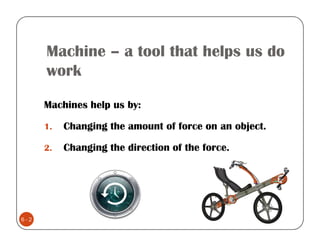
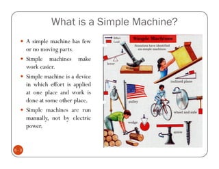
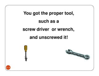
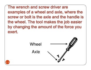
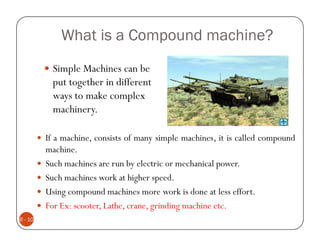
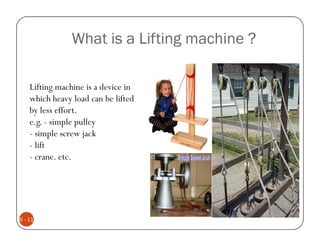
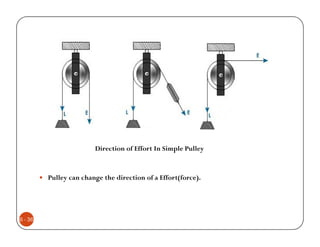
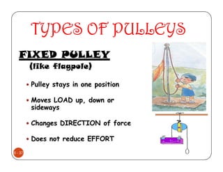
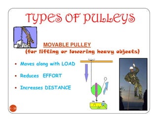
Jaydeep Patel
School of Technology,

6
Machine – a tool that helps us do
      work

      Machines help us by:

      1.   Changing the amount of force on an object.

      2.   Changing the direction of the force.


6-2
What is a Simple Machine?
      A simple machine has few
      or no moving parts.
      Simple machines make
      work easier.
      Simple machine is a device
      in which effort is applied
      at one place and work is
      done at some other place.
      Simple machines are run
      manually, not by electric
      power.


6-3
Have you ever tried to unscrew a nut, bolt,
      or screw from something with your bare
      hands and discovered that it was just too
      tight to loosen even if you had a good grip?


6-4
6-5
You got the proper tool,
             such as a
      screw driver or wrench,
         and unscrewed it!


6-6
Why is it that it's so easy to
      unscrew with a tool when
      you can't with your bare
      hands?


6-7
The wrench and screw driver are
 examples of a wheel and axle, where the
 screw or bolt is the axle and the handle is
 the wheel. The tool makes the job easier
 by changing the amount of the force you
 exert.


             Wheel
              Axle

6-8
All of the simple machines can be
       used for thousands of jobs from
        lifting a 500-pound weight to
      making a boat go. The reason why
       these machines are so special is
      because they make difficult tasks
                  much easier.


6-9
What is a Compound machine?
           Simple Machines can be
           put together in different
           ways to make complex
           machinery.

         If a machine, consists of many simple machines, it is called compound
         machine.
         Such machines are run by electric or mechanical power.
         Such machines work at higher speed.
         Using compound machines more work is done at less effort.
         For Ex: scooter, Lathe, crane, grinding machine etc.
6 - 10
What is a Lifting machine ?

    Lifting machine is a device in
    which heavy load can be lifted
    by less effort.
    e.g. - simple pulley
    - simple screw jack
    - lift
    - crane. etc.


6 - 11
Technical terms Related to Simple Machines
          Mechanical advantage (MA) :
          The ratio of load lifted (W) and effort required (P) is called Mechanical
          advantage.
                              Load Lifted           W
                      MA =                   ∴ MA =
                             Effort required        P
                                 Where, W= Load and P= Effort


          Velocity ratio (VR) :
          The ratio of distance moved by effort and the distance moved by load is
          called velocity ratio.
                        Distance moved by effort        y
                 VR =                            ∴ VR =
                        Distance moved by load          x


6 - 12
Input
               Input = effort x distance moved by effort
               Input = p.y
           Output:
               Output = load x distance moved by load
               Output = W.x
         • Efficiency ( η ) :
               The ratio of work done by the machine and work done on the machine is called
               efficiency of the machine.
                                 output
                   Efficiency   =       × 100 %
                                  input
                   Output = W . x & input = P . y
                         W.x          W/P
                  ∴η =        × 100 =                 × 100
                         P.y           y/x
                         MA
                       =     × 100 %
6 - 13
                         VR
Ideal machine :
              A machine having 100% efficiency is called an ideal machine.
              In an Ideal machine friction is zero.
              For Ideal machine,
                Output = input or MA=VR

         Effort lost in friction (Pf):
         In a simple machine, effort required to overcome the friction between
         various parts of a machine is called effort lost in friction.
         Let, P = effort
                                             •   effort lost in friction.
             Po = effort for Ideal machine
                                                       Pf=P - Po
             Pf = effort lost in friction
                                                 For Ideal machine,VR = MA
                                                         VR=W/Po
                                                         Po=W/VR
                                                         Pf = P-Po
                                                         Pf= P-(W/VR)
6 - 14
Reversible machine :
           If a machine is capable of doing some work in the reverse direction, after the
           effort is removed is called reversible machine.
           For reversible machine, η ≥ 50%


        Non-reversible machine or self-locking machine
           If a machine is not capable of doing some work in the reverse direction, after the
           effort is removed, is called non-reversible machine or self-locking machine.
           For non-reversible machine, η < 50%
           A car resting on a screw jack does not come down on the removal of the effort.
           It is an example of non-reversible machine.


6- 15
Condition for reversibility of machine :
           W = load lifted
           P = effort required
           x = distance moved by load
           y = distance moved by effort
           P.y = input
           W.x = output
         Machine friction = P.y – W.x
         for a machine to reverse,
          output > machine friction
           ∴ W.x > P.y – W.x
           ∴ 2 W.x > p.y
              W. x    1
           ∴        ≥
              P. y    2
             Output
           ∴          ≥ 0 .5
              Input
           ∴ η ≥ 50%
6 - 16     For a machine to reverse, η ≥ 50%
Law of machine
          The law of machine is given by relation,
          P= mW+C
          Where,
           P = effort applied
           W= load lifted
           m = constant
                (coefficient of friction)
               = slope of line AB
           C= Constant
             = Machine Friction= OA
         Following observations are made from the graph :
         On a machine, if W = 0, effort C is required to run the machine. Hence, effort C is required
         to overcome machine friction.
         If line AB crosses x-x axis. without effort (P), some load call be lifted, which is impossible.
         Hence, line AB never crosses x-x axis.
         If line AB passes through origin, no effort is required to balance friction. Such a graph is for
         Ideal machine.
6 - 17
Maximum mechanical advantage
            W
     MA =
            P
     from law of machine P = mW + C
                W               1                     C
     ∴ MA =                 =         (Q neglecting     )
              mW + C              C                   W
                              m+
                                  W
                  1
     Maxi. MA =
                 m


         Maximum efficiency (η max )
                                                     W
                                              MA =
                                                      P
                                              from law of machine P = mW + C
                                                    MA
                                              ∴η =
                                                     VR

                                                      1
                                                       m                       1
                                              ∴η =            (MA = MA max =     )
                                                      VR                       m
                                                                 1
                                                  ∴ η max =
6 - 18                                                        m x VR
Relation Between Load Lifted and the Mechanical Advantage

     As the load increases, the effort also increases
     and the M. A. increases
     The maximum M. A. is equal to 1/m.


         Relation Between Load Lifted and the Efficiency

                                             As the load and effort increases, efficiency also
                                             increases.
                                             The maximum efficiency is equal to 1/(m x VR)


6 - 19
Simple Machine
         • Following are the simple machines.
                Simple Wheel and Axle
                Differential wheel and axle
               Worm and Worm Wheel
                Single purchase Crab
                Double Purchase Crab
                Simple Screw Jack
                lever
              Simple Pulley


6 - 20
Simple Wheel and Axle
WHEEL AND AXLE : A wheel and
axle is a modification of a pulley.

A wheel is fixed to a shaft.

Large wheel fixed to smaller wheel (or
shaft) called an axle

Both turn together

Effort usually on larger wheel, moving
load of axle
6 - 22
When either the wheel or axle turns,
         the other part also turns. One full
         revolution of either part causes one full
         revolution of the other part.


6 - 23
DIFFERENTIAL WHEEL AND AXLE


         • In this machine load axle is made in two parts having two different diameters d1 and d2.
         • When effort is applied to rotate the assembly at that time string is wound over larger
         axle (d1) and unwound from the smaller axle (d2).
6 - 24
WORM AND WORM WHEEL


   • In worm and worm wheel machine, effort wheel and worm are on the same shaft and rotates in
   two bearings as shown.
   • Similarly worm wheel and load drum are also on the same shaft and rotates in two bearings. Two
   axes are at right angles.
6 - 25
CRAB WINCH

         Winch crabs are lifting machines in which velocity
         ratio is increased by a gear system.
         If only one set of gears is used, the winch crab is
         called a single purchase winch crab and if two sets
         are used it is called double purchase winch crab.


6 - 26
SINGLE PURCHASE CRAB WINCH


6 - 27
DOUBLE PURCHASE CRAB WINCH


         • In this machine to increase the V.R. one more pair of gears is used in comparison to single
         purchase crab.
         • Since there are totally two pairs of gears it is known as Double Purchase Crab Winch. Similarly in
         Triple Purchase CrabWinch there will be three pairs of gears.
         • Construction is similar in all the cases


6 - 28
SIMPLE SCREW JACK
         Screw Jack is a simple machine used for lifting heavy
         loads, through short distances, with the help of small
         effort applied at its handle.
         The most common application of screw jack is the
         raising of the front or rear portion of a vehicle for
         the purpose of changing the wheel or tyre.
         when one rotation is given to the handle.
         distance moved by effort = 2πR
         distance through which load is lifted = p


6 - 29
LEVERS

    The lever is simple machine made with a bar
    free to move about a fixed point called
    fulcrum.
    It enables a small effort to overcome a large
    load.


                                               VR = dE/dL
6 - 30                                         ME = FL/FE
First Kind of lever
    In a first Kind lever the fulcrum is in
    between of load and effort.
    load and effort is on either side.


6 - 31
Second Kind of lever

    In a second kind lever the fulcrum is at the
    end, with the load is in between fulcrum
    and effort.


6 - 32
Third Kind of lever

    In a third kind lever the fulcrum is again at
    the end, but the effort is in the middle.


6 - 33
Summary of LEVER CLASSES


          1st Class                        2nd Class                               3rd Class
    Fulcrum is between the load and      Load is between fulcrum and effort    •Effort is between the fulcrum and
    effort                                                                     load.
    • Mechanical advantage               • MA = b/a                            •MA = b/a
    • MA = effort arm/load arm           • MA is always greater than 1.        • MA is always less than 1
        MA= b/a
    • MA can be more than 1,
    equal to 1 or less than 1.
    When MA is greater than 1, less      Since. MA is always greater than 1.   Since, MA is always less
    effort would be required to lift a   lever of second kind is an effort     than 1. lever of the third
    heavy load. Such type of lever is    multiplier lever.                     kind is only a speed multiplier
    called effort multiplier lever.                                            lever. Such levers cannot lift heavy
                                                                               loads but provide increase in speed
                                                                               of lifting.

6 - 34
Simple Pulley
     PULLEY: A pulley is a simple machine
     made with a rope, belt or chain wrapped
     around a grooved wheel.

     A pulley works two ways. It can change the
     direction of a force or it can change the
     amount of force.

         A fixed pulley changes the direction of the
         applied force. ( Ex. Raising the flag ) .
         A movable pulley is attached to the object are
         moving.
6 - 35
Direction of Effort In Simple Pulley


         Pulley can change the direction of a Effort(force).


6 - 36
TYPES OF PULLEYS
   FIXED PULLEY
         (like flagpole)

         Pulley stays in one position

         Moves LOAD up, down or
         sideways

         Changes DIRECTION of force

         Does not reduce EFFORT
6 - 37
TYPES OF PULLEYS

                 MOVABLE PULLEY
          (for lifting or lowering heavy objects)

         Moves along with LOAD

         Reduces EFFORT

         Increases DISTANCE


6 - 38
System OF PULLEYS
         First system of pulleys

         Second system of pulleys

         Third system of pulleys


6 - 39
First system of pulleys


         First system of pulley : VR = 2n
         Where, n = no. of moving Pulley

6 - 40
Second system of pulleys


         Second system of pulley: VR = n
         Where, n =total no. of Pullies.
6 - 41
Third system of pulleys


 Third system of pulley : VR = 2n - 1
 Where, n = total no. of Pullies.


6 - 42

Chapter 6

  • 1.
  • 2.
    Machine – atool that helps us do work Machines help us by: 1. Changing the amount of force on an object. 2. Changing the direction of the force. 6-2
  • 3.
    What is aSimple Machine? A simple machine has few or no moving parts. Simple machines make work easier. Simple machine is a device in which effort is applied at one place and work is done at some other place. Simple machines are run manually, not by electric power. 6-3
  • 4.
    Have you evertried to unscrew a nut, bolt, or screw from something with your bare hands and discovered that it was just too tight to loosen even if you had a good grip? 6-4
  • 5.
  • 6.
    You got theproper tool, such as a screw driver or wrench, and unscrewed it! 6-6
  • 7.
    Why is itthat it's so easy to unscrew with a tool when you can't with your bare hands? 6-7
  • 8.
    The wrench andscrew driver are examples of a wheel and axle, where the screw or bolt is the axle and the handle is the wheel. The tool makes the job easier by changing the amount of the force you exert. Wheel Axle 6-8
  • 9.
    All of thesimple machines can be used for thousands of jobs from lifting a 500-pound weight to making a boat go. The reason why these machines are so special is because they make difficult tasks much easier. 6-9
  • 10.
    What is aCompound machine? Simple Machines can be put together in different ways to make complex machinery. If a machine, consists of many simple machines, it is called compound machine. Such machines are run by electric or mechanical power. Such machines work at higher speed. Using compound machines more work is done at less effort. For Ex: scooter, Lathe, crane, grinding machine etc. 6 - 10
  • 11.
    What is aLifting machine ? Lifting machine is a device in which heavy load can be lifted by less effort. e.g. - simple pulley - simple screw jack - lift - crane. etc. 6 - 11
  • 12.
    Technical terms Relatedto Simple Machines Mechanical advantage (MA) : The ratio of load lifted (W) and effort required (P) is called Mechanical advantage. Load Lifted W MA = ∴ MA = Effort required P Where, W= Load and P= Effort Velocity ratio (VR) : The ratio of distance moved by effort and the distance moved by load is called velocity ratio. Distance moved by effort y VR = ∴ VR = Distance moved by load x 6 - 12
  • 13.
    Input Input = effort x distance moved by effort Input = p.y Output: Output = load x distance moved by load Output = W.x • Efficiency ( η ) : The ratio of work done by the machine and work done on the machine is called efficiency of the machine. output Efficiency = × 100 % input Output = W . x & input = P . y W.x W/P ∴η = × 100 = × 100 P.y y/x MA = × 100 % 6 - 13 VR
  • 14.
    Ideal machine : A machine having 100% efficiency is called an ideal machine. In an Ideal machine friction is zero. For Ideal machine, Output = input or MA=VR Effort lost in friction (Pf): In a simple machine, effort required to overcome the friction between various parts of a machine is called effort lost in friction. Let, P = effort • effort lost in friction. Po = effort for Ideal machine Pf=P - Po Pf = effort lost in friction For Ideal machine,VR = MA VR=W/Po Po=W/VR Pf = P-Po Pf= P-(W/VR) 6 - 14
  • 15.
    Reversible machine : If a machine is capable of doing some work in the reverse direction, after the effort is removed is called reversible machine. For reversible machine, η ≥ 50% Non-reversible machine or self-locking machine If a machine is not capable of doing some work in the reverse direction, after the effort is removed, is called non-reversible machine or self-locking machine. For non-reversible machine, η < 50% A car resting on a screw jack does not come down on the removal of the effort. It is an example of non-reversible machine. 6- 15
  • 16.
    Condition for reversibilityof machine : W = load lifted P = effort required x = distance moved by load y = distance moved by effort P.y = input W.x = output Machine friction = P.y – W.x for a machine to reverse, output > machine friction ∴ W.x > P.y – W.x ∴ 2 W.x > p.y W. x 1 ∴ ≥ P. y 2 Output ∴ ≥ 0 .5 Input ∴ η ≥ 50% 6 - 16 For a machine to reverse, η ≥ 50%
  • 17.
    Law of machine The law of machine is given by relation, P= mW+C Where, P = effort applied W= load lifted m = constant (coefficient of friction) = slope of line AB C= Constant = Machine Friction= OA Following observations are made from the graph : On a machine, if W = 0, effort C is required to run the machine. Hence, effort C is required to overcome machine friction. If line AB crosses x-x axis. without effort (P), some load call be lifted, which is impossible. Hence, line AB never crosses x-x axis. If line AB passes through origin, no effort is required to balance friction. Such a graph is for Ideal machine. 6 - 17
  • 18.
    Maximum mechanical advantage W MA = P from law of machine P = mW + C W 1 C ∴ MA = = (Q neglecting ) mW + C C W m+ W 1 Maxi. MA = m Maximum efficiency (η max ) W MA = P from law of machine P = mW + C MA ∴η = VR 1 m 1 ∴η = (MA = MA max = ) VR m 1 ∴ η max = 6 - 18 m x VR
  • 19.
    Relation Between LoadLifted and the Mechanical Advantage As the load increases, the effort also increases and the M. A. increases The maximum M. A. is equal to 1/m. Relation Between Load Lifted and the Efficiency As the load and effort increases, efficiency also increases. The maximum efficiency is equal to 1/(m x VR) 6 - 19
  • 20.
    Simple Machine • Following are the simple machines. Simple Wheel and Axle Differential wheel and axle Worm and Worm Wheel Single purchase Crab Double Purchase Crab Simple Screw Jack lever Simple Pulley 6 - 20
  • 21.
    Simple Wheel andAxle WHEEL AND AXLE : A wheel and axle is a modification of a pulley. A wheel is fixed to a shaft. Large wheel fixed to smaller wheel (or shaft) called an axle Both turn together Effort usually on larger wheel, moving load of axle
  • 22.
  • 23.
    When either thewheel or axle turns, the other part also turns. One full revolution of either part causes one full revolution of the other part. 6 - 23
  • 24.
    DIFFERENTIAL WHEEL ANDAXLE • In this machine load axle is made in two parts having two different diameters d1 and d2. • When effort is applied to rotate the assembly at that time string is wound over larger axle (d1) and unwound from the smaller axle (d2). 6 - 24
  • 25.
    WORM AND WORMWHEEL • In worm and worm wheel machine, effort wheel and worm are on the same shaft and rotates in two bearings as shown. • Similarly worm wheel and load drum are also on the same shaft and rotates in two bearings. Two axes are at right angles. 6 - 25
  • 26.
    CRAB WINCH Winch crabs are lifting machines in which velocity ratio is increased by a gear system. If only one set of gears is used, the winch crab is called a single purchase winch crab and if two sets are used it is called double purchase winch crab. 6 - 26
  • 27.
  • 28.
    DOUBLE PURCHASE CRABWINCH • In this machine to increase the V.R. one more pair of gears is used in comparison to single purchase crab. • Since there are totally two pairs of gears it is known as Double Purchase Crab Winch. Similarly in Triple Purchase CrabWinch there will be three pairs of gears. • Construction is similar in all the cases 6 - 28
  • 29.
    SIMPLE SCREW JACK Screw Jack is a simple machine used for lifting heavy loads, through short distances, with the help of small effort applied at its handle. The most common application of screw jack is the raising of the front or rear portion of a vehicle for the purpose of changing the wheel or tyre. when one rotation is given to the handle. distance moved by effort = 2πR distance through which load is lifted = p 6 - 29
  • 30.
    LEVERS The lever is simple machine made with a bar free to move about a fixed point called fulcrum. It enables a small effort to overcome a large load. VR = dE/dL 6 - 30 ME = FL/FE
  • 31.
    First Kind oflever In a first Kind lever the fulcrum is in between of load and effort. load and effort is on either side. 6 - 31
  • 32.
    Second Kind oflever In a second kind lever the fulcrum is at the end, with the load is in between fulcrum and effort. 6 - 32
  • 33.
    Third Kind oflever In a third kind lever the fulcrum is again at the end, but the effort is in the middle. 6 - 33
  • 34.
    Summary of LEVERCLASSES 1st Class 2nd Class 3rd Class Fulcrum is between the load and Load is between fulcrum and effort •Effort is between the fulcrum and effort load. • Mechanical advantage • MA = b/a •MA = b/a • MA = effort arm/load arm • MA is always greater than 1. • MA is always less than 1 MA= b/a • MA can be more than 1, equal to 1 or less than 1. When MA is greater than 1, less Since. MA is always greater than 1. Since, MA is always less effort would be required to lift a lever of second kind is an effort than 1. lever of the third heavy load. Such type of lever is multiplier lever. kind is only a speed multiplier called effort multiplier lever. lever. Such levers cannot lift heavy loads but provide increase in speed of lifting. 6 - 34
  • 35.
    Simple Pulley PULLEY: A pulley is a simple machine made with a rope, belt or chain wrapped around a grooved wheel. A pulley works two ways. It can change the direction of a force or it can change the amount of force. A fixed pulley changes the direction of the applied force. ( Ex. Raising the flag ) . A movable pulley is attached to the object are moving. 6 - 35
  • 36.
    Direction of EffortIn Simple Pulley Pulley can change the direction of a Effort(force). 6 - 36
  • 37.
    TYPES OF PULLEYS FIXED PULLEY (like flagpole) Pulley stays in one position Moves LOAD up, down or sideways Changes DIRECTION of force Does not reduce EFFORT 6 - 37
  • 38.
    TYPES OF PULLEYS MOVABLE PULLEY (for lifting or lowering heavy objects) Moves along with LOAD Reduces EFFORT Increases DISTANCE 6 - 38
  • 39.
    System OF PULLEYS First system of pulleys Second system of pulleys Third system of pulleys 6 - 39
  • 40.
    First system ofpulleys First system of pulley : VR = 2n Where, n = no. of moving Pulley 6 - 40
  • 41.
    Second system ofpulleys Second system of pulley: VR = n Where, n =total no. of Pullies. 6 - 41
  • 42.
    Third system ofpulleys Third system of pulley : VR = 2n - 1 Where, n = total no. of Pullies. 6 - 42