Downloaded 2,551 times

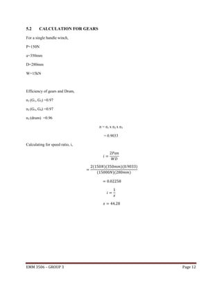

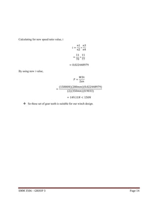
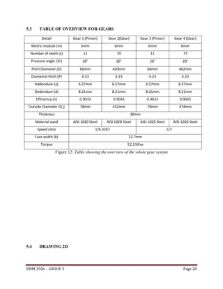
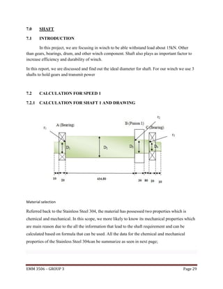
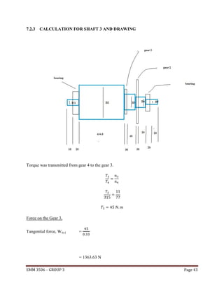
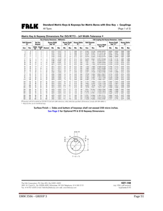
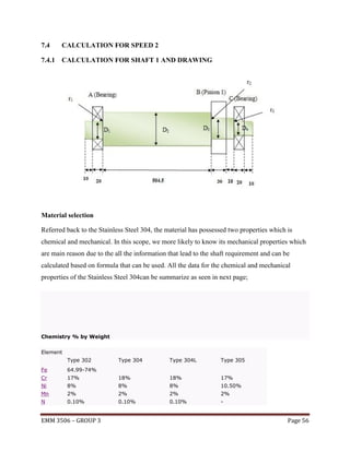
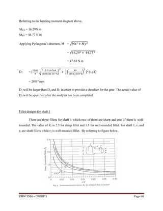
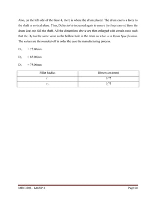
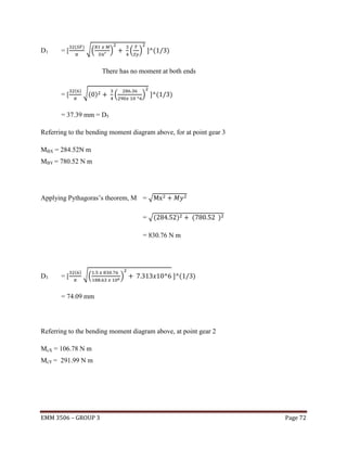
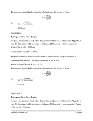
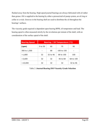
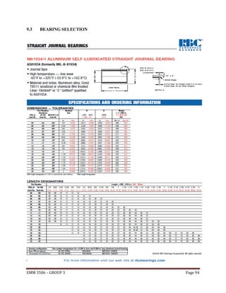
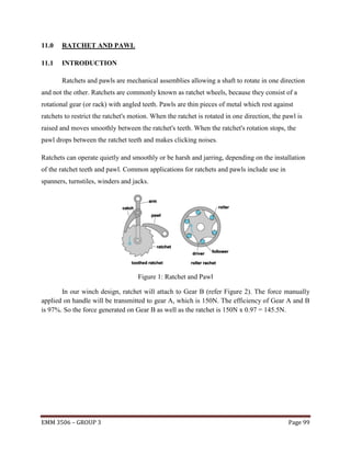
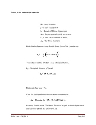
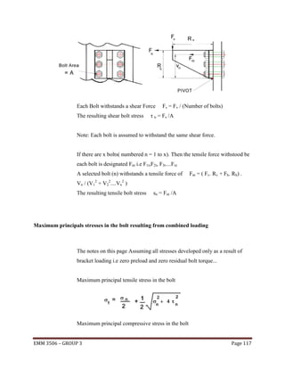
![Speed ratio:
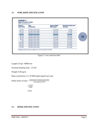
Number of teeth (n) of gears:
Number of teeth of gear 1, Z1
=
11
Number of teeth of gear 2, Z2
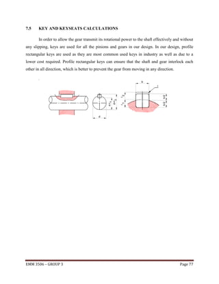
=
70
Number of teeth of gear 3, Z3
=
11
Number of teeth of gear 4, Z4
=
77
*no. of teeth obtained by comparing with speed ratio
Efficiency of gear:
n1 [G1, G2] = 0.97
n2 [G3, G4] = 0.97
n3 [drum] = 0.96
n=n1 x n2 x n3
=0.9033
Pressure angle, Φ:
Φ = 20˚ (commonly used for designer)
Pitch diameter (D) of gears:
relationship:
Pitch diameter of gear 1, D1 = 66mm
Pitch diameter of gear 2, D2 = 420mm
Pitch diameter of gear 3, D3 = 66mm
Pitch diameter of gear 4, D4 = 462mm
Diametral Pitch (P):
EMM 3506 – GROUP 3
Page 15](https://image.slidesharecdn.com/finalreportdesign-140110104940-phpapp01/85/introduction-drawing-calculation-for-winch-design-15-320.jpg)

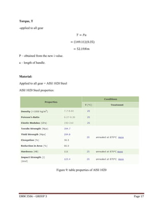
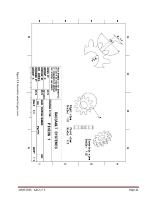


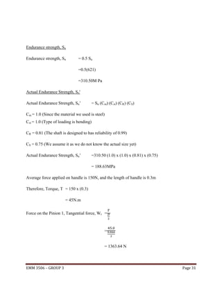


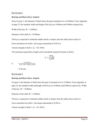
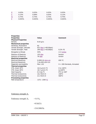
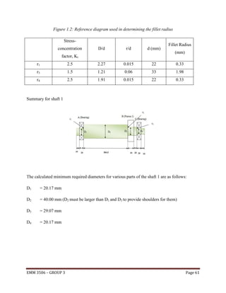
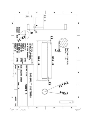
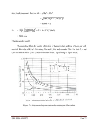

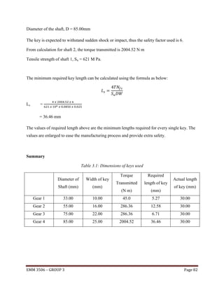
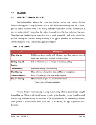

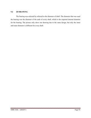

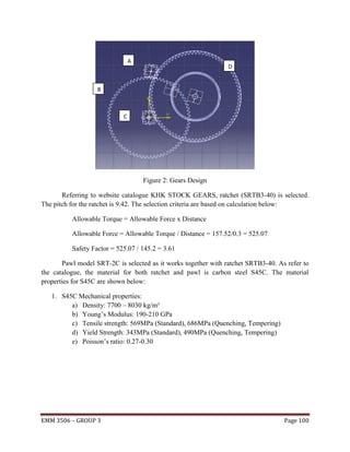
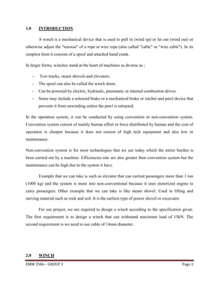
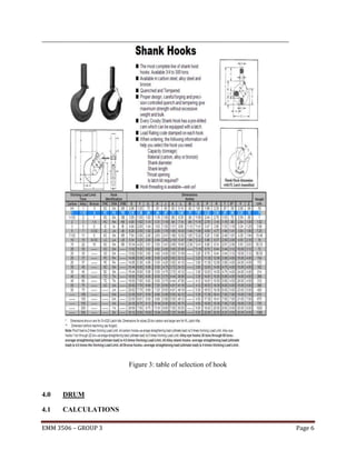
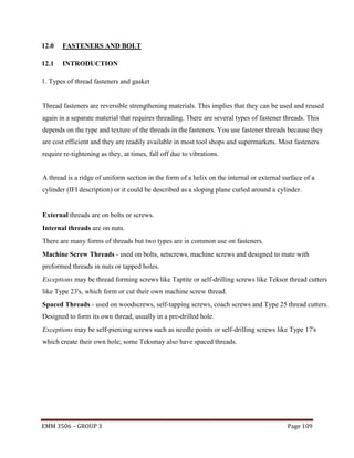
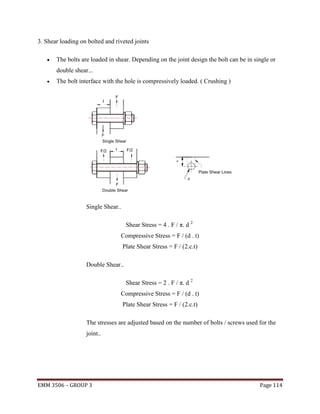
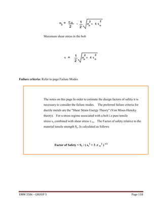
![Pawls
Catalog No.
SRT2/3-C
J
5
K
8
L
38
M
30
N
6
Shape Weight(kgf)
T5
0.02
8
10
49
39 12
T5
0.05
10 12.5 67.5 55 15
T5
0.12
12
15
80
65 20
T5
0.22
13
18
98
80 25
T5
0.3
[DXF | DWG | 3D CAD]
SRT1-C
[DXF | DWG | 3D CAD]
SRT2-C
[DXF | DWG | 3D CAD]
SRT3-C
[DXF | DWG | 3D CAD]
SRT4-C
[DXF | DWG | 3D CAD]
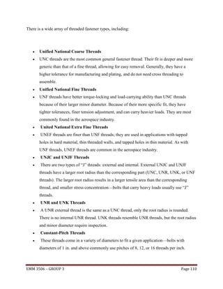
Ratchets
Catalog
No.
Pit
ch
P
SRT1-50
[DXF | DW
G | 3D
CAD]
SRT1-60
[DXF | DW
G | 3D
CAD]
SRT1-80
[DXF | DW
G | 3D
CAD]
SRT1-90
[DXF | DW
G | 3D
CAD]
SRT1100
3.
14
No
.
of
te
et
h
z
B
or
e
Outsi
de
dia.
Face
widt
h
Dep
th
of
teet
h
Mou
ntin
g
dista
nce
Center
distanc
e
A
C
F
G
H
I
50
1
2
50
12
1.6
23.4
45.5
60
28.4
80
60
80
90
10
0
We
igh
t
(kg
f)
Catal
og
No.
0.1
6
SRT150
0.2
4
SRT160
0.4
4
SRT180
1
5
0.5
6
SRT190
1
5
0.7
SRT1100
1
5
1
5
Sh
ap
e
Allowa
ble
torque
(kgf-m)
Allow
able
torqu
e (Nm)
Bendin
g
strengt
h
1.5
Bendi
ng
streng
th
14.69
48.2
1.99
19.5
38.4
54.7
3
29.37
90
43.4
58.3
3.52
34.47
100
48.4
62.2
4.02
39.4
T4
[DXF | DW
G | 3D
CAD]
EMM 3506 – GROUP 3
Page 102](https://image.slidesharecdn.com/finalreportdesign-140110104940-phpapp01/85/introduction-drawing-calculation-for-winch-design-102-320.jpg)
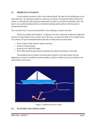
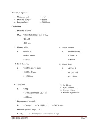
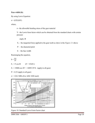
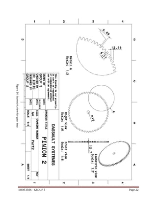
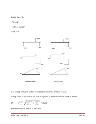
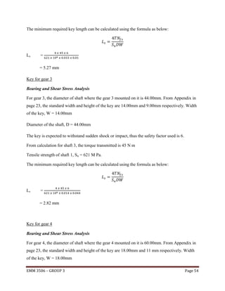
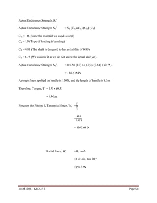
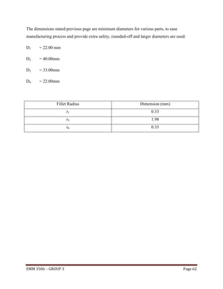
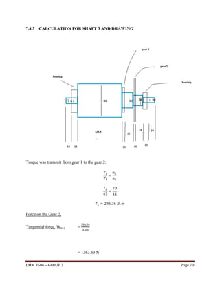
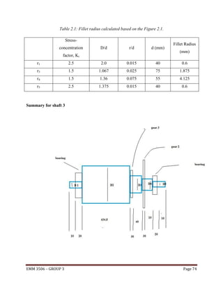
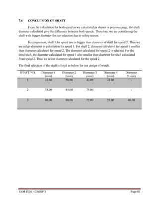
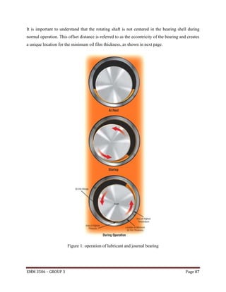
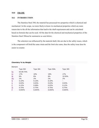
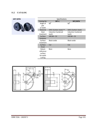
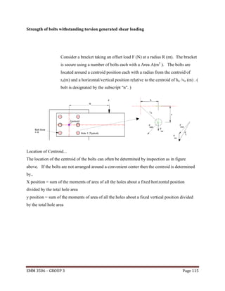
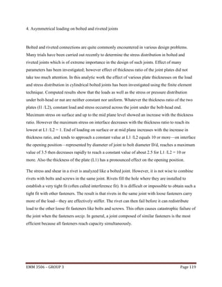
![SRT2-30
[DXF | DW
G | 3D
CAD]
6.
28
SRT2-40
30
40
50
[DXF | DW
G | 3D
CAD]
60
SRT2-50
[DXF | DW
G | 3D
CAD]
[DXF | DW
G | 3D
CAD]
[DXF | DW
G | 3D
CAD]
9.
42
SRT3-40
30
40
50
[DXF | DW
G | 3D
CAD]
[DXF | DW
G | 3D
CAD]
[DXF | DW
G | 3D
CAD]
SRT4-40
[DXF | DW
G | 3D
CAD]
SRT4-50
[DXF | DW
G | 3D
CAD]
1
5
15
3.1
26.9
61.2
80
36.9
100
120
T4
2.96
29.03
66.2
5.02
49.22
46.9
72.3
7.22
70.82
56.9
79.1
9.61
94.28
0.2
8
SRT230
0.5
3
SRT240
0.8
6
SRT250
1.2
4
1
5
2
0
90
20
5
40
76.3
120
55
150
70
T4
SRT260
0.8
6
SRT330
1.5
8
SRT340
2.5
4
SRT350
225.9
2
1.9
1
SRT430
385.1
4
3.5
4
SRT440
559.4
5.6
8
SRT450
9.44
92.56
85.1
16.06
95.5
23.31
157.5
2
228.6
2
2
0
SRT3-50
SRT4-30
1
5
60
1
5
SRT2-60
SRT3-30
1
5
12
.5
6
30
40
50
2
0
2
0
2
0
EMM 3506 – GROUP 3
120
25
7.4
52.6
95.7
T4
23.04
160
72.6
108
39.27
200
92.6
122.4
57.04
Page 103](https://image.slidesharecdn.com/finalreportdesign-140110104940-phpapp01/85/introduction-drawing-calculation-for-winch-design-103-320.jpg)
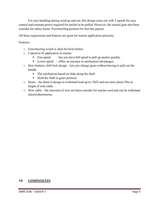
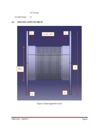
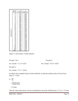
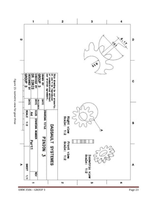
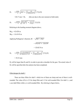
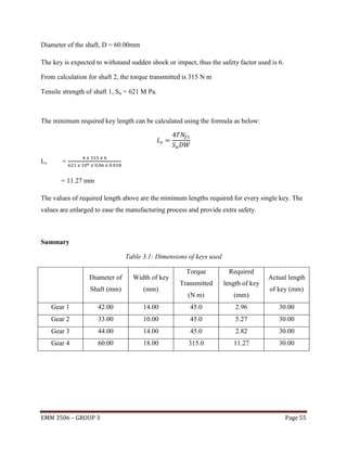
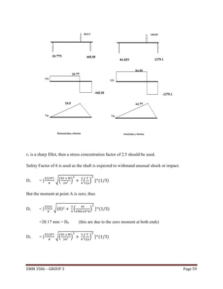
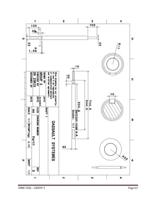
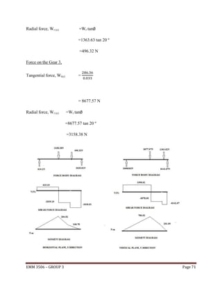
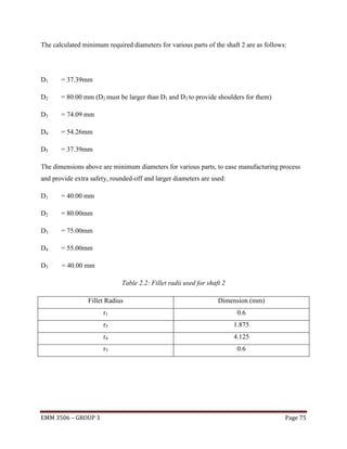
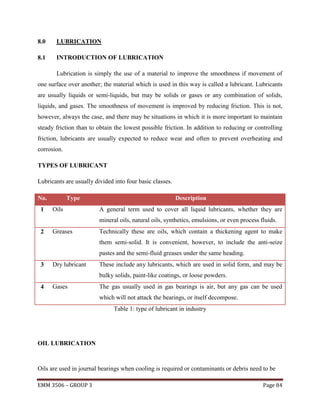
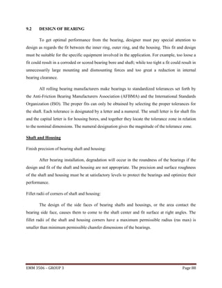
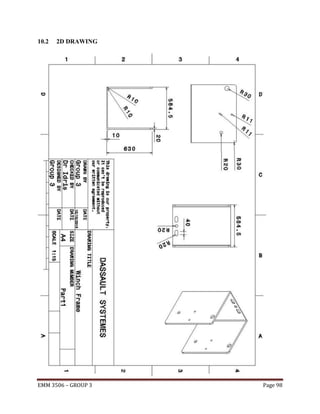
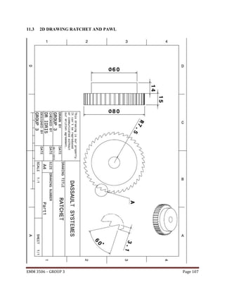
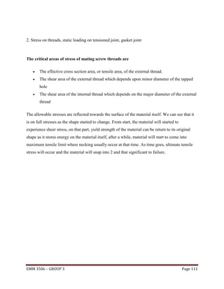
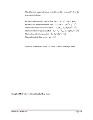
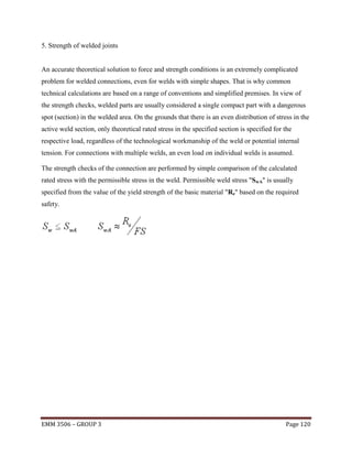
![Ratchets with Hubs
Catalo
g No.
[DXF | D
WG | 3D
CAD]
N
o.
of
te
et
h
B
o
r
e
Hu
b
dia
.
Out
side
dia.
Fac
e
wid
th
Hu
b
wid
th
Tot
al
leng
th
De
pth
of
tee
th
Mo
unt
ing
dist
anc
e
Cent
er
dista
nce
P
SRTB2
/3-50
Pi
tc
h
z
A
B
C
D
E
F
G
H
I
2.
0
9
5
0
1
0
25
33.3
6
10
16
1
33.8
30
40
15.
5
6
0
1
0
8
0
1
2
9
0
1
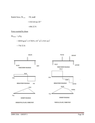
2
1
0
0
1
2
SRTB2
/3-60
[DXF | D
WG | 3D
CAD]
SRTB2
/3-80
[DXF | D
WG | 3D
CAD]
SRTB2
/3-90
35
19
53.3
40
60
25.
5
40
66.6
29
35.5
S
h
a
p
e
T
9
Allo
wabl
e
torq
ue
(kgfm)
Bend
ing
stren
gth
0.31
0.42
Allo W Cata
wabl ei
log
e
gh No.
torq t
ue
(k
(N- gf)
m)
Ben
ding
stre
ngth
3.07 0. SRT
06 B2/3
4.1 7
-50
39.4
0.61
6
41.7
0.73
7.11
43.9
0.84
8.24
32
0.
1
0.
16
0.
21
0.
24
[DXF | D
WG | 3D
CAD]
SRT
B2/3
-60
SRT
B2/3
-80
SRT
B2/3
-90
SRT
B2/3
-100
SRTB2
/3100
[DXF | D
WG | 3D
CAD]
SRTB1
-50
[DXF | D
WG | 3D
CAD]
SRTB1
-60
3.
1
4
5
0
1
2
6
0
1
5
35
50
40
60
50
80
50
EMM 3506 – GROUP 3
90
12
12
24
1.6
23.
4
28.
4
45.5
48.2
54.7
58.3
T
9
1.5
1.99
3
3.52
14.6
9
0.
24
19.5
0.
34
29.3
SRT
B150
SRT
B1-
Page 104](https://image.slidesharecdn.com/finalreportdesign-140110104940-phpapp01/85/introduction-drawing-calculation-for-winch-design-104-320.jpg)
![[DXF | D
WG | 3D
CAD]
8
0
9
0
[DXF | D
WG | 3D
CAD]
SRTB1
-90
[DXF | D
WG | 3D
CAD]
1
5
43.
4
1
0
0
SRTB1
-80
1
5
1
5
48.
4
50
38.
4
100
62.2
4.02
7
34.4
7
39.4
0.
61
0.
73
0.
87
[DXF | D
WG | 3D
CAD]
[DXF | D
WG | 3D
CAD]
6.
2
8
SRTB2
-50
1
5
4
0
1
5
1
5
6
0
[DXF | D
WG | 3D
CAD]
3
0
5
0
SRTB2
-40
50
60
60
80
1
5
60
14
29
3.1
26.
9
36.
9
100
65
15
120
46.
9
61.2
2.96
5.02
72.3
7.22
79.1
9.61
56.
9
29.0
3
0.
48
49.2
2
0.
82
70.8
2
1.
14
94.2
8
66.2
T
9
1.
59
[DXF | D
WG | 3D
CAD]
[DXF | D
WG | 3D
CAD]
[DXF | D
WG | 3D
CAD]
9.
4
2
[DXF | D
WG | 3D
CAD]
3
0
1
5
4
0
2
0
5
0
SRTB3
-40
75
90
80
85
20
16
36
5
40
76.3
120
55
85.1
150
70
T
9
95.5
2
0
9.44
16.0
6
23.3
1
92.5
6
1.
4
157.
52
2.
17
228.
62
3.
21
[DXF | D
WG | 3D
CAD]
[DXF | D
WG | 3D
CAD]
SRTB4
-40
[DXF | D
SRT
B230
SRT
B240
SRT
B250
SRT
B330
SRT
B340
SRT
B350
SRTB3
-50
SRTB4
-30
SRT
B190
SRT
B260
SRTB2
-60
SRTB3
-30
SRT
B180
SRT
B1100
SRTB1
-100
SRTB2
-30
60
1
2.
5
6
3
0
2
0
4
0
2
0
5
90
120
90
160
10
0
200
2
EMM 3506 – GROUP 3
25
18
43
7.4
52.
6
72.
6
92.
95.7
108
122.4
T
9
23.0
4
225.
92
2.
76
39.2
7
385.
14
4.
4
57.0
559.
6.
SRT
B430
SRT
B440
Page 105](https://image.slidesharecdn.com/finalreportdesign-140110104940-phpapp01/85/introduction-drawing-calculation-for-winch-design-105-320.jpg)
![WG | 3D
CAD]
0
0
SRTB4
-50
[DXF | D
WG | 3D
CAD]
EMM 3506 – GROUP 3
6
4
4
74
SRT
B450
Page 106](https://image.slidesharecdn.com/finalreportdesign-140110104940-phpapp01/85/introduction-drawing-calculation-for-winch-design-106-320.jpg)
![Le (min) = 2 . A t / [0.5 .π .(D - 0.64952.p )]
This assumes that the male and female thread materials have the same
strength. If the Female Material strength is lower i.e J as calculated below is
greater than 1 then the length of engagement must be increased to prevent the
female thread stripping
If the value of J is greater than 1 then the length of engagement must be
increased to at least
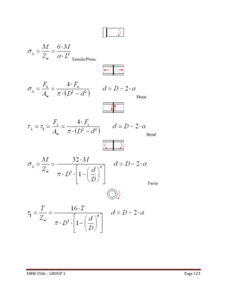
Thus from above method of calculation, we can see that is proven shows on how the calculation
is been made from one parts to another. This can also be applied to other parts regarding the
shapes and sizes. For certain cases, we need to consider the material use for the parts as it
involved the modulus young’s of that material. Everything can be found in any references book
and it is helpful in solving any problems.
EMM 3506 – GROUP 3
Page 113](https://image.slidesharecdn.com/finalreportdesign-140110104940-phpapp01/85/introduction-drawing-calculation-for-winch-design-113-320.jpg)
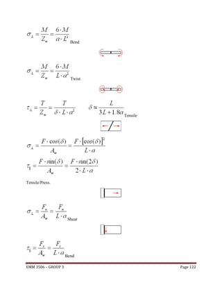
![6. Symmetrical loading on welded joints, brazing and soldering
Metalworking is the process of working with metals to create individual parts, assemblies, or
large-scale structures. The term covers a wide range of work from large ships and bridges to
precise engine parts and delicate jewelry. It therefore includes a correspondingly wide range of
skills, processes, and tools.
Metalworking is a science, art, hobby, industry and trade. Its historical roots span cultures,
civilizations, and millennia. Metalworking has evolved from the discovery
of smelting various ores, producing malleable and ductile metal useful for tools and adornments.
Modern metalworking processes, though diverse and specialized, can be categorized as forming,
cutting, or joining processes. Today's machine shop includes a number of machine tools capable
of creating a precise, useful work piece.
Here are some of the method of calculating load:
Load Rated stress [MPa, psi] Tensile/Press.
Shear
Bend
EMM 3506 – GROUP 3
Page 121](https://image.slidesharecdn.com/finalreportdesign-140110104940-phpapp01/85/introduction-drawing-calculation-for-winch-design-121-320.jpg)


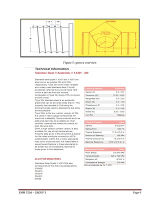
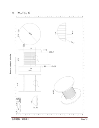
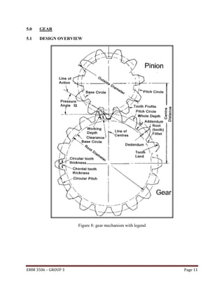
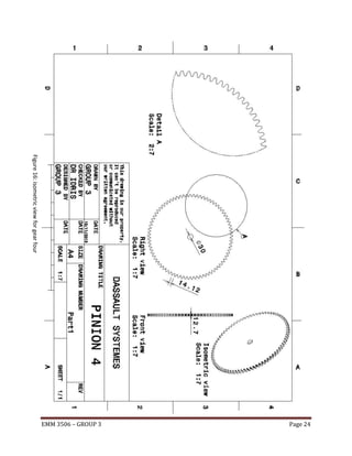
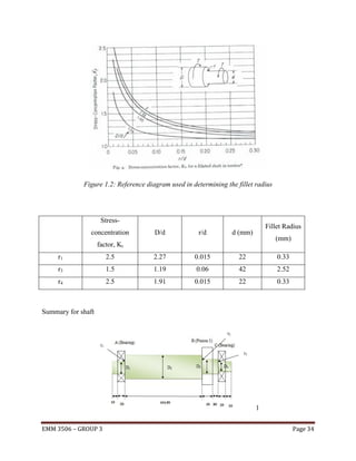
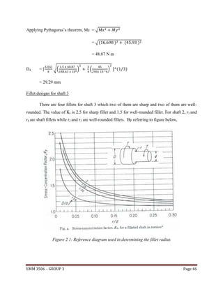
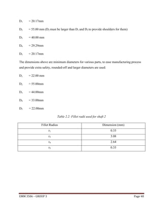
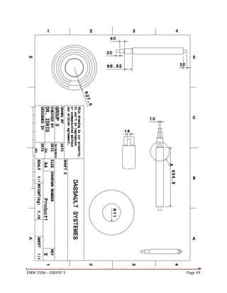
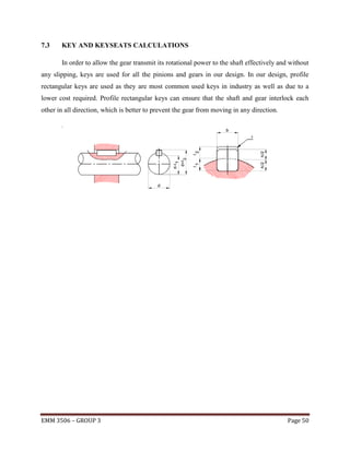
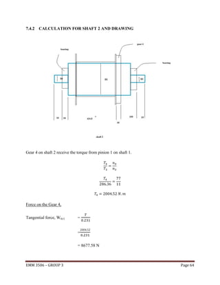
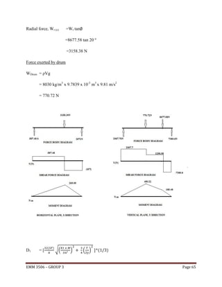
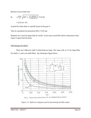
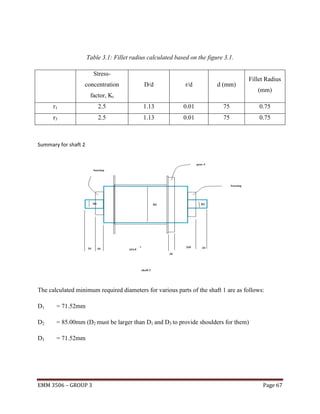
The document provides information about designing a winch that can withstand a maximum load of 15kN and uses a cable with a diameter of 14mm. It begins with an introduction to winches, their components, and operation systems. It then discusses the problem statement of designing a winch for pulling up boat anchors. The key design requirements are that it withstands 15kN of load and uses 14mm diameter cable. The summary discusses the components that will be included in the design - the wire rope, drum, gears, and other parts. It provides calculations for selecting the appropriate wire rope and determining the drum dimensions based on withstanding the load requirement. Gears are also designed with calculations of number of teeth