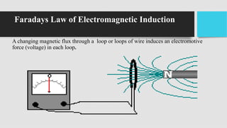
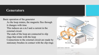
1) DC generators convert mechanical energy to electrical energy through Faraday's law of electromagnetic induction. When a conductor moves through a magnetic field, an EMF is induced in the conductor.
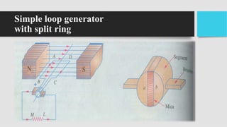
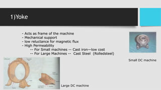
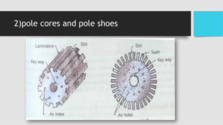
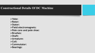
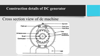
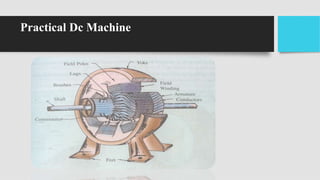
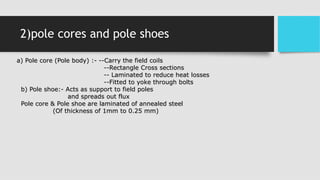
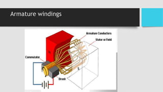
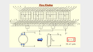
2) The main components of a DC generator are the yoke, field electromagnets, armature, commutator, and brushes. The armature is wound with coils and rotates within the magnetic field produced by the field electromagnets to generate an EMF.
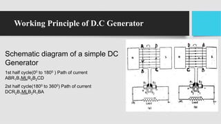
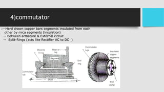
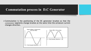
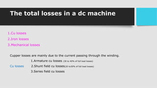
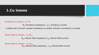
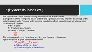
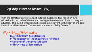
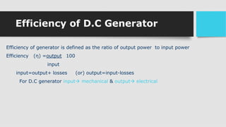
3) As the armature rotates, the commutator and brushes are used to periodically reverse the direction of current in the external circuit, thereby producing direct current. Losses in the generator arise from copper, iron, and mechanical components