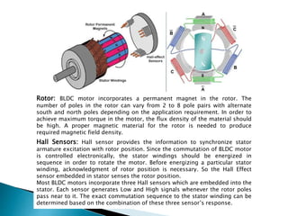
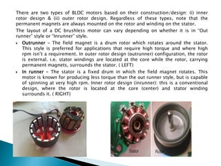
1. The document discusses the objectives, working principles, and types of DC motors. It describes brushed and brushless DC motors.
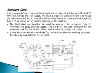
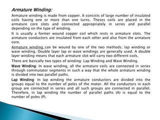
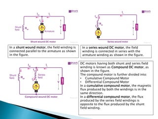
2. Key components of DC motors are described in detail, including the field structure, armature, commutator, brushes, yoke, poles, field and armature windings.
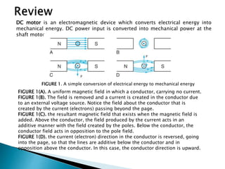
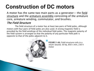
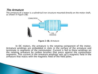
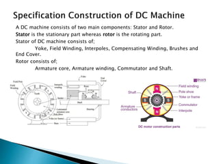
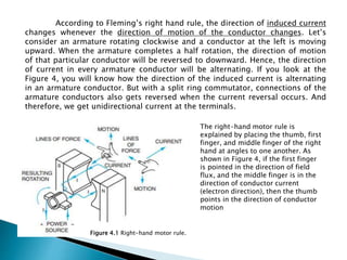
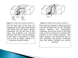
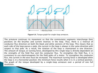
3. The document explains how electrical energy is converted to mechanical energy in a DC motor through electromagnetic interactions between the magnetic fields set up in the stationary and rotating components by currents.