Downloaded 1,232 times


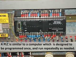

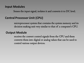
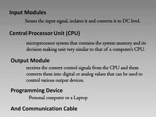
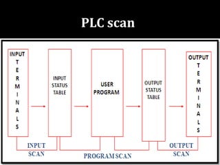

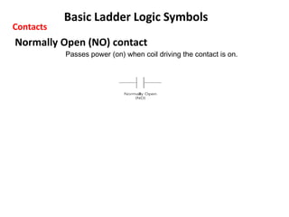
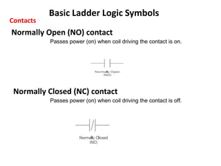
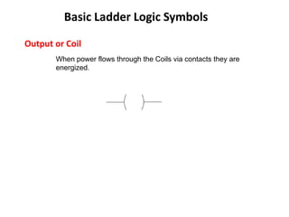
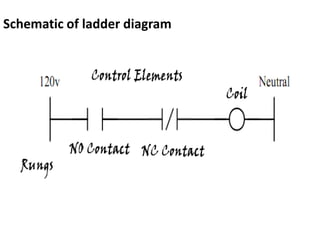
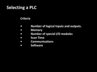
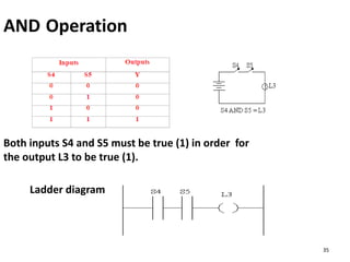
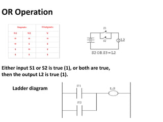
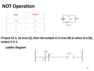
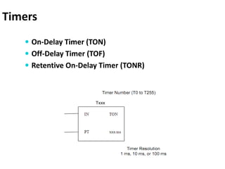
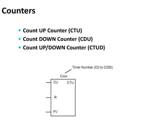

This document provides an introduction to programmable logic controllers (PLCs) and ladder logic programming. It defines a PLC as a small computer used to automate industrial processes by monitoring inputs and making decisions to control outputs based on a stored program. The document outlines the basic components of a PLC including input and output modules and the central processing unit. It then introduces ladder logic as the most common programming language for PLCs, describing the basic symbols of ladder diagrams including contacts, coils, and rungs. Finally, it provides examples of ladder logic programs for AND, OR, and NOT logic operations as well as timers and counters.