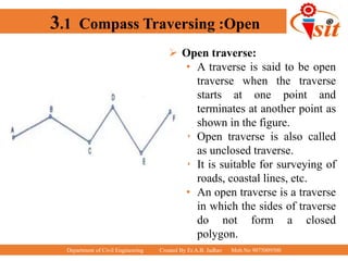
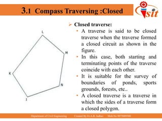
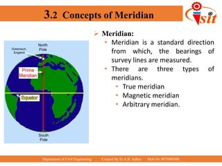
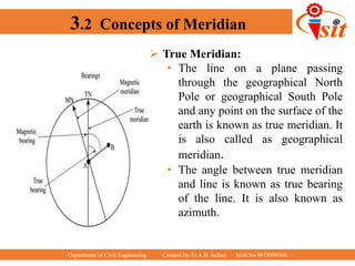
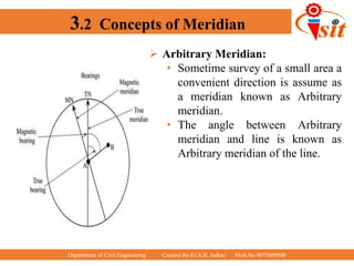
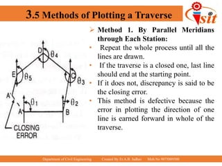
Department of Civil Engineering Created By Er.A.B. Jadhav Mob.No 9075009500
Basic Surveying
Presented By
Er. Ashish B.Jadhav
CO:-Conduct Traversing in the field using Chain &Compass
Department of Civil Engineering Created By Er.A.B. Jadhav Mob.No 9075009500
3.1 Compass Traversing :Open
 Open traverse:
• A traverse is said to be open
traverse when the traverse
starts at one point and
terminates at another point as
shown in the figure.
• Open traverse is also called
as unclosed traverse.
• It is suitable for surveying of
roads, coastal lines, etc.
• An open traverse is a traverse
in which the sides of traverse
do not form a closed
polygon.
Department of Civil Engineering Created By Er.A.B. Jadhav Mob.No 9075009500
3.1 Compass Traversing :Closed
 Closed traverse:
• A traverse is said to be closed
traverse when the traverse formed
a closed circuit as shown in the
figure.
• In this case, both starting and
terminating points of the traverse
coincide with each other.
• It is suitable for the survey of
boundaries of ponds, sports
grounds, forests, etc..
• A closed traverse is a traverse in
which the sides of a traverse form
a closed polygon.
Department of Civil Engineering Created By Er.A.B. Jadhav Mob.No 9075009500
3.2 Concepts of Meridian
 Meridian:
• Meridian is a standard direction
from which, the bearings of
survey lines are measured.
• There are three types of
meridians.
• True meridian
• Magnetic meridian
• Arbitrary meridian.
Department of Civil Engineering Created By Er.A.B. Jadhav Mob.No 9075009500
3.2 Concepts of Meridian
 True Meridian:
• The line on a plane passing
through the geographical North
Pole or geographical South Pole
and any point on the surface of the
earth is known as true meridian. It
is also called as geographical
meridian.
• The angle between true meridian
and line is known as true bearing
of the line. It is also known as
azimuth.
Department of Civil Engineering Created By Er.A.B. Jadhav Mob.No 9075009500
3.2 Concepts of Meridian
 Magnetic Meridian:
• When magnetic needle is
suspended freely and balance
properly , unaffected by magnetic
substance it indicate a direction
this direction is known as
magnetic meridian.
• The angle between magnetic
meridian and line is known as
magnetic bearing of the line.
Department of Civil Engineering Created By Er.A.B. Jadhav Mob.No 9075009500
3.2 Concepts of Meridian
 Arbitrary Meridian:
• Sometime survey of a small area a
convenient direction is assume as
a meridian known as Arbitrary
meridian.
• The angle between Arbitrary
meridian and line is known as
Arbitrary meridian of the line.
Department of Civil Engineering Created By Er.A.B. Jadhav Mob.No 9075009500
3.2 Concepts of Bearing
 Whole Circle Bearing:
• In this system, the bearing of a line is always
measured clock wise from the direction of the
North of the meridian towards the line around
the circle.
• Whole circle bearings of lines have been
shown in figure.
• If the survey line falls between the first
quadrant then the Whole Circle Bearing lies
between the 0° to 90°.
• If it lies between the second quadrant then
the Whole Circle Bearing of that survey line
lies between 90° to 180°. If it lies in the third
quadrant then the Whole circle bearing will
be between the 180° to 270°.
• And in the fourth quadrant, the Whole Circle
Bearing values range between 270° to 360°.
Department of Civil Engineering Created By Er.A.B. Jadhav Mob.No 9075009500
3.2 Concepts of Bearing
 Quadratic Bearing/Reduced Bearing:
• The Quadratic bearing is also known as
a Reduced bearing.
• Quadratic bearings are generally measured from the North or
South direction towards the East or West direction.
• The quadratic bearing or reduced bearing can be measured
either in a clockwise or anticlockwise direction.
• The quadratic bearing varies from 0° to 90°.
• In the quadratic bearing or reduced bearing system, the
bearings are taken either from the magnetic North or the
magnetic south direction. It will depend on which one is
nearer to that line.
• In the Quadratic bearing system, magnetic North and
magnetic South lines are considered as a reference line.
Department of Civil Engineering Created By Er.A.B. Jadhav Mob.No 9075009500
3.2 Concepts of Bearing
 Quadratic Bearing/Reduced Bearing:
• In the quadratic bearing system, you can take
both clockwise as well as the anticlockwise
angle from the reference line.
• It is necessary to state the particular quadrant
in which that line lies. The letters N(north),
S(south), E(east), and W( west) are used to
represent the quadrant.
• The quadrants are represented are as follows
• 1st quadrant = N – E, 2nd quadrant = S –
E
• 3rd quadrant = S – W, 4th quadrant = N –
W
• The example of the quadrantal bearing are
as follows
• N35°E,S49°E,N65°W,S25°W etc.
Department of Civil Engineering Created By Er.A.B. Jadhav Mob.No 9075009500
3.2 Concepts of Bearing
 Difference Between Whole Circle Bearing and Quadrantal
Bearing
Sr.
No.
Whole Circle Bearing Quadratic Bearing
1
The horizontal angle which is made by the
survey line, with the magnetic north in a
clockwise direction is known as the Whole
circle bearing.
The horizontal angle which is made by a survey
line with the magnetic North or South whichever is
near the line in the eastward or westward direction
is known as quadratic wearing or reduced bearing.
2
In the whole circle bearing, the magnetic
North line is considered as the reference
line.
In the quadratic Bearing, both magnetic North as
well as South lines are considered as a reference
line.
3
In the whole circle bearing only clockwise
angle is taken from the reference survey
line
In the quadratic bearing both clockwise, as well as
the anticlockwise angle from the reference line, is
taken
4
The value of the whole circle bearing
ranges from 0° to 360°
The value of the quadratic wearing for reduced
bearing ranges from 0° to 90°
5
The example of a whole circle bearing are
30°,45°,80°,120°,230°, and 320°, etc
Example of quadratic bearing or reduced bearing
are N35°E, S49°E, N65°W, S25°W, etc.
Department of Civil Engineering Created By Er.A.B. Jadhav Mob.No 9075009500
3.2 Concepts of Bearing
 Conversion of Whole Circle bearings into Quadratic
Bearing or Reduced Bearing.:-
Sr. No. W.C.B QUADRANT RULE
1 Between 0⁰ to 90⁰ NE RB = WCB
2 Between 90⁰ to 180⁰ SE RB = 180⁰ -WCB
3 Between 180⁰ to 270⁰ SW RB = WCB-180⁰
4 Between 270⁰ to 360⁰ NW RB = 360⁰-WCB
Department of Civil Engineering Created By Er.A.B. Jadhav Mob.No 9075009500
3.2 Concepts of Bearing
 Fore Bearing :
• Bearings measured in the direction of progress of the survey are known
as fore bearing.
 Back Bearing:
• Bearings measured opposite to the direction of the survey are known as
Back bearing.
Department of Civil Engineering Created By Er.A.B. Jadhav Mob.No 9075009500
3.2 Concepts of Bearing
 Dip of magnetic needle :
• The magnetic dip is
defined as the angle
made with the
horizontal by
the earth’s magnetic
field lines. It is also
known as dip angle or
magnetic inclination.
 Magnetic Declination:
• Magnetic declination
is defined as the angle
between magnetic
north and true north
on the horizontal
plane,
Department of Civil Engineering Created By Er.A.B. Jadhav Mob.No 9075009500
3.3 Components of Prismatic Compass
 Metal Box:
• The compass is enclosed
in a cylindrical metallic
box. The diameter of the
box usually varies from 8
to 12cm.
• It serves as a protective
casing and protects against
dust, rain etc.
 Pivot:
• Pivot is the centrally
located part that provides
support to the freely
suspended magnetic
needle.
Department of Civil Engineering Created By Er.A.B. Jadhav Mob.No 9075009500
3.3 Components of Prismatic Compass
 Lifting Pin and Lifting
Lever:
• Lifting pin is provided
right below the sight
vane.
• The lifting pin gets
pressed as the sight vane
is folded.
• The arrangement of
lifting pin and lever help
to lift the magnetic
needle from the pivot
point.
• This prevents the
damage to the pivot head.
Department of Civil Engineering Created By Er.A.B. Jadhav Mob.No 9075009500
3.3 Components of Prismatic Compass
 Magnetic Needle:
• The magnetic needle is
the main part of a
prismatic compass.
• It measures the angle of
a line from the magnetic
meridian as the needle
always points towards
north and south pole at
the two ends of the
needle when freely
suspended.
• It is regarded as the heart
of a prismatic compass.
Department of Civil Engineering Created By Er.A.B. Jadhav Mob.No 9075009500
3.3 Components of Prismatic Compass
 Ring or Graduated Circle:
• The graduated circle
consists of an
aluminum ring that
measures the bearing.
It is marked from 0
degrees to 360 degrees
and is attached to the
magnetic needle.
• Least count of
Prismatic Compass is
30’
Department of Civil Engineering Created By Er.A.B. Jadhav Mob.No 9075009500
3.3 Components of Prismatic Compass
 Prism:
• Prism is used to take the
exact readings and is placed
exactly opposite to the
object vane.
• The hole of the prism is
protected from dust and rain
by a prism cap.
 Object Vane:
• The object vane is placed
diametrically opposite to the
prism and eye vane.
• The main purpose of object
vane is to sight the object in
line with the eyesight.
• It consists of horsehair or
black wire.
Department of Civil Engineering Created By Er.A.B. Jadhav Mob.No 9075009500
3.3 Components of Prismatic Compass
 Eye Vane:
• Eye vane is a fine silt-like
part provided to bisect the
object from silt.
• It consists of an eye-hole at
the bottom.
 Glass Cover:
• The glass cover is provided
to cover the instrument box.
• A provided glass cover
protects the instrument and
is transparent which helps in
taking the readings.
 Sunglasses:
• Sunglasses can be used
when a luminous object has
to be bisected.
Department of Civil Engineering Created By Er.A.B. Jadhav Mob.No 9075009500
3.3 Components of Prismatic Compass
 Reflecting Mirror :
• Reflecting mirror is directly
placed on the object vane.
• It is used to get the image
of an object located below
or above the instrument
level.
 Spring Break :
• It is also known as the break
pin. Spring Break is
provided on the compass to
damp the oscillation before
a reading is taken.
 Sunglasses:
• Sunglasses can be used
when a luminous object has
to be bisected.
Department of Civil Engineering Created By Er.A.B. Jadhav Mob.No 9075009500
3.3 Temporary adjustments of Prismatic Compass
• Fixing the compass to the tripod
• The box of prismatic compass is fixed to a spindle of ball
and socket joint.
• By the ball and socket arrangement, this can be quickly
levelled and rotated in any direction.
• Centring the compass
• The prismatic compass is centered over a survey station
correctly by means of a plumb bob or by dropping a
pebble from the center of the instrument.
• Levelling the compass
• The compass is quickly levelled by ball and socket
arrangement by eye judgement.
• It should be levelled in such a way that dial moves freely
and does not touch the rim of the bob.
Department of Civil Engineering Created By Er.A.B. Jadhav Mob.No 9075009500
3.3 Temporary adjustments of Prismatic Compass
• Sighting the object
• The object is sighted with the help of eye vane and object
vane in the compass.
• The surveyor views through the eye vane and rotate the
box until the ranging rod at a station is bisected.
• Observation of Bearing
• After citing the object correctly, the bearing of the survey
lines are noted through prism at which the line of sight
and object cuts the image of the graduation on the dial.
Department of Civil Engineering Created By Er.A.B. Jadhav Mob.No 9075009500
3.4 Local Attraction
 Local Attraction:
• The magnetic needle is sometimes disturbed from its normal
position under the influence of external attractive forces. Such
a disturbing influence is called as local attraction.
• This is because that these magnetic compass is influenced by
other magnetic objects at that locality such as wires carrying
electric current, rails, steel and iron structures, steel tapes etc.
• Local attraction at a place can be detected by observing
bearings from both ends of the line in the area. If fore bearing
and back bearing of a line differ exactly by 180°, there is no
local attraction at either station. But if this difference is not
equal to 180°, then local attraction exists there either at one or
both ends of the line
Department of Civil Engineering Created By Er.A.B. Jadhav Mob.No 9075009500
3.4 Local Attraction
 Local Attraction Correction:
• Method 1:-
• This method is based on the difference of fore and back
bearings.
• We already know that the difference between fore and
back bearing of a line will be 180˚ if there is no errors
in measurement.
• So based on this error free observation of bearings,
corrections for other lines can be calculated.
• However if there is no two bearing has a difference of
180˚, we can calculate the correction from the mean value
of that bearings which may have least error.
Department of Civil Engineering Created By Er.A.B. Jadhav Mob.No 9075009500
3.5 Methods of Plotting a Traverse
 Method 1. By Parallel Meridians
through Each Station:
• The position of the starting point say
A, draw a line representing the
magnetic meridian.
• Then with a protractor plot the bearing
of line AB (θ1), and cut AB according
to the scale.
• Then at B, draw a line parallel to the
previous line representing the meridian
and plot the bearing of BC (θ2) and
measure its length with the scale.
Department of Civil Engineering Created By Er.A.B. Jadhav Mob.No 9075009500
3.5 Methods of Plotting a Traverse
 Method 1. By Parallel Meridians
through Each Station:
• Repeat the whole process until all the
lines are drawn.
• If the traverse is a closed one, last line
should end at the starting point.
• If it does not, discrepancy is said to be
the closing error.
• This method is defective because the
error in plotting the direction of one
line is earned forward in whole of the
traverse.
Department of Civil Engineering Created By Er.A.B. Jadhav Mob.No 9075009500
3.5 Methods of Plotting a Traverse
 Method 2. By Included Angles:
• Draw the meridian at the starting
station A and plot the bearing of line
AB (θ1) and measure length AB to the
scale.
• Then at B, draw the angle ABC with
the help of a protractor and cut off
length BC to the scale.
• Repeat the process at each of the
succeeding stations.
Department of Civil Engineering Created By Er.A.B. Jadhav Mob.No 9075009500
3.5 Adjustment of Error
 Angular Error:
• The theoretic sum of the interior angles of a traverse should equal
(2N-4) right angles, and that of the exterior angles should equal
(2N+4) right angles, where N is the number of sides of a closed
traverse.
• The difference between the theoretic sum and the sum of the
measured angles in a closed traverse is called the angular error of
closure.
• When all angles are measured with equal care and under similar
conditions, this error is distributed equally among all the angles.
• However, if the accuracy of some angle or angles is suspected due
to irregular field conditions, the whole or the most of the angular
error may be assigned to that angle or angles.
Department of Civil Engineering Created By Er.A.B. Jadhav Mob.No 9075009500
3.5 Adjustment of Error
 Closing Error in Bearings:
• If traversing is done by taking bearings of the lines, the closing error
in bearing may be determined by comparing the back and fore
bearings of the last line of the closed traverse as observed at the first
and last stations of the traverse respectively.
• When the traverse ends on a line of known bearing, the error in
bearing may be determined by finding the difference between its
observed bearing and known bearing.
Department of Civil Engineering Created By Er.A.B. Jadhav Mob.No 9075009500
3.5 Adjustment of Error
 Graphical Adjustment of Closing Error:
• This method is the graphical application of
Bowditch’s rule.
• In this method, the correction is applied to
the lengths as well us to the bearings of the
lines in proportion to their lengths
Therefore, this method is also known as
proportionate method.
• Here each station is shifted proportionately
according to the length and direction of the
closing error.
• This method is used when the angular and
linear measurements are equally precise.
Department of Civil Engineering Created By Er.A.B. Jadhav Mob.No 9075009500
3.5 Adjustment of Error
 Graphical Adjustment of Closing Error:
• The scale need not be the same as that of the plan but is usually kept much
smaller, At A’, draw a line A’ a parallel and equal to the closing error A’A.
• Join Aa and from B’, C’, D’ and E’ draw lines B’b, C’c, D’d and E’e parallel to
A’A meeting the line Aa at b, c, d and e respectively.
• In this case, it will be noticed, that the stations will have to be shifted
downwards.
• To do this, draw lines parallel to the closing error at each of the stations B’, C,
D’, E’ and set off along them the respective intercepts on the proper side.
• Joining the points having shifted positions is obtained an adjusted traverse
ABCDEA.
Department of Civil Engineering Created By Er.A.B. Jadhav Mob.No 9075009500
3.5 Adjustment of Error
 Graphical Adjustment of Closing Error:
• For example, AB’C’D’E’A’ is a traverse as
plotted from the bearings and lengths of the
lines, where AA’ is the amount of closing
error which is to be adjusted.(Fig. a)
• To adjust it, draw a line AA’ equal in
length to the perimeter of the traverse to
any convenient scale and set off along it the
distances AB’, B’C’, C’D’, D’E’ and E’A’
equal to the lengths of the sides of the
traverse.(Fig. b)

chain and compass traversing.pptx

  • 1.
    Department of CivilEngineering Created By Er.A.B. Jadhav Mob.No 9075009500 Basic Surveying Presented By Er. Ashish B.Jadhav CO:-Conduct Traversing in the field using Chain &Compass
  • 2.
    Department of CivilEngineering Created By Er.A.B. Jadhav Mob.No 9075009500 3.1 Compass Traversing :Open  Open traverse: • A traverse is said to be open traverse when the traverse starts at one point and terminates at another point as shown in the figure. • Open traverse is also called as unclosed traverse. • It is suitable for surveying of roads, coastal lines, etc. • An open traverse is a traverse in which the sides of traverse do not form a closed polygon.
  • 3.
    Department of CivilEngineering Created By Er.A.B. Jadhav Mob.No 9075009500 3.1 Compass Traversing :Closed  Closed traverse: • A traverse is said to be closed traverse when the traverse formed a closed circuit as shown in the figure. • In this case, both starting and terminating points of the traverse coincide with each other. • It is suitable for the survey of boundaries of ponds, sports grounds, forests, etc.. • A closed traverse is a traverse in which the sides of a traverse form a closed polygon.
  • 4.
    Department of CivilEngineering Created By Er.A.B. Jadhav Mob.No 9075009500 3.2 Concepts of Meridian  Meridian: • Meridian is a standard direction from which, the bearings of survey lines are measured. • There are three types of meridians. • True meridian • Magnetic meridian • Arbitrary meridian.
  • 5.
    Department of CivilEngineering Created By Er.A.B. Jadhav Mob.No 9075009500 3.2 Concepts of Meridian  True Meridian: • The line on a plane passing through the geographical North Pole or geographical South Pole and any point on the surface of the earth is known as true meridian. It is also called as geographical meridian. • The angle between true meridian and line is known as true bearing of the line. It is also known as azimuth.
  • 6.
    Department of CivilEngineering Created By Er.A.B. Jadhav Mob.No 9075009500 3.2 Concepts of Meridian  Magnetic Meridian: • When magnetic needle is suspended freely and balance properly , unaffected by magnetic substance it indicate a direction this direction is known as magnetic meridian. • The angle between magnetic meridian and line is known as magnetic bearing of the line.
  • 7.
    Department of CivilEngineering Created By Er.A.B. Jadhav Mob.No 9075009500 3.2 Concepts of Meridian  Arbitrary Meridian: • Sometime survey of a small area a convenient direction is assume as a meridian known as Arbitrary meridian. • The angle between Arbitrary meridian and line is known as Arbitrary meridian of the line.
  • 8.
    Department of CivilEngineering Created By Er.A.B. Jadhav Mob.No 9075009500 3.2 Concepts of Bearing  Whole Circle Bearing: • In this system, the bearing of a line is always measured clock wise from the direction of the North of the meridian towards the line around the circle. • Whole circle bearings of lines have been shown in figure. • If the survey line falls between the first quadrant then the Whole Circle Bearing lies between the 0° to 90°. • If it lies between the second quadrant then the Whole Circle Bearing of that survey line lies between 90° to 180°. If it lies in the third quadrant then the Whole circle bearing will be between the 180° to 270°. • And in the fourth quadrant, the Whole Circle Bearing values range between 270° to 360°.
  • 9.
    Department of CivilEngineering Created By Er.A.B. Jadhav Mob.No 9075009500 3.2 Concepts of Bearing  Quadratic Bearing/Reduced Bearing: • The Quadratic bearing is also known as a Reduced bearing. • Quadratic bearings are generally measured from the North or South direction towards the East or West direction. • The quadratic bearing or reduced bearing can be measured either in a clockwise or anticlockwise direction. • The quadratic bearing varies from 0° to 90°. • In the quadratic bearing or reduced bearing system, the bearings are taken either from the magnetic North or the magnetic south direction. It will depend on which one is nearer to that line. • In the Quadratic bearing system, magnetic North and magnetic South lines are considered as a reference line.
  • 10.
    Department of CivilEngineering Created By Er.A.B. Jadhav Mob.No 9075009500 3.2 Concepts of Bearing  Quadratic Bearing/Reduced Bearing: • In the quadratic bearing system, you can take both clockwise as well as the anticlockwise angle from the reference line. • It is necessary to state the particular quadrant in which that line lies. The letters N(north), S(south), E(east), and W( west) are used to represent the quadrant. • The quadrants are represented are as follows • 1st quadrant = N – E, 2nd quadrant = S – E • 3rd quadrant = S – W, 4th quadrant = N – W • The example of the quadrantal bearing are as follows • N35°E,S49°E,N65°W,S25°W etc.
  • 11.
    Department of CivilEngineering Created By Er.A.B. Jadhav Mob.No 9075009500 3.2 Concepts of Bearing  Difference Between Whole Circle Bearing and Quadrantal Bearing Sr. No. Whole Circle Bearing Quadratic Bearing 1 The horizontal angle which is made by the survey line, with the magnetic north in a clockwise direction is known as the Whole circle bearing. The horizontal angle which is made by a survey line with the magnetic North or South whichever is near the line in the eastward or westward direction is known as quadratic wearing or reduced bearing. 2 In the whole circle bearing, the magnetic North line is considered as the reference line. In the quadratic Bearing, both magnetic North as well as South lines are considered as a reference line. 3 In the whole circle bearing only clockwise angle is taken from the reference survey line In the quadratic bearing both clockwise, as well as the anticlockwise angle from the reference line, is taken 4 The value of the whole circle bearing ranges from 0° to 360° The value of the quadratic wearing for reduced bearing ranges from 0° to 90° 5 The example of a whole circle bearing are 30°,45°,80°,120°,230°, and 320°, etc Example of quadratic bearing or reduced bearing are N35°E, S49°E, N65°W, S25°W, etc.
  • 12.
    Department of CivilEngineering Created By Er.A.B. Jadhav Mob.No 9075009500 3.2 Concepts of Bearing  Conversion of Whole Circle bearings into Quadratic Bearing or Reduced Bearing.:- Sr. No. W.C.B QUADRANT RULE 1 Between 0⁰ to 90⁰ NE RB = WCB 2 Between 90⁰ to 180⁰ SE RB = 180⁰ -WCB 3 Between 180⁰ to 270⁰ SW RB = WCB-180⁰ 4 Between 270⁰ to 360⁰ NW RB = 360⁰-WCB
  • 13.
    Department of CivilEngineering Created By Er.A.B. Jadhav Mob.No 9075009500 3.2 Concepts of Bearing  Fore Bearing : • Bearings measured in the direction of progress of the survey are known as fore bearing.  Back Bearing: • Bearings measured opposite to the direction of the survey are known as Back bearing.
  • 14.
    Department of CivilEngineering Created By Er.A.B. Jadhav Mob.No 9075009500 3.2 Concepts of Bearing  Dip of magnetic needle : • The magnetic dip is defined as the angle made with the horizontal by the earth’s magnetic field lines. It is also known as dip angle or magnetic inclination.  Magnetic Declination: • Magnetic declination is defined as the angle between magnetic north and true north on the horizontal plane,
  • 15.
    Department of CivilEngineering Created By Er.A.B. Jadhav Mob.No 9075009500 3.3 Components of Prismatic Compass  Metal Box: • The compass is enclosed in a cylindrical metallic box. The diameter of the box usually varies from 8 to 12cm. • It serves as a protective casing and protects against dust, rain etc.  Pivot: • Pivot is the centrally located part that provides support to the freely suspended magnetic needle.
  • 16.
    Department of CivilEngineering Created By Er.A.B. Jadhav Mob.No 9075009500 3.3 Components of Prismatic Compass  Lifting Pin and Lifting Lever: • Lifting pin is provided right below the sight vane. • The lifting pin gets pressed as the sight vane is folded. • The arrangement of lifting pin and lever help to lift the magnetic needle from the pivot point. • This prevents the damage to the pivot head.
  • 17.
    Department of CivilEngineering Created By Er.A.B. Jadhav Mob.No 9075009500 3.3 Components of Prismatic Compass  Magnetic Needle: • The magnetic needle is the main part of a prismatic compass. • It measures the angle of a line from the magnetic meridian as the needle always points towards north and south pole at the two ends of the needle when freely suspended. • It is regarded as the heart of a prismatic compass.
  • 18.
    Department of CivilEngineering Created By Er.A.B. Jadhav Mob.No 9075009500 3.3 Components of Prismatic Compass  Ring or Graduated Circle: • The graduated circle consists of an aluminum ring that measures the bearing. It is marked from 0 degrees to 360 degrees and is attached to the magnetic needle. • Least count of Prismatic Compass is 30’
  • 19.
    Department of CivilEngineering Created By Er.A.B. Jadhav Mob.No 9075009500 3.3 Components of Prismatic Compass  Prism: • Prism is used to take the exact readings and is placed exactly opposite to the object vane. • The hole of the prism is protected from dust and rain by a prism cap.  Object Vane: • The object vane is placed diametrically opposite to the prism and eye vane. • The main purpose of object vane is to sight the object in line with the eyesight. • It consists of horsehair or black wire.
  • 20.
    Department of CivilEngineering Created By Er.A.B. Jadhav Mob.No 9075009500 3.3 Components of Prismatic Compass  Eye Vane: • Eye vane is a fine silt-like part provided to bisect the object from silt. • It consists of an eye-hole at the bottom.  Glass Cover: • The glass cover is provided to cover the instrument box. • A provided glass cover protects the instrument and is transparent which helps in taking the readings.  Sunglasses: • Sunglasses can be used when a luminous object has to be bisected.
  • 21.
    Department of CivilEngineering Created By Er.A.B. Jadhav Mob.No 9075009500 3.3 Components of Prismatic Compass  Reflecting Mirror : • Reflecting mirror is directly placed on the object vane. • It is used to get the image of an object located below or above the instrument level.  Spring Break : • It is also known as the break pin. Spring Break is provided on the compass to damp the oscillation before a reading is taken.  Sunglasses: • Sunglasses can be used when a luminous object has to be bisected.
  • 22.
    Department of CivilEngineering Created By Er.A.B. Jadhav Mob.No 9075009500 3.3 Temporary adjustments of Prismatic Compass • Fixing the compass to the tripod • The box of prismatic compass is fixed to a spindle of ball and socket joint. • By the ball and socket arrangement, this can be quickly levelled and rotated in any direction. • Centring the compass • The prismatic compass is centered over a survey station correctly by means of a plumb bob or by dropping a pebble from the center of the instrument. • Levelling the compass • The compass is quickly levelled by ball and socket arrangement by eye judgement. • It should be levelled in such a way that dial moves freely and does not touch the rim of the bob.
  • 23.
    Department of CivilEngineering Created By Er.A.B. Jadhav Mob.No 9075009500 3.3 Temporary adjustments of Prismatic Compass • Sighting the object • The object is sighted with the help of eye vane and object vane in the compass. • The surveyor views through the eye vane and rotate the box until the ranging rod at a station is bisected. • Observation of Bearing • After citing the object correctly, the bearing of the survey lines are noted through prism at which the line of sight and object cuts the image of the graduation on the dial.
  • 24.
    Department of CivilEngineering Created By Er.A.B. Jadhav Mob.No 9075009500 3.4 Local Attraction  Local Attraction: • The magnetic needle is sometimes disturbed from its normal position under the influence of external attractive forces. Such a disturbing influence is called as local attraction. • This is because that these magnetic compass is influenced by other magnetic objects at that locality such as wires carrying electric current, rails, steel and iron structures, steel tapes etc. • Local attraction at a place can be detected by observing bearings from both ends of the line in the area. If fore bearing and back bearing of a line differ exactly by 180°, there is no local attraction at either station. But if this difference is not equal to 180°, then local attraction exists there either at one or both ends of the line
  • 25.
    Department of CivilEngineering Created By Er.A.B. Jadhav Mob.No 9075009500 3.4 Local Attraction  Local Attraction Correction: • Method 1:- • This method is based on the difference of fore and back bearings. • We already know that the difference between fore and back bearing of a line will be 180˚ if there is no errors in measurement. • So based on this error free observation of bearings, corrections for other lines can be calculated. • However if there is no two bearing has a difference of 180˚, we can calculate the correction from the mean value of that bearings which may have least error.
  • 26.
    Department of CivilEngineering Created By Er.A.B. Jadhav Mob.No 9075009500 3.5 Methods of Plotting a Traverse  Method 1. By Parallel Meridians through Each Station: • The position of the starting point say A, draw a line representing the magnetic meridian. • Then with a protractor plot the bearing of line AB (θ1), and cut AB according to the scale. • Then at B, draw a line parallel to the previous line representing the meridian and plot the bearing of BC (θ2) and measure its length with the scale.
  • 27.
    Department of CivilEngineering Created By Er.A.B. Jadhav Mob.No 9075009500 3.5 Methods of Plotting a Traverse  Method 1. By Parallel Meridians through Each Station: • Repeat the whole process until all the lines are drawn. • If the traverse is a closed one, last line should end at the starting point. • If it does not, discrepancy is said to be the closing error. • This method is defective because the error in plotting the direction of one line is earned forward in whole of the traverse.
  • 28.
    Department of CivilEngineering Created By Er.A.B. Jadhav Mob.No 9075009500 3.5 Methods of Plotting a Traverse  Method 2. By Included Angles: • Draw the meridian at the starting station A and plot the bearing of line AB (θ1) and measure length AB to the scale. • Then at B, draw the angle ABC with the help of a protractor and cut off length BC to the scale. • Repeat the process at each of the succeeding stations.
  • 29.
    Department of CivilEngineering Created By Er.A.B. Jadhav Mob.No 9075009500 3.5 Adjustment of Error  Angular Error: • The theoretic sum of the interior angles of a traverse should equal (2N-4) right angles, and that of the exterior angles should equal (2N+4) right angles, where N is the number of sides of a closed traverse. • The difference between the theoretic sum and the sum of the measured angles in a closed traverse is called the angular error of closure. • When all angles are measured with equal care and under similar conditions, this error is distributed equally among all the angles. • However, if the accuracy of some angle or angles is suspected due to irregular field conditions, the whole or the most of the angular error may be assigned to that angle or angles.
  • 30.
    Department of CivilEngineering Created By Er.A.B. Jadhav Mob.No 9075009500 3.5 Adjustment of Error  Closing Error in Bearings: • If traversing is done by taking bearings of the lines, the closing error in bearing may be determined by comparing the back and fore bearings of the last line of the closed traverse as observed at the first and last stations of the traverse respectively. • When the traverse ends on a line of known bearing, the error in bearing may be determined by finding the difference between its observed bearing and known bearing.
  • 31.
    Department of CivilEngineering Created By Er.A.B. Jadhav Mob.No 9075009500 3.5 Adjustment of Error  Graphical Adjustment of Closing Error: • This method is the graphical application of Bowditch’s rule. • In this method, the correction is applied to the lengths as well us to the bearings of the lines in proportion to their lengths Therefore, this method is also known as proportionate method. • Here each station is shifted proportionately according to the length and direction of the closing error. • This method is used when the angular and linear measurements are equally precise.
  • 32.
    Department of CivilEngineering Created By Er.A.B. Jadhav Mob.No 9075009500 3.5 Adjustment of Error  Graphical Adjustment of Closing Error: • The scale need not be the same as that of the plan but is usually kept much smaller, At A’, draw a line A’ a parallel and equal to the closing error A’A. • Join Aa and from B’, C’, D’ and E’ draw lines B’b, C’c, D’d and E’e parallel to A’A meeting the line Aa at b, c, d and e respectively. • In this case, it will be noticed, that the stations will have to be shifted downwards. • To do this, draw lines parallel to the closing error at each of the stations B’, C, D’, E’ and set off along them the respective intercepts on the proper side. • Joining the points having shifted positions is obtained an adjusted traverse ABCDEA.
  • 33.
    Department of CivilEngineering Created By Er.A.B. Jadhav Mob.No 9075009500 3.5 Adjustment of Error  Graphical Adjustment of Closing Error: • For example, AB’C’D’E’A’ is a traverse as plotted from the bearings and lengths of the lines, where AA’ is the amount of closing error which is to be adjusted.(Fig. a) • To adjust it, draw a line AA’ equal in length to the perimeter of the traverse to any convenient scale and set off along it the distances AB’, B’C’, C’D’, D’E’ and E’A’ equal to the lengths of the sides of the traverse.(Fig. b)
  • 34.
    Department of CivilEngineering Created By Er.A.B. Jadhav Mob.No 9075009500 3.5 Adjustment of Error  Graphical Adjustment of Closing Error: • For example, AB’C’D’E’A’ is a traverse as plotted from the bearings and lengths of the lines, where AA’ is the amount of closing error which is to be adjusted.(Fig. a) • To adjust it, draw a line AA’ equal in length to the perimeter of the traverse to any convenient scale and set off along it the distances AB’, B’C’, C’D’, D’E’ and E’A’ equal to the lengths of the sides of the traverse.(Fig. b)