Downloaded 32 times


![41
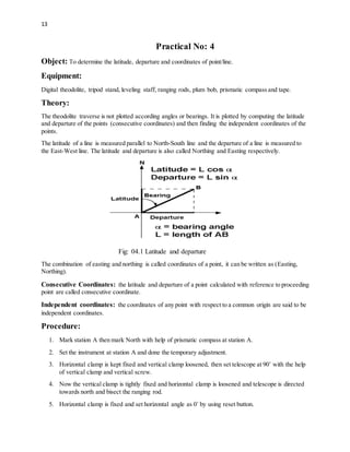
It is the total length of the curve from PC to PI.
11. Long Chord:
It is the chord joining PC to PT.
12. Mid Ordinate:
It is the distance or ordinate from the midpoint of the long chord to the midpoint of the curve.
13. Normal Chord:
A chord between two successive regular stations on a curve.
14. Sub-Chord:
It is any chord shorter than the normal chord.
Parameters or Elements of Simple Curve:
1. Length Of Curve:
L=⊼ R⏀/180˚
2. Deflection Angle:
⏀=180◦-I
3. Radius:
R=1719/D D=Degree of curve
4. Tangent Length:
T=R x tan (⏀/2)
5. Length Of Long Chord:
LC=2RSin (⏀/2)
6. Apex Distance:
E=R Sec [(⏀/2)-1]
7. Mid Ordinate:
M=R [1- Cos (⏀/2)]
8. Chainages:
Chainage of first tangent point (PC) = Chainage of intersection point (PI) – back tangent( T1)
Chainage of second tangent point (PT) = Chainage of first tangent point + curve length.](https://image.slidesharecdn.com/surveying-iiprfinalbytalha-190817191524/85/Surveying-practical-work-book-41-320.jpg)


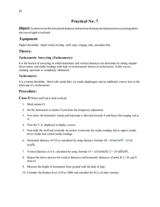
The document provides an overview of digital theodolites, detailing their functions, types, and components, including the telescope, targetor sight, and tripod, which are essential for measuring angles and distances in surveying. It outlines procedures for setting up and adjusting the theodolite for accurate readings, as well as methods for measuring vertical and horizontal angles and calculating coordinates and areas using the coordinate method. The document serves as a comprehensive guide for using digital theodolites in surveying practices.


