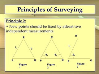
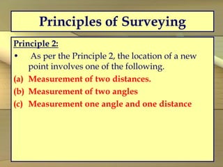
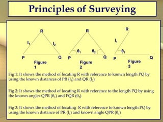
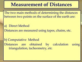
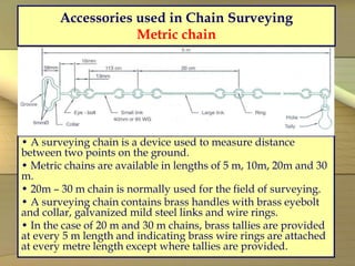
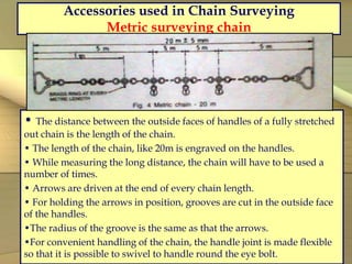
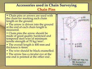
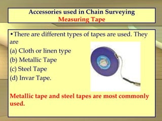
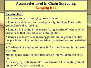
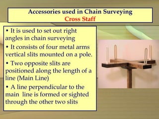
Edm is a surveying instrument used to measure the distance electronically. This Surveying Instrument is used in triangulation to measure the length of Base line because more accuracy is required to measure the length of base line.
This Presentation Contains Railway engineering concepts. The contents covered are Permanent way: Requirement, its component. Feel free to write in Comment Section or drop a line in my Inbox amanbathla710@gmail.com.
Principal of planning is basic need for planning of any type of building. It gives basic understanding for planning any type of building or building component.
What is a Total Station?
Capability of a Total Station
Important Operations of Total Station
Uses of Total Station
Advantages of Using Total Stations
Applications
About Subsurface investigation, Depth of foundation, Significant depth, Types of investigation, Steps involved, Methods of boring, Types of samples and samplers, Core recovery and RQD.
Surveying and scale_Surveying, Civil EngineeringA Makwana
It is defined as the process of measuring horizontal distances, vertical distances and included angles to determine the location of points on, above or below the earth surfaces.
The term surveying is the representation of surface features in a horizontal plane.
The process of determining the relative heights in the vertical plane is referred as levelling.
unit I
Introduction and Basic Concepts: Introduction, Objectives, classification and principles of
surveying, Scales, Shrinkage of Map, Conventional symbols and Code of Signals, Surveying
accessories, phases of surveying.
Measurement of Distances and Directions
Linear distances- Approximate methods, Direct Methods- Chains- Tapes, ranging, Tape corrections.
Prismatic Compass- Bearings, included angles, Local Attraction, Magnetic Declination and dip.
Distance Measurement & Chain Surveying
Contents
• Introduction About Surveying
.
• Primary Division Of Surveying • Classification Of Surveying • Distance Measurement And Chain Surveying • Principle Of Surveying • Types Of Tapes Based On The Materials Used • Erecting And Dropping A Perpendicular • Obstacle In Chain Survey • Types Of Errors • Corrections of Tape • Off –Sets • Ranging • Conclusion . • Homework And Next Lecture . • References.
-Definition of Surveying.
Types of Surveying
1. Plane Surveying
2. Geodetic Survey
3. Cadastral surveying
4. Aerial Surveying
5. Hydro graphic Surveying (Hydro-Survey)
6. Topographical Survey
7. Engineering Survey.
Primary division of Surveying
Reconnaissance.
• This is preliminary survey of the land to be surveyed. It may be either
1-Ground reconnaissance 2- Aerial reconnaissance survey.
Objectives of Reconnaissance
1. To ascertain the possibility of building or constructing route or track through the area.
Classification of Surveying:
1- Classification based on the instruments used:
A. Chain Surveying.
B. Compass Surveying.
C. Theodolite Surveying.
D. Tachometric Surveying .
E. Trigonometric Surveying.
F. Total station and GPS.
G. Photogrammetric and Aerial Surveying.
H. Plan Table .
2- According to the method used:
i. Traversing .
ii. Triangulation .
iii. Tacheometric.
iv. Trigonometric.
3- According to the Purpose of surveying:
i. Engineering survey.
ii. Military survey.
iii. Geological survey .
iv. Topographical survey
Chain and Tape Survey
-Length& Distance Measurements.
-Distance Measurement and Chain Surveying.
• In general there are two methods:
1- Direct methods of measuring lengths
2- Indirect methods of measuring distances.
There are two kinds of measurements used in plane surveying.
*Linear measurements
*Angular measurements
-Instruments used in Chain Surveying.
Types of tapes based on the materials used.
.......
.
.
.
.
.
.
.
.
.
.
Asst. Prof. Salar K.Hussein
Mr. Kamal Y.Abdullah
Asst.Lecturer. Dilveen H. Omar
Erbil Polytechnic University
Technical Engineering College
Civil Engineering Department
Sachpazis:Terzaghi Bearing Capacity Estimation in simple terms with Calculati...Dr.Costas Sachpazis
Terzaghi's soil bearing capacity theory, developed by Karl Terzaghi, is a fundamental principle in geotechnical engineering used to determine the bearing capacity of shallow foundations. This theory provides a method to calculate the ultimate bearing capacity of soil, which is the maximum load per unit area that the soil can support without undergoing shear failure. The Calculation HTML Code included.
TECHNICAL TRAINING MANUAL GENERAL FAMILIARIZATION COURSEDuvanRamosGarzon1
AIRCRAFT GENERAL
The Single Aisle is the most advanced family aircraft in service today, with fly-by-wire flight controls.
The A318, A319, A320 and A321 are twin-engine subsonic medium range aircraft.
The family offers a choice of engines
Quality defects in TMT Bars, Possible causes and Potential Solutions.PrashantGoswami42
Maintaining high-quality standards in the production of TMT bars is crucial for ensuring structural integrity in construction. Addressing common defects through careful monitoring, standardized processes, and advanced technology can significantly improve the quality of TMT bars. Continuous training and adherence to quality control measures will also play a pivotal role in minimizing these defects.
CFD Simulation of By-pass Flow in a HRSG module by R&R Consult.pptxR&R Consult
CFD analysis is incredibly effective at solving mysteries and improving the performance of complex systems!
Here's a great example: At a large natural gas-fired power plant, where they use waste heat to generate steam and energy, they were puzzled that their boiler wasn't producing as much steam as expected.
R&R and Tetra Engineering Group Inc. were asked to solve the issue with reduced steam production.
An inspection had shown that a significant amount of hot flue gas was bypassing the boiler tubes, where the heat was supposed to be transferred.
R&R Consult conducted a CFD analysis, which revealed that 6.3% of the flue gas was bypassing the boiler tubes without transferring heat. The analysis also showed that the flue gas was instead being directed along the sides of the boiler and between the modules that were supposed to capture the heat. This was the cause of the reduced performance.
Based on our results, Tetra Engineering installed covering plates to reduce the bypass flow. This improved the boiler's performance and increased electricity production.
It is always satisfying when we can help solve complex challenges like this. Do your systems also need a check-up or optimization? Give us a call!
Work done in cooperation with James Malloy and David Moelling from Tetra Engineering.
More examples of our work https://www.r-r-consult.dk/en/cases-en/
Hybrid optimization of pumped hydro system and solar- Engr. Abdul-Azeez.pdffxintegritypublishin
Advancements in technology unveil a myriad of electrical and electronic breakthroughs geared towards efficiently harnessing limited resources to meet human energy demands. The optimization of hybrid solar PV panels and pumped hydro energy supply systems plays a pivotal role in utilizing natural resources effectively. This initiative not only benefits humanity but also fosters environmental sustainability. The study investigated the design optimization of these hybrid systems, focusing on understanding solar radiation patterns, identifying geographical influences on solar radiation, formulating a mathematical model for system optimization, and determining the optimal configuration of PV panels and pumped hydro storage. Through a comparative analysis approach and eight weeks of data collection, the study addressed key research questions related to solar radiation patterns and optimal system design. The findings highlighted regions with heightened solar radiation levels, showcasing substantial potential for power generation and emphasizing the system's efficiency. Optimizing system design significantly boosted power generation, promoted renewable energy utilization, and enhanced energy storage capacity. The study underscored the benefits of optimizing hybrid solar PV panels and pumped hydro energy supply systems for sustainable energy usage. Optimizing the design of solar PV panels and pumped hydro energy supply systems as examined across diverse climatic conditions in a developing country, not only enhances power generation but also improves the integration of renewable energy sources and boosts energy storage capacities, particularly beneficial for less economically prosperous regions. Additionally, the study provides valuable insights for advancing energy research in economically viable areas. Recommendations included conducting site-specific assessments, utilizing advanced modeling tools, implementing regular maintenance protocols, and enhancing communication among system components.
Welcome to WIPAC Monthly the magazine brought to you by the LinkedIn Group Water Industry Process Automation & Control.
In this month's edition, along with this month's industry news to celebrate the 13 years since the group was created we have articles including
A case study of the used of Advanced Process Control at the Wastewater Treatment works at Lleida in Spain
A look back on an article on smart wastewater networks in order to see how the industry has measured up in the interim around the adoption of Digital Transformation in the Water Industry.
Forklift Classes Overview by Intella PartsIntella Parts
Discover the different forklift classes and their specific applications. Learn how to choose the right forklift for your needs to ensure safety, efficiency, and compliance in your operations.
For more technical information, visit our website https://intellaparts.com
Final project report on grocery store management system..pdfKamal Acharya
In today’s fast-changing business environment, it’s extremely important to be able to respond to client needs in the most effective and timely manner. If your customers wish to see your business online and have instant access to your products or services.
Online Grocery Store is an e-commerce website, which retails various grocery products. This project allows viewing various products available enables registered users to purchase desired products instantly using Paytm, UPI payment processor (Instant Pay) and also can place order by using Cash on Delivery (Pay Later) option. This project provides an easy access to Administrators and Managers to view orders placed using Pay Later and Instant Pay options.
In order to develop an e-commerce website, a number of Technologies must be studied and understood. These include multi-tiered architecture, server and client-side scripting techniques, implementation technologies, programming language (such as PHP, HTML, CSS, JavaScript) and MySQL relational databases. This is a project with the objective to develop a basic website where a consumer is provided with a shopping cart website and also to know about the technologies used to develop such a website.
This document will discuss each of the underlying technologies to create and implement an e- commerce website.
Democratizing Fuzzing at Scale by Abhishek Aryaabh.arya
Presented at NUS: Fuzzing and Software Security Summer School 2024
This keynote talks about the democratization of fuzzing at scale, highlighting the collaboration between open source communities, academia, and industry to advance the field of fuzzing. It delves into the history of fuzzing, the development of scalable fuzzing platforms, and the empowerment of community-driven research. The talk will further discuss recent advancements leveraging AI/ML and offer insights into the future evolution of the fuzzing landscape.
COLLEGE BUS MANAGEMENT SYSTEM PROJECT REPORT.pdfKamal Acharya
The College Bus Management system is completely developed by Visual Basic .NET Version. The application is connect with most secured database language MS SQL Server. The application is develop by using best combination of front-end and back-end languages. The application is totally design like flat user interface. This flat user interface is more attractive user interface in 2017. The application is gives more important to the system functionality. The application is to manage the student’s details, driver’s details, bus details, bus route details, bus fees details and more. The application has only one unit for admin. The admin can manage the entire application. The admin can login into the application by using username and password of the admin. The application is develop for big and small colleges. It is more user friendly for non-computer person. Even they can easily learn how to manage the application within hours. The application is more secure by the admin. The system will give an effective output for the VB.Net and SQL Server given as input to the system. The compiled java program given as input to the system, after scanning the program will generate different reports. The application generates the report for users. The admin can view and download the report of the data. The application deliver the excel format reports. Because, excel formatted reports is very easy to understand the income and expense of the college bus. This application is mainly develop for windows operating system users. In 2017, 73% of people enterprises are using windows operating system. So the application will easily install for all the windows operating system users. The application-developed size is very low. The application consumes very low space in disk. Therefore, the user can allocate very minimum local disk space for this application.
Student information management system project report ii.pdfKamal Acharya
Our project explains about the student management. This project mainly explains the various actions related to student details. This project shows some ease in adding, editing and deleting the student details. It also provides a less time consuming process for viewing, adding, editing and deleting the marks of the students.
2. Surveying
•It is defined as the process of measuring
horizontal distances, vertical distances and
included angles to determine the location of points
on, above or below the earth surfaces.
• The term surveying is the representation of
surface features in a horizontal plane.
• The process of determining the relative heights in
the vertical plane is referred as leveling.
3. Objectives of Surveying
• The data obtained by surveying are used to prepare the
plan or map showing the ground features.
• When the area surveyed is small and the scale to which
its result plotted is large, then it is known as Plan
• When the area surveyed is large and the scale to which
its result plotted is small, then it is called as a Map
•Setting out of any engineering work like buildings, roads,
railway tracks, bridges and dams involves surveying.
4. Main divisions of surveying
Concept:
• Since the shape of the earth is spheroidal, the
line connecting any two points on the earth
surface is not a straight line, but a curve.
• When the surveys extend over a large areas or
when the accuracy required is great, the curvature
of earth has also to be taken into account.
Types of Surveying
•Plane surveying
• Geodetic surveying
5. Plane Surveying
• The surveying where the effect of curvature of
earth is neglected and earth’s surface is treated as
plane, is called plane surveying.
• The degree of accuracy in this type of surveying
is comparatively low.
• Generally when the surveying is conducted over
the area less than 260 Sq.Km., they are treated as
plane surveying.
• Plane surveying is conducted for the purpose of
engineering projects.
6. Geodetic Surveying
• The effect of curvature is taken into account.
• It is also known as “Trigonometrical Surveying”.
• It is a special branch of surveying in which
measurements are taken with high precision
instruments.
• Calculations are also made with help of spherical
trigonometry.
• It is generally adopted by the Great
Trigonometrical Survey Department of India”.
(GTS).
7. Classification of surveying
Depending on the use and the purpose of the
resulting maps, surveys are
1. Classification Based upon the Nature of the
Field Survey
Land Surveying
Marine or Navigation or Hydrographic
Surveying
Astronomical Survey
2. Classification Based on the Object of Survey
Engineering Surveys
8. Classification of surveying
Military Surveys
Mine Surveys
Geological Surveys
Archaeological Surveys
3. Classification Based on Instruments Used
Chain surveying , Theodolite surveying ,Traverse
surveying ,Triangulation surveying ,Tachometric
surveying , Plane table surveying , hotographic
surveying ,Aerial surveying ,Compass surveying
9. Classification of surveying
Land Surveying: Land survey is a one, in which the relative
points or objects on the earth’s surface is determined.
10. Classification of surveying
Marine or Navigational or Hydrographic Survey:
Marine surveying is one in which in which the relative
position of objects under water is determined.
12. Classification of Land surveying
Topographical Survey:
• It is used for determining the natural and artificial
features of the country such as rivers, lakes, hills and canals.
13. Principles of Surveying
Principle 1:
• A number of control points are fixed in the area
concerned by adopting very accurate and precise
methods.
• The lines joining these control points will be
control lines.
• Other measurements are made to locate points
inside these control lines.
• Thus, main triangles and traverses are formed
first.
14. Principles of Surveying
Principle 1:
• The main triangles and traverses are divided into
smaller ones by using less rigorous methods.
• By doing so, accumulation of errors is avoided
and any local error can be easily identified.
• If survey work is started from a part (smaller
triangle or traverse) and proceeded to whole there
are chances of errors getting multiplied at every
stage.
• Hence any survey work should be from whole
to part and not from part to whole.
15. Principles of Surveying
Principle 2:
• New points should be fixed by atleast two
independent measurements.
l1 l2
P Q
R
Figure
1
P Q
R
θ1 θ2
Figure
2
P Q
R
θ1
Figure
3
l1
16. Principles of Surveying
Principle 2:
• As per the Principle 2, the location of a new
point involves one of the following.
(a) Measurement of two distances.
(b) Measurement of two angles
(c) Measurement one angle and one distance
17. Principles of Surveying
Fig 1: It shows the method of locating R with reference to known length PQ by
using the known distances of PR (l1) and QR (l2)
Fig 2: It shows the method of locating R with reference to the length PQ by using
the known angles QPR (θ1) and PQR (θ2)
Fig 3: It shows the method of locating R with reference to known length PQ by
using the known distance of PR (l1) and known angle QPR (θ1)
l1 l2
P Q
R
Figure
1
P Q
R
θ1 θ2
Figure
2
P Q
R
θ1
Figure
3
l1
18. Measurement of Distances
The two main methods of determining the distances
between two points on the surface of the earth are:
a) Direct Method
Distances are measured using tapes, chains, etc.
b) Computative Method
Distances are obtained by calculation using
triangulation, tacheometry, etc.
19. Chain Surveying - Principle
• In chain surveying only linear distances on the
field are measured.
• These distances are used to define the boundary
of field and mark simple details.
Principle :
• It is to form a network of triangles by using the
distances measured.
• Better accuracy will be obtained if the triangles
thus formed are nearly equilateral in shape.
20. Accessories used in Chain Surveying
The different accessories used in chain surveying
are
(a) Metric Chain
(b) Chain Pins (arrows)
(c) Measuring Tape
(d) Ranging rod/Offset rod
(e) Cross staff
21. Accessories used in Chain Surveying
Metric chain
• A surveying chain is a device used to measure distance
between two points on the ground.
• Metric chains are available in lengths of 5 m, 10m, 20m and 30
m.
• 20m – 30 m chain is normally used for the field of surveying.
• A surveying chain contains brass handles with brass eyebolt
and collar, galvanized mild steel links and wire rings.
• In the case of 20 m and 30 m chains, brass tallies are provided
at every 5 m length and indicating brass wire rings are attached
at every metre length except where tallies are provided.
22. Accessories used in Chain Surveying
Metric surveying chain
• The distance between the outside faces of handles of a fully stretched
out chain is the length of the chain.
• The length of the chain, like 20m is engraved on the handles.
• While measuring the long distance, the chain will have to be used a
number of times.
• Arrows are driven at the end of every chain length.
• For holding the arrows in position, grooves are cut in the outside face
of the handles.
•The radius of the groove is the same as that the arrows.
•For convenient handling of the chain, the handle joint is made flexible
so that it is possible to swivel to handle round the eye bolt.
23. Accessories used in Chain Surveying
Chain Pins
• Chain pins or arrows are used with
the chain for marking each chain
length on the ground.
• The arrow is driven into the ground
at the end of each chain length is
measured.
• Chain pins the arrow should be
made of good quality hardened and
tempered steel wire of minimum
tensile strength of 70 kg/mm2.
• The overall length is 400 mm and
thickness is 4mm.
• The wire should be black enamelled.
• The arrow has a circular eye at the
one end is pointed at the other end .
24. Accessories used in Chain Surveying
Measuring Tape
•There are different types of tapes are used. They
are
(a) Cloth or linen type
(b) Metallic Tape
(c) Steel Tape
(d) Invar Tape.
Metallic tape and steel tapes are most commonly
used.
25. Accessories used in Chain Surveying
Ranging Rod
Ranging Rod:
• It is also known as ranging pole or picket.
• Ranging rod is used for ranging or aligning long lines on the
ground in field surveying.
• Ranging is a straight line means fixing a series of pegs or other
marks such that they all lie on a straight line.
• Ranging rods are used marking points on the ground so that
the positions of the points are distinctly visible from some distant
way.
• The length of ranging rod may be 2 m and 3 m and its diameter
is 30 mm.
•Ranging rod made of steel tube has an internal diameter of 32
mm.
• The ranging rods are made of well seasoned, straight grained
timber of circular cross section.
26. Accessories used in Chain Surveying
Ranging Rod
•Ranging rods should be
straight and free from warps.
• The deviation in
straightness should not exceed
5mm in a 2 m length.
• The ranging rod is painted
in red and white in alternate
band lengths of 200 mm each.
• The bottom end of the rod is
fitted with a pointed, hollow,
cast iron shoe or steel shoe of
15 cm length.
27. Accessories used in Chain Surveying
Cross Staff
• It is used to set out right
angles in chain surveying
• It consists of four metal arms
vertical slits mounted on a pole.
• Two opposite slits are
positioned along the length of a
line (Main Line)
• A line perpendicular to the
main line is formed or sighted
through the other two slits
28. Advantages and disadvantages of
chain surveying
Advantages:
•It is simple
• It does not require any costly equipment
• It is adopted for preparing plans for small area
Disadvantages:
• It cannot be used for large areas
• It cannot be used in thick bushy areas with ups
and downs.
• Chain surveying is not always accurate.
29. Measurement of Angles
The instruments commonly used for measurement of angles are
(1) Compass (2) Theodolite and (3) Box sextant Ranging
Method of Measurement of Angles
The horizontal angles may be measured in two ways:
1. Included angles
31. Compass Surveying
• Whenever a number of base lines
are to be run for obtaining the
details as in traversing, just linear
measurements made by chain
surveying will not be sufficient.
• The angles included between the
adjacent lines should also be
measured
• Compass is one of the
instruments used to measure the
angles.
33. Prismatic Compass
Description:
• A magnetic needle is balanced over a pivot in a circular box of 85
mm to 110 mm in diameter.
• A graduated aluminium ring is attached to the magnetic needle.
• An agate cap keeps the aluminium ring stable.
• The box is covered by a glass lid.
• Object vane and eye vane are provided at diametrically opposite
ends.
• Eye vane caries a reflecting prism which can be raised or lowered as
desired.
• A vertical horse hair or fine wire is provided at the middle of the
object vane.
• The graduations in the aluminium ring are made in the clockwise
direction starting with 0o at South and 180o at North with inverted
markings.
34. Prismatic Compass
Description:
• A triangular prism fitted below the eye slit enables
magnification of readings to suit observer’s eye.
• Based on this prism arrangement, the compass is
named prismatic compass.
• Compass is fixed over a tripod with ball and socket
arrangement.
• A braked pin is provided below the object vane to
damp the oscillations of the magnetic needle while
taking readings.
35. Prismatic Compass
Working Principle:
• The magnetic field aligns itself with the magnetic meridian (N-S
direction)
• The line of sight is actually the line joining the object vane and eye
vane
• The angle between the N-S direction and the line of sight is
observed in the compass
• This angle is actually the angle between N-S direction and the line
on the ground
• This angle made by the line with the N-S direction is called the
bearing of the line.
• Compass is used to measure the bearing of the different lines from
which the angles included between the adjacent lines are computed.
36. How to take reading using compass
• The compass is centered over the station by dropping a small
piece of stone from the centre of the bottom of the compass.
•The compass is levelled by adjusting the ball and socket till the
top of the box is horizontal.
• The graduated ring should move freely after having levelled
the instrument.
• Suppose the bearing of a line PQ is to be observed.
• The compass is centered over P.
• It is levelled.
• The prism and the object vane are kept in vertical position.
• The compass is turned slowly till the ranging rod already
erected at Q is bisected.
37. How to take reading using compass
• In this position, the ranging rod, the object and
the eye vane all lie in the same line.
• The focusing prism is raised or lowered till the
readings were clear and sharp.
• The reading in the ring cut by the object hair line
is taken after damping the oscillations of the ring
by pressing the brake pin.
38. Levelling
•It is a surveying method used to determine the level of
points/objects with reference to the selected datum.
•It is also used to set out engineering works.
Uses of Levelling:
• To determine the difference in levels of points/Objects
• To obtain contour map of an area
• To obtain cross section of roads, canals etc.,
• To determine the depth cutting and filling in engineering
works.
• To establish points or erect machinery or construct a building
component at a predetermined level.
39. Important Terms
Bench Mark: It is surveyor’s mark cut on a stone/
rock or any reference point used to indicate a level
in a levelling survey.
Reduced Level:
•Reduced level of a point is the level of the point
with respect to the level of permanent feature or
bench mark.
• It indicates whether the point is above or below
the reference point.
40. Instruments used in levelling
Instruments used in levelling are,
(i)Levelling instrument
(ii)Levelling staff
Levelling Instrument :
• Simplest form of levelling instrument is dumpy
level.
• The different parts of levelling instrument are,
(a) Telescope (b) Eye-piece (c) focussing knob (d) level
tube (e) cross bubble (f) foot screws (g) levelling head
(h) diaphragm (i) ray shade
41. Thank You
Prepared by
S.Maniraj M.E., (Ph.D)
Assistant Professor,
Department of Mechanical Engineering, Paavai
Engineering College,
Namakkal.
maniraj4016@gmail.com