SURVEYING – I(CE- 128)
TRAVERSING
1
NUST Institute of Civil Engineering/Engr. Ahmed Rasheed Mirza
2.
SURVEYING – I(CE- 128)
2
A series of connected straight lines each joining two points on the ground, is called a
‘traverse’. End points are known as traverse stations & straight lines between two
consecutive stations, are called traverse legs.
A traverse survey is one in which the framework consists of a series of connected
lines, the lengths and directions of which are measured with a chain or a tape, and with
an angular instrument respectively.
Traverses may be either a closed traverse or an open traverse:
1. Closed Traverse: A traverse is said to be closed when a complete circuit is
made, i.e. when it returns to the starting point forming a closed polygon or when it begins
and ends at points whose positions on plan are known. The work may be checked and
“balanced”. It is particularly suitable for locating the boundaries of lakes, woods, etc.
and for the survey of moderately large areas.
2. Open Traverse: A traverse is said to be open or unclosed when it does not
form a closed polygon. It consists of a series of lines extending in the same general
direction and not returning to the starting point. Similarly, it does not start and end at the
points whose positions on plan are known. It is most suitable for the survey of a long
narrow strip of country e.g. the valley of a river, the coast line, a long meandering road,
or railway, etc.
NUST Institute of Civil Engineering/Engr. Ahmed Rasheed Mirza
3.
SURVEYING – I(CE- 128)
3
Classification of traverses based on instruments used:
1. Chain Traversing: In chain traversing, the entire work is done by a chain or tape
& no angular measuring instrument is needed. The angles computed by tie
measurements are known as chain angles.
2. Compass Traversing: The traverse in which angular measurements are made
with a surveying compass, is known as compass traversing. The traverse angle
between two consecutive legs is computed by observing the bearings of the sides.
3. Plane Table Traversing: The traverse in which angular measurements between
the traverse sides are plotted graphically on a plane table with the help of an
alidade is known as plane table traversing.
4. Theodolite Traversing: The traverse in which angular measurements between
traverse sides are made with a theodolite is known as theodolite traversing.
5. Tachometric Traversing: The traverse in which direct measurements of
traverse sides by chaining is dispensed with & these are obtained by making
observations with a tachometer is known as tachometer traversing.
NUST Institute of Civil Engineering/Engr. Ahmed Rasheed Mirza
4.
SURVEYING – I(CE- 128)
4
Important Technical Terms:
1. Meridians and Bearings: The direction of survey lines may be defined in two ways:
a). Relatively to each other
b). Relatively to some reference direction
In the first case, directions are expressed in terms of the angles between two
consecutive lines. In second case, these are expressed in terms of bearings.
The fixed direction on the surface of the earth with reference to which, bearings
of survey lines are expressed is called a meridian. The meridians of reference directions
employed in surveying may be one of the following:
a). True Meridian b). Magnetic Meridian
c). Grid Meridian* d). Arbitrary Meridian
o The line of intersection of the earth surface by a plane containing north pole, south
pole and the given place is called true meridian or geographical meridian.
oThe geometrical longitudinal axis of a freely suspended & properly balanced magnetic
needle, unaffected by local attractive forces, defines the magnetic north-south line which
is called the magnetic meridian.
o The convenient direction assumed as meridian for measuring bearings of survey lines
is known as arbitrary meridian.
NUST Institute of Civil Engineering/Engr. Ahmed Rasheed Mirza
5.
SURVEYING – I(CE- 128)
5
The horizontal angle between the reference meridian and the survey line
measured in a clockwise direction is called bearing.
a). True Bearing b). Azimuth
c). Magnetic Bearing d). Grid Bearing
o The horizontal angle between the true meridian and a line measured in a clockwise
direction is called true bearing of the line.
o The smaller angle which a survey line makes with true meridian is called azimuth.
oThe horizontal angle which a line makes with the magnetic meridian is called magnetic
bearing.
o Bearings of survey lines referred to and reckoned from grid lines are called grid
bearings.
o The angle between the true meridian & the magnetic meridian at any place is known
as magnetic declination, whereas, the angle between the true meridian & the grid
meridian at any place is known as grid convergence.
NUST Institute of Civil Engineering/Engr. Ahmed Rasheed Mirza
6.
SURVEYING – I(CE- 128)
6
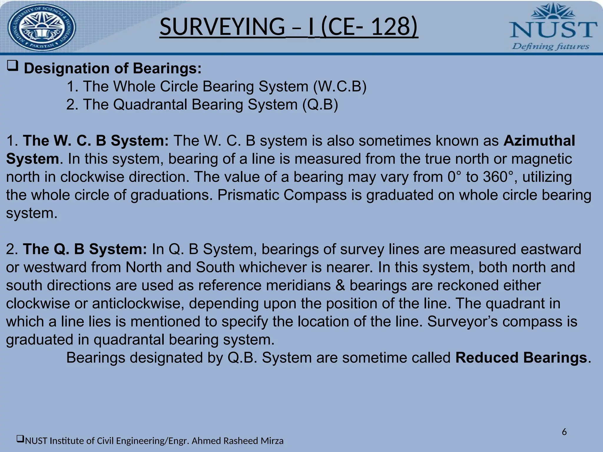
Designation of Bearings:
1. The Whole Circle Bearing System (W.C.B)
2. The Quadrantal Bearing System (Q.B)
1. The W. C. B System: The W. C. B system is also sometimes known as Azimuthal
System. In this system, bearing of a line is measured from the true north or magnetic
north in clockwise direction. The value of a bearing may vary from 0° to 360°, utilizing
the whole circle of graduations. Prismatic Compass is graduated on whole circle bearing
system.
2. The Q. B System: In Q. B System, bearings of survey lines are measured eastward
or westward from North and South whichever is nearer. In this system, both north and
south directions are used as reference meridians & bearings are reckoned either
clockwise or anticlockwise, depending upon the position of the line. The quadrant in
which a line lies is mentioned to specify the location of the line. Surveyor’s compass is
graduated in quadrantal bearing system.
Bearings designated by Q.B. System are sometime called Reduced Bearings.
NUST Institute of Civil Engineering/Engr. Ahmed Rasheed Mirza
7.
7
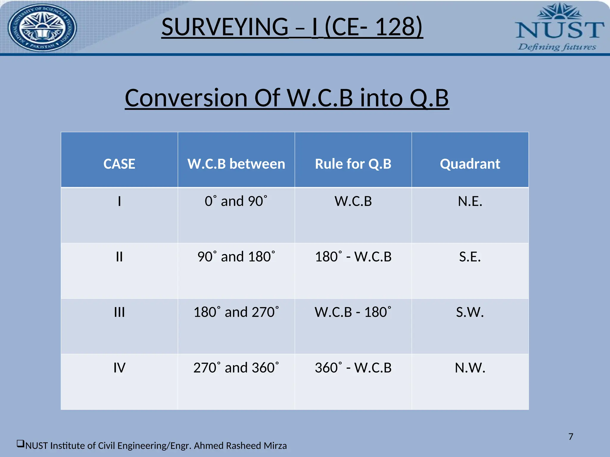
CASE W.C.B betweenRule for Q.B Quadrant
I 0˚ and 90˚ W.C.B N.E.
II 90˚ and 180˚ 180˚ - W.C.B S.E.
III 180˚ and 270˚ W.C.B - 180˚ S.W.
IV 270˚ and 360˚ 360˚ - W.C.B N.W.
Conversion Of W.C.B into Q.B
SURVEYING – I (CE- 128)
NUST Institute of Civil Engineering/Engr. Ahmed Rasheed Mirza
8.
8
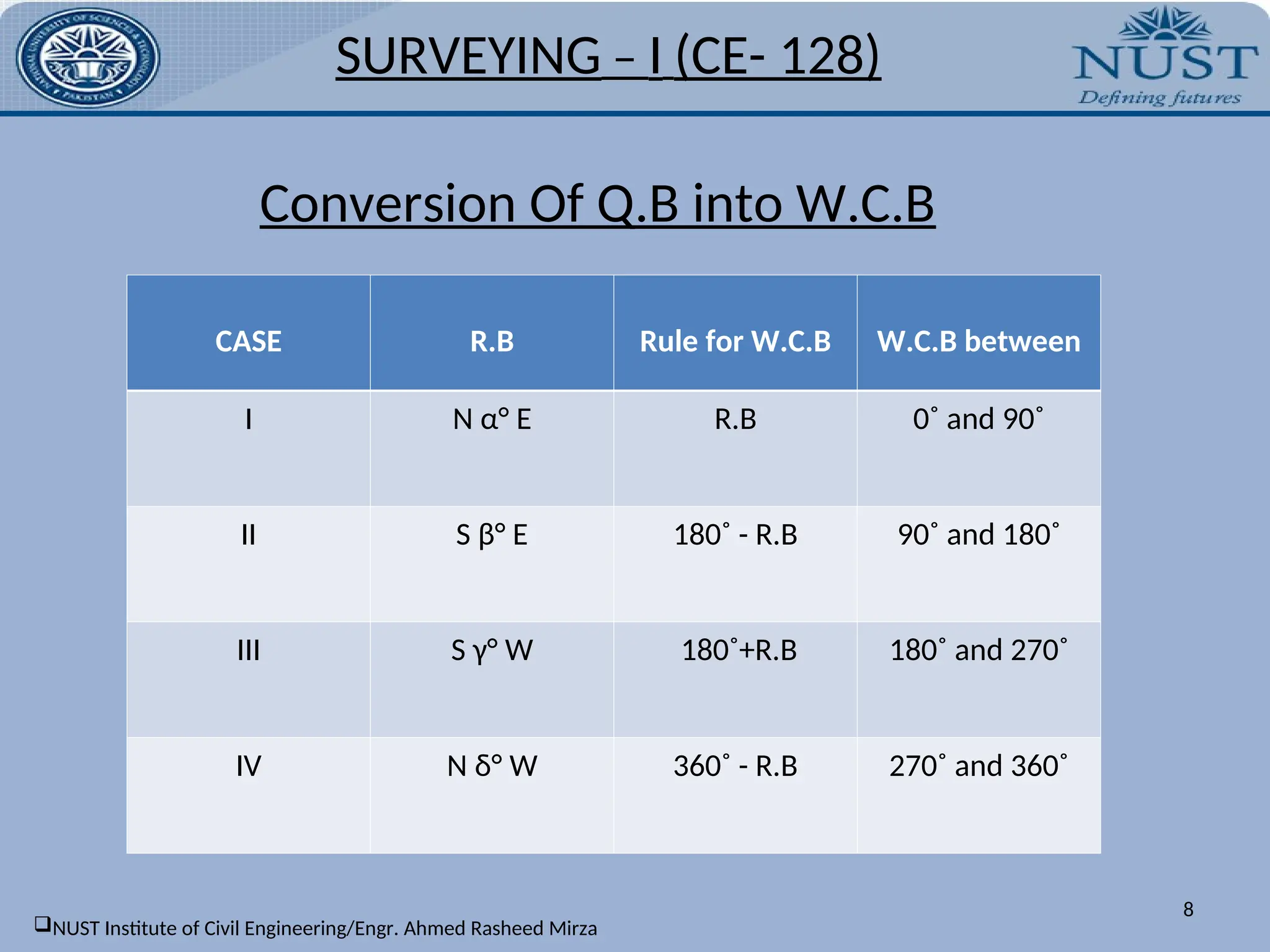
CASE R.B Rulefor W.C.B W.C.B between
I N α° E R.B 0˚ and 90˚
II S β° E 180˚ - R.B 90˚ and 180˚
III S γ° W 180˚+R.B 180˚ and 270˚
IV N δ° W 360˚ - R.B 270˚ and 360˚
Conversion Of Q.B into W.C.B
SURVEYING – I (CE- 128)
NUST Institute of Civil Engineering/Engr. Ahmed Rasheed Mirza
9.
SURVEYING – I(CE- 128)
9
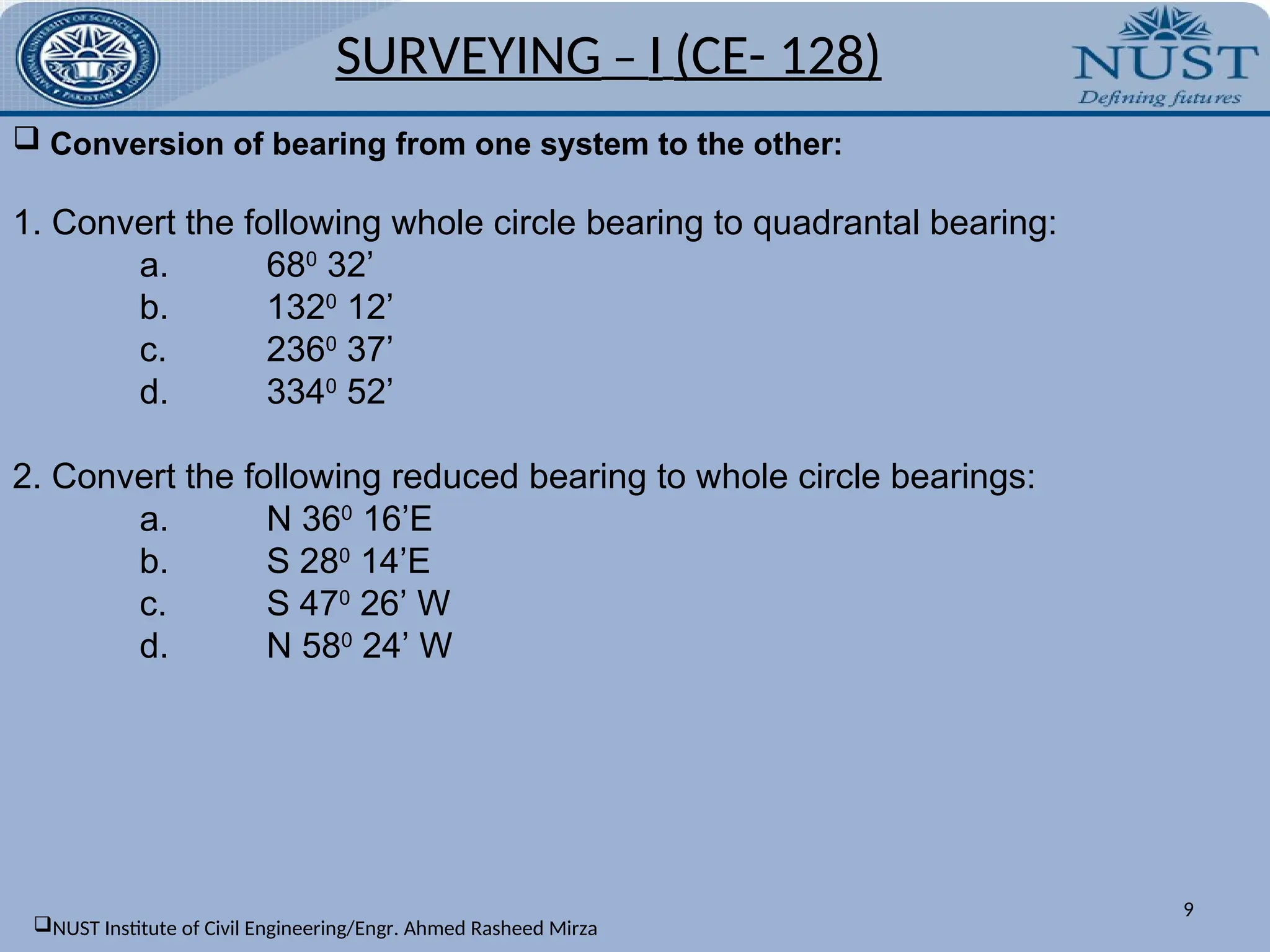
Conversion of bearing from one system to the other:
1. Convert the following whole circle bearing to quadrantal bearing:
a. 680
32’
b. 1320
12’
c. 2360
37’
d. 3340
52’
2. Convert the following reduced bearing to whole circle bearings:
a. N 360
16’E
b. S 280
14’E
c. S 470
26’ W
d. N 580
24’ W
NUST Institute of Civil Engineering/Engr. Ahmed Rasheed Mirza
10.
10
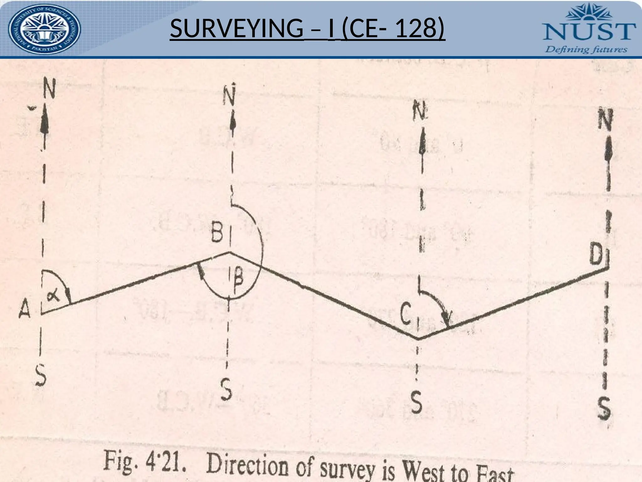
FORE andBACK Bearings:
Every line may be defined by two bearings, one observed at either end
of the line. Both the bearings expressed in W.C.B System differ each other by 180°. The
bearing of a line in the direction of the progress of survey, is called Fore or Forward
Bearing (F.B) while the bearing in the opposite direction of the progress of survey is
known as Reverse or Back Bearing (B.B).
Relationship Between Fore and Back Bearings:
a). W.C.B System:
Back bearing = Fore Bearing + 180˚
Positive sign is used when fore bearing is less than 180˚ and negative sign is used
when the fore bearing is greater than 180˚.
b). Q.B System:
To convert the fore bearing of a line into its back bearing
in Q.B system, replace N by S, S by N, E by W and W by E , without changing the
numerical value of the bearing.
SURVEYING – I (CE- 128)
NUST Institute of Civil Engineering/Engr. Ahmed Rasheed Mirza
12
1. The followingare the observed fore bearing of the lines:
a. AB, 380
14’ ; BC, 1420
18’ ; CD, 2080
37’ and DE, 3180
26’
b. Find their back bearings.
2. The fore bearings of the lines are as follows:
a. AB: N 320
12’ E; BC: S 430
18 E; CD: S 260
30’ W; DE: N 650
24’ W.
b. Find their back bearings
SURVEYING – I (CE- 128)
NUST Institute of Civil Engineering/Engr. Ahmed Rasheed Mirza
13.
13
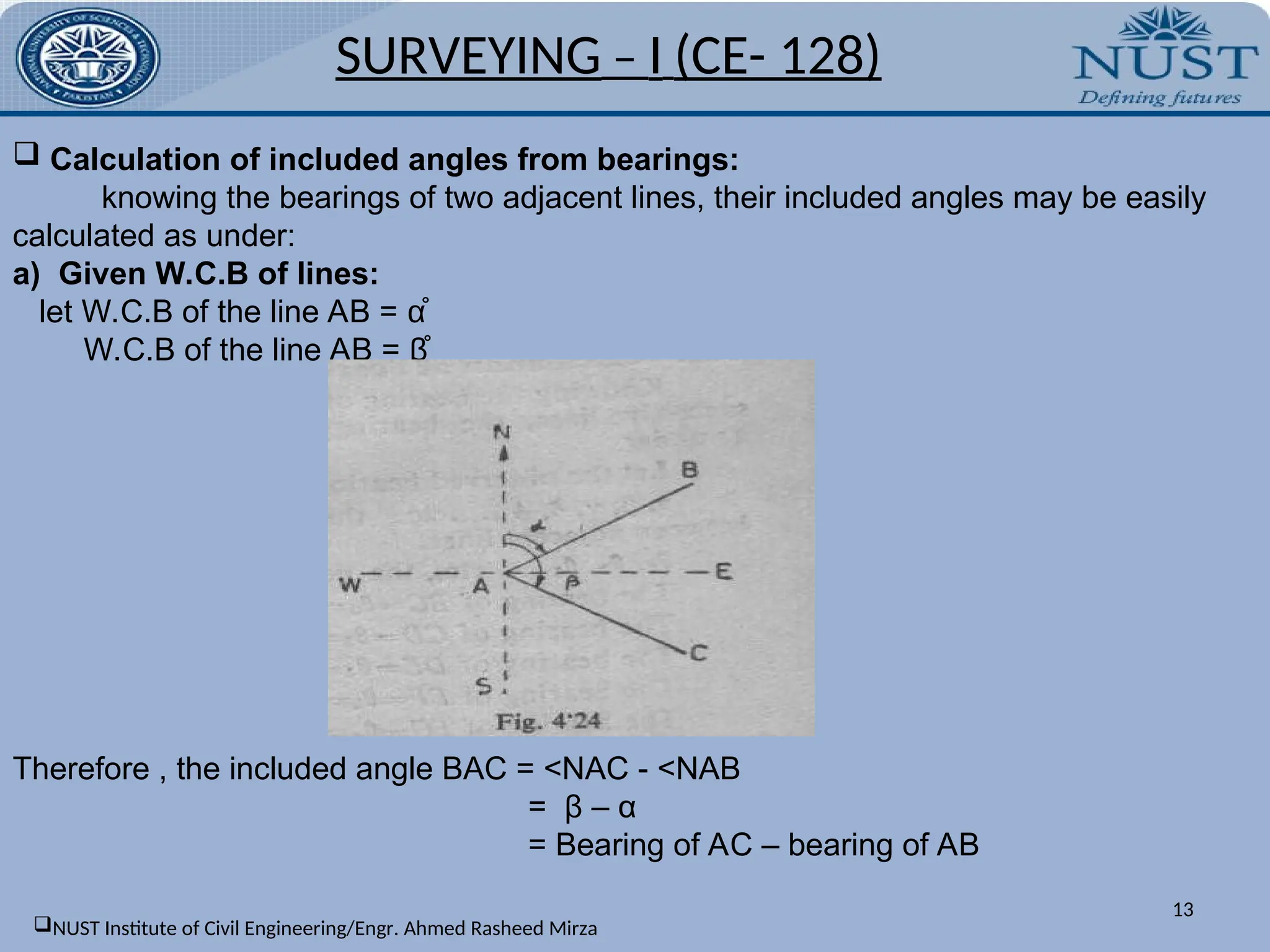
Calculation ofincluded angles from bearings:
knowing the bearings of two adjacent lines, their included angles may be easily
calculated as under:
a) Given W.C.B of lines:
let W.C.B of the line AB = α̊
W.C.B of the line AB = β̊
Therefore , the included angle BAC = <NAC - <NAB
= β – α
= Bearing of AC – bearing of AB
SURVEYING – I (CE- 128)
NUST Institute of Civil Engineering/Engr. Ahmed Rasheed Mirza
14.
14
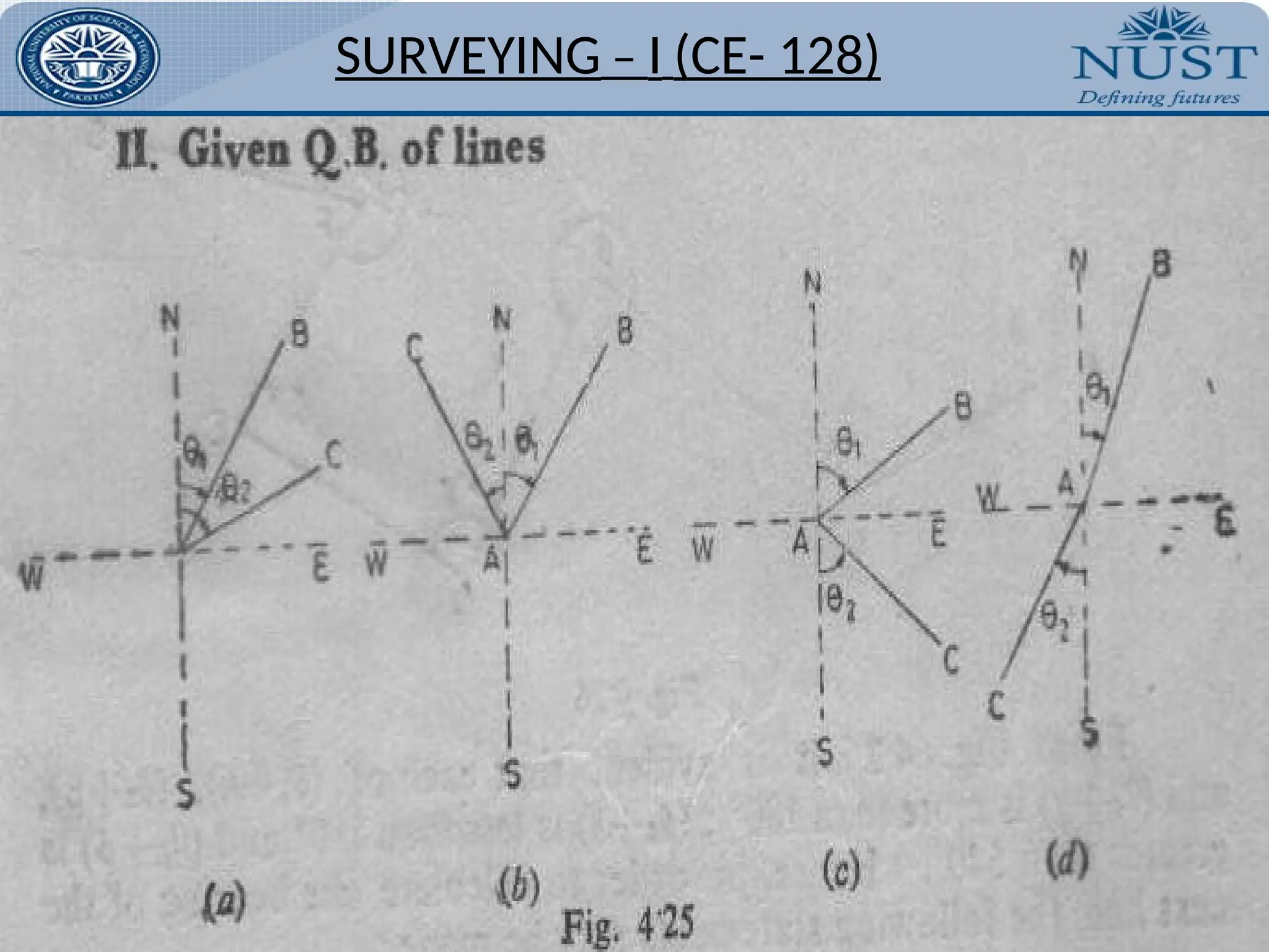
b) Given Q.Bof lines:
A diagram may be drawn and bearings of the lines plotted in their respective quadrants.
The included angle is calculated from one of the under mentioned formulae:
1) If the bearings have been measured to the same side of the common meridian, the
included angle α = θ2 – θ1 i.e. the difference of the bearings. This is true for all
quadrants.[fig 4.25 a]
2) If the bearings have been measured to the opposite side of the common meridian,
the included angle α = θ1 + θ2 i.e. the sum of the bearings. [fig 4.25 b]
3) If the bearings have been measured to the same side of the different meridians, the
included angle α = 180˚ - (θ1 + θ2) i.e. the difference of 180 and the sum of the
bearings. [fig 4.25 c]
4) If the bearings have been measured to the opposite side of the different meridians,
the included angle α = 180˚ - (θ1 - θ2) i.e. the difference of 180 and the difference of
the bearings. [fig 4.25 d]
SURVEYING – I (CE- 128)
NUST Institute of Civil Engineering/Engr. Ahmed Rasheed Mirza
16
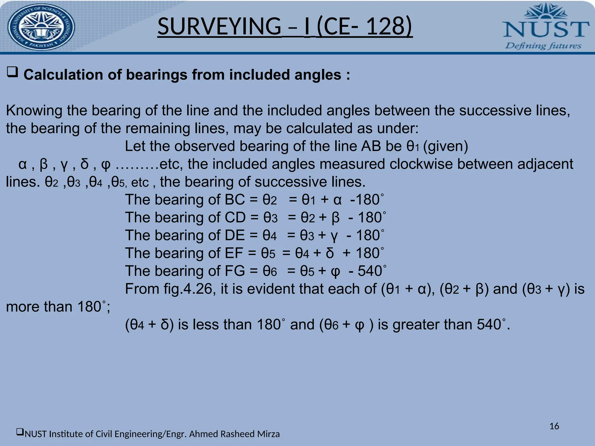
Calculation ofbearings from included angles :
Knowing the bearing of the line and the included angles between the successive lines,
the bearing of the remaining lines, may be calculated as under:
Let the observed bearing of the line AB be θ1 (given)
α , β , γ , δ , φ ………etc, the included angles measured clockwise between adjacent
lines. θ2 ,θ3 ,θ4 ,θ5, etc , the bearing of successive lines.
The bearing of BC = θ2 = θ1 + α -180˚
The bearing of CD = θ3 = θ2 + β - 180˚
The bearing of DE = θ4 = θ3 + γ - 180˚
The bearing of EF = θ5 = θ4 + δ + 180˚
The bearing of FG = θ6 = θ5 + φ - 540˚
From fig.4.26, it is evident that each of (θ1 + α), (θ2 + β) and (θ3 + γ) is
more than 180˚;
(θ4 + δ) is less than 180˚ and (θ6 + φ ) is greater than 540˚.
SURVEYING – I (CE- 128)
NUST Institute of Civil Engineering/Engr. Ahmed Rasheed Mirza
17.
Hence, in orderto calculate the bearing of the next line, the following statements may be
made:
“Add the included angle measured clockwise to the bearing of the previous line.
If the sum is:
more than 180˚,deduct 180˚
more than 540˚,deduct 540˚
less than 180˚,add 180˚,to get the bearing of the next line.”
SURVEYING – I (CE- 128)
17
NUST Institute of Civil Engineering/Engr. Ahmed Rasheed Mirza
18.
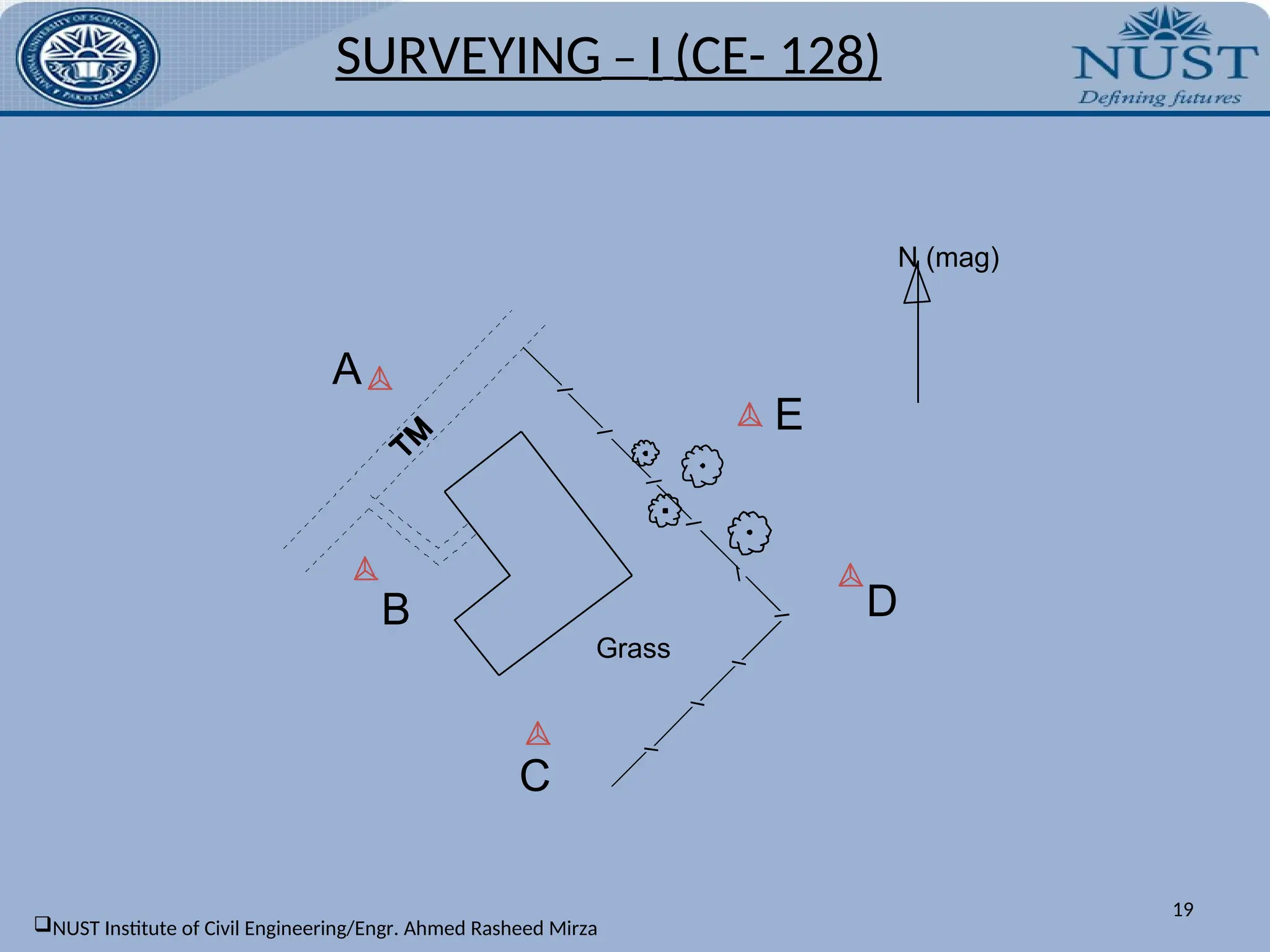
TRAVERSE EXAMPLE:
SURVEYING– I (CE- 128)
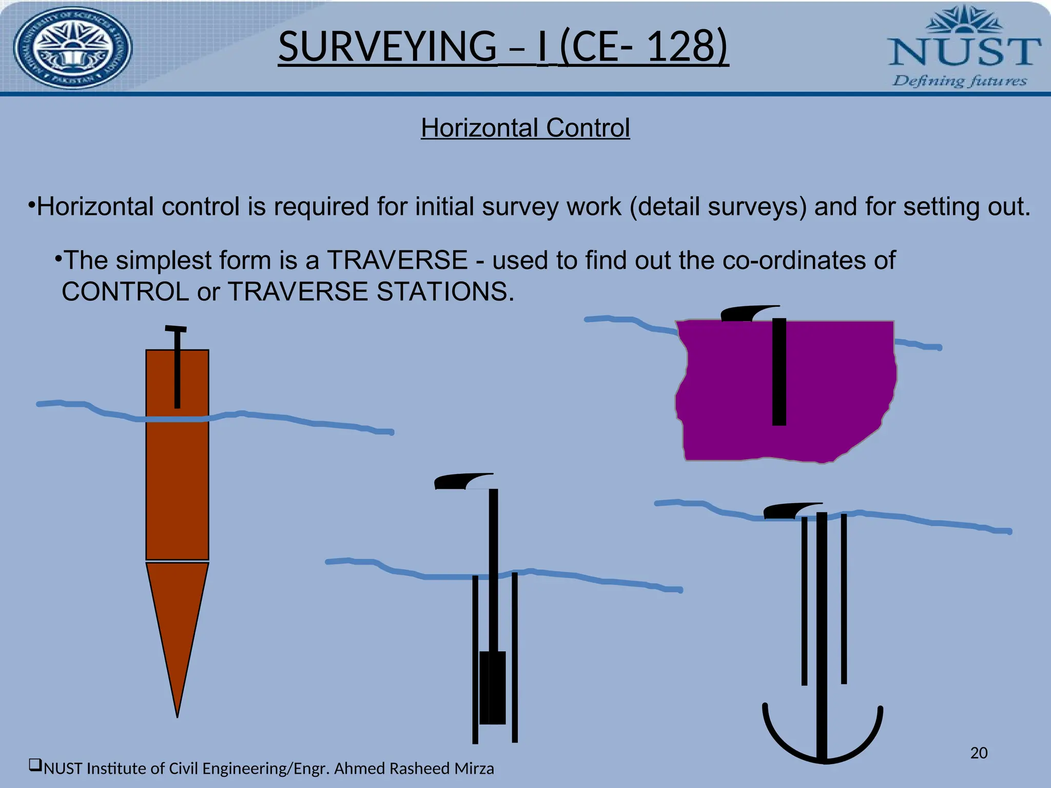
Horizontal Control
o Horizontal control is required for initial survey work (detail surveys) and for setting out.
o The simplest form is a TRAVERSE - used to find out the co-ordinates of
CONTROL or TRAVERSE STATIONS.
18
NUST Institute of Civil Engineering/Engr. Ahmed Rasheed Mirza
Horizontal Control
•Horizontal controlis required for initial survey work (detail surveys) and for setting out.
•The simplest form is a TRAVERSE - used to find out the co-ordinates of
CONTROL or TRAVERSE STATIONS.
SURVEYING – I (CE- 128)
20
NUST Institute of Civil Engineering/Engr. Ahmed Rasheed Mirza
21.
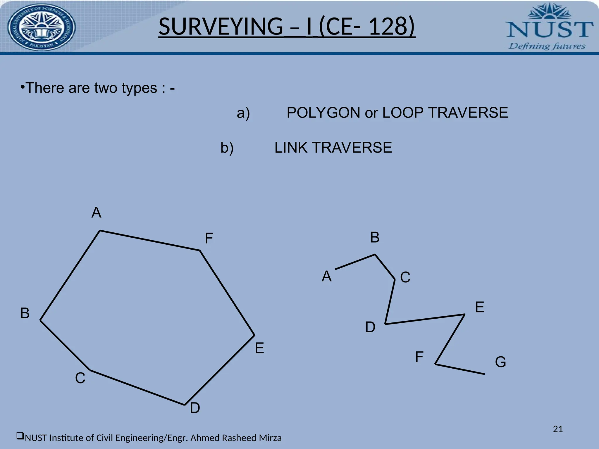
•There are twotypes : -
a) POLYGON or LOOP TRAVERSE
A
B
C
D
E
F
b) LINK TRAVERSE
B
C
D
E
F
A
G
SURVEYING – I (CE- 128)
21
NUST Institute of Civil Engineering/Engr. Ahmed Rasheed Mirza
22.
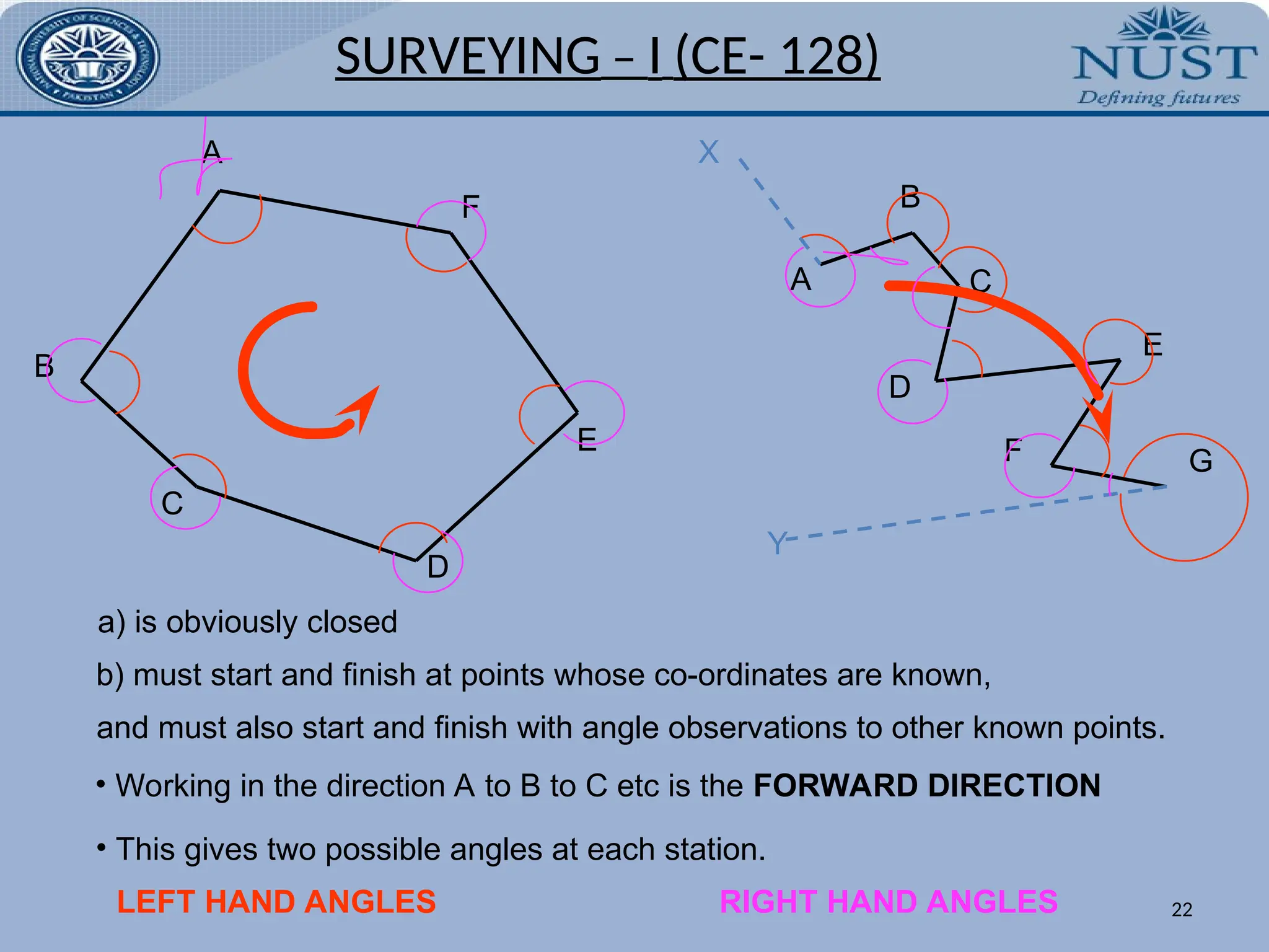
a) is obviouslyclosed
b) must start and finish at points whose co-ordinates are known,
and must also start and finish with angle observations to other known points.
• Working in the direction A to B to C etc is the FORWARD DIRECTION
• This gives two possible angles at each station.
LEFT HAND ANGLES RIGHT HAND ANGLES
A
B
C
D
E
F B
C
D
E
F
A
G
X
Y
SURVEYING – I (CE- 128)
22
23.
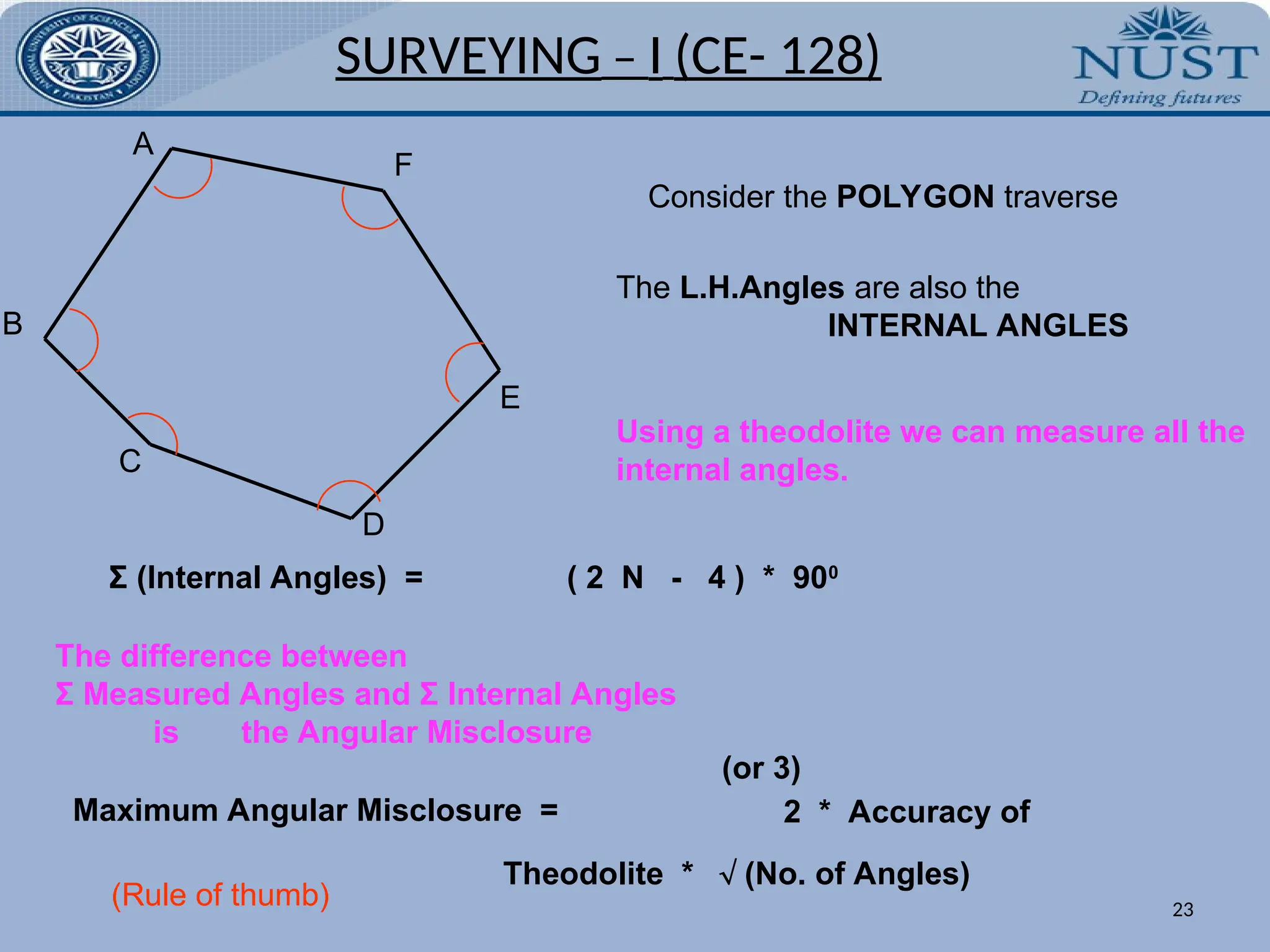
A
B
C
D
E
F
Consider the POLYGONtraverse
The L.H.Angles are also the
INTERNAL ANGLES
Σ (Internal Angles) = ( 2 N - 4 ) * 900
Using a theodolite we can measure all the
internal angles.
The difference between
Σ Measured Angles and Σ Internal Angles
is the Angular Misclosure
Maximum Angular Misclosure =
Theodolite * (No. of Angles)
2 * Accuracy of
(Rule of thumb)
(or 3)
SURVEYING – I (CE- 128)
23
24.
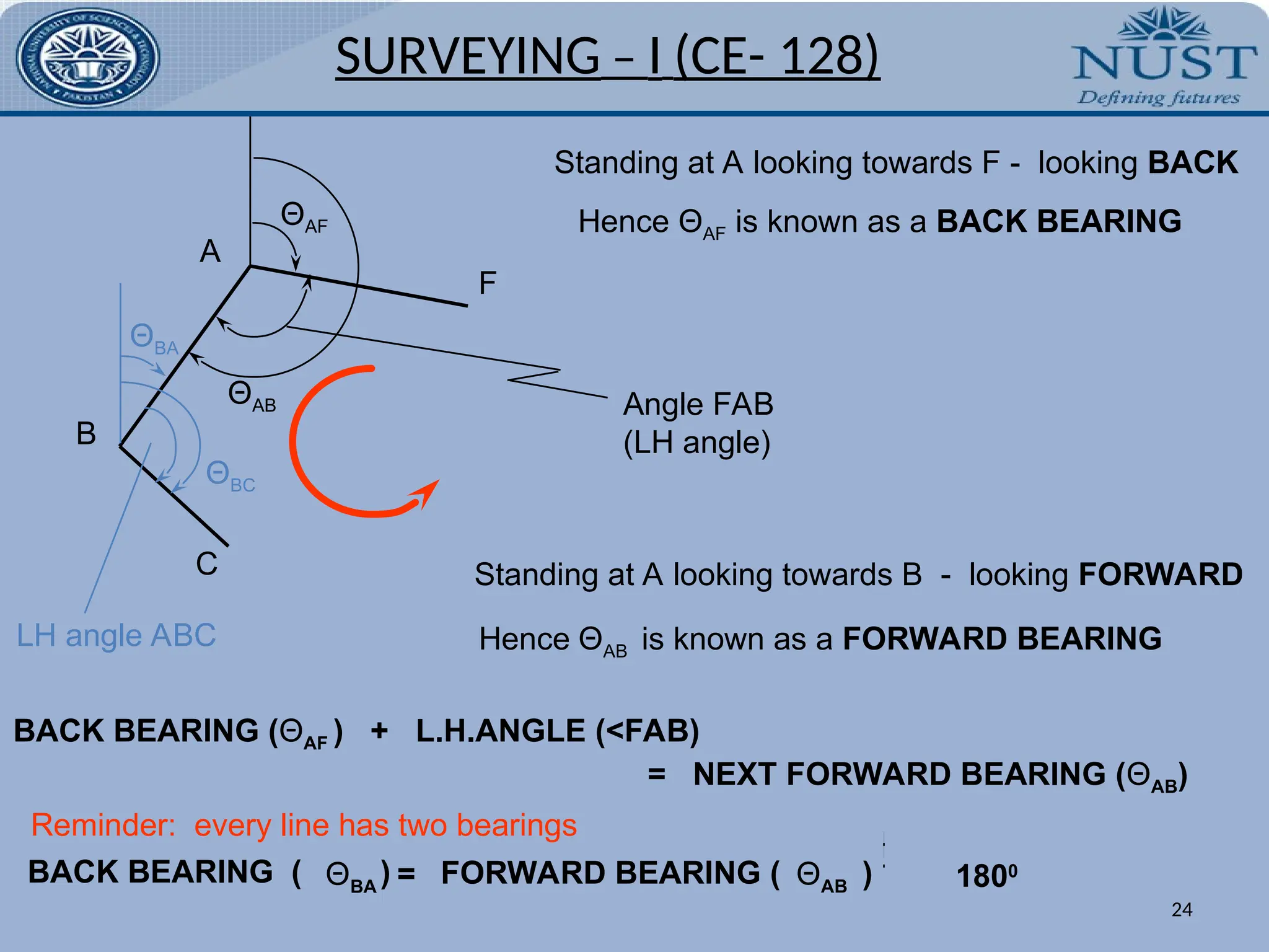
A
B
C
F
ΘAF
Standing at Alooking towards F - looking BACK
Hence ΘAF is known as a BACK BEARING
ΘAB
Standing at A looking towards B - looking FORWARD
Hence ΘAB is known as a FORWARD BEARING
Angle FAB
(LH angle)
BACK BEARING (ΘAF ) + L.H.ANGLE (<FAB)
= NEXT FORWARD BEARING (ΘAB)
Reminder: every line has two bearings
ΘBA = ΘAB
1800
FORWARD BEARING ( )
BACK BEARING ( )
ΘBA
ΘBC
LH angle ABC
SURVEYING – I (CE- 128)
24
25.
Observations, using aZeiss O15B, 6” Theodolite, were taken in the field for an
anti - clockwise polygon traverse, A, B, C, D.
Observed Clockwise
Horizontal Angle
0 ‘ “
132 15 30
31 50 30
126 12 54
Traverse Example
A
B
N
D
C Traverse Station
A
69 41 18
D
C
B
12” / 4 = 3”
Line Horizontal
Distance
638.57
1576.20
3824.10
3133.72
DA
CD
BC
AB
The bearing of line AB is to be
assumed to be 00
and the
co-ordinates of station A are
(3000.00 mE ; 4000.00 mN)
Σ (Internal Angles) = 360 00 12
Σ (Internal Angles) should be
(2N-4)*90 = 360 00 00
Allowable = 3 * 6” * N= 36”
OK - Therefore distribute error
SURVEYING – I (CE- 128)
25
26.
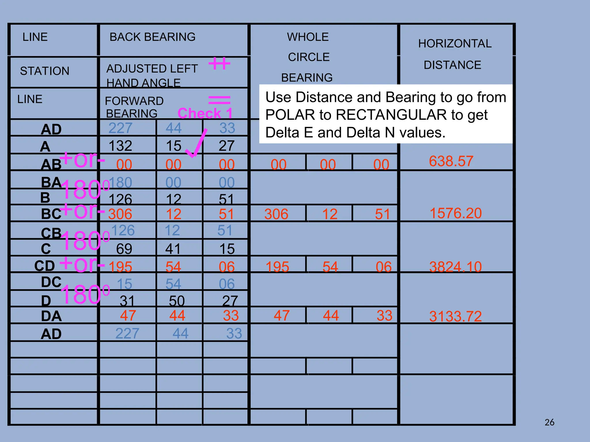
LINE BACK BEARING
STATIONADJUSTED LEFT
HAND ANGLE
LINE FORWARD
BEARING
WHOLE
CIRCLE
BEARING
HORIZONTAL
DISTANCE
D
A
B
C
D
AB
BA
BC
CB
CD
DC
DA
AD
AD
132 15 27
126 12 51
69 41 15
31 50 27
00 00 00
+or-
1800180 00 00
+
=
306 12 51
+or-
1800126 12 51
+
=
195 54 06
+or-
1800 15 54 06
47 44 33
227 44 33
227 44 33
Check 1
00 00 00
306 12 51
195 54 06
47 44 33
638.57
1576.20
3824.10
3133.72
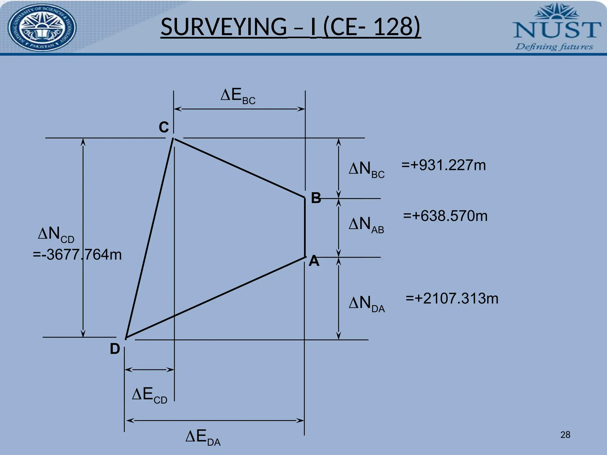
Use Distance and Bearing to go from
POLAR to RECTANGULAR to get
Delta E and Delta N values.
26
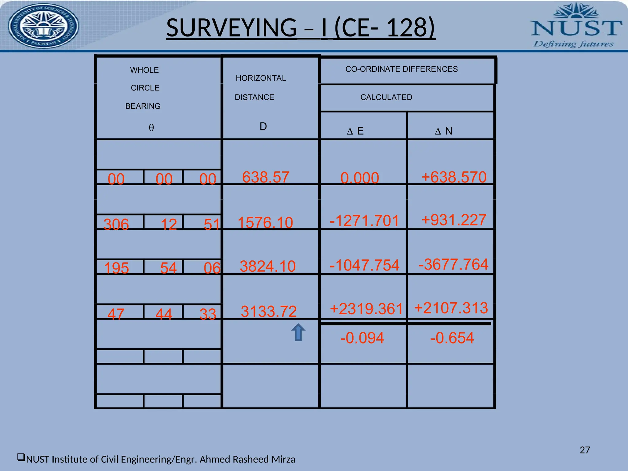
27.
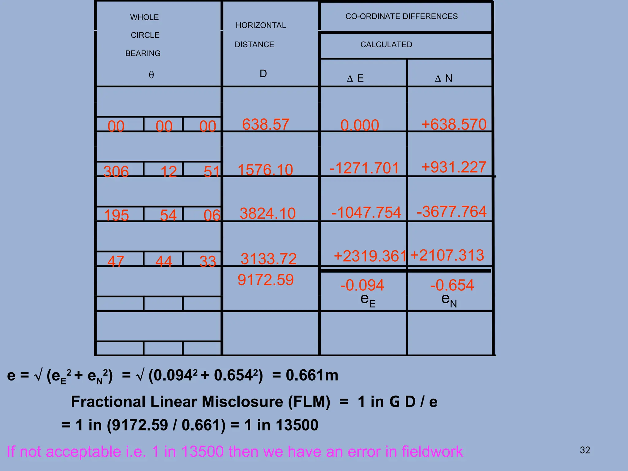
CO-ORDINATE DIFFERENCES
CALCULATED
WHOLE
CIRCLE
BEARING
HORIZONTAL
DISTANCE
D E N
00 00 00
306 12 51
195 54 06
47 44 33
638.57
1576.10
3824.10
3133.72
0.000 +638.570
-1271.701 +931.227
-1047.754 -3677.764
+2319.361 +2107.313
-0.094 -0.654
SURVEYING – I (CE- 128)
27
NUST Institute of Civil Engineering/Engr. Ahmed Rasheed Mirza
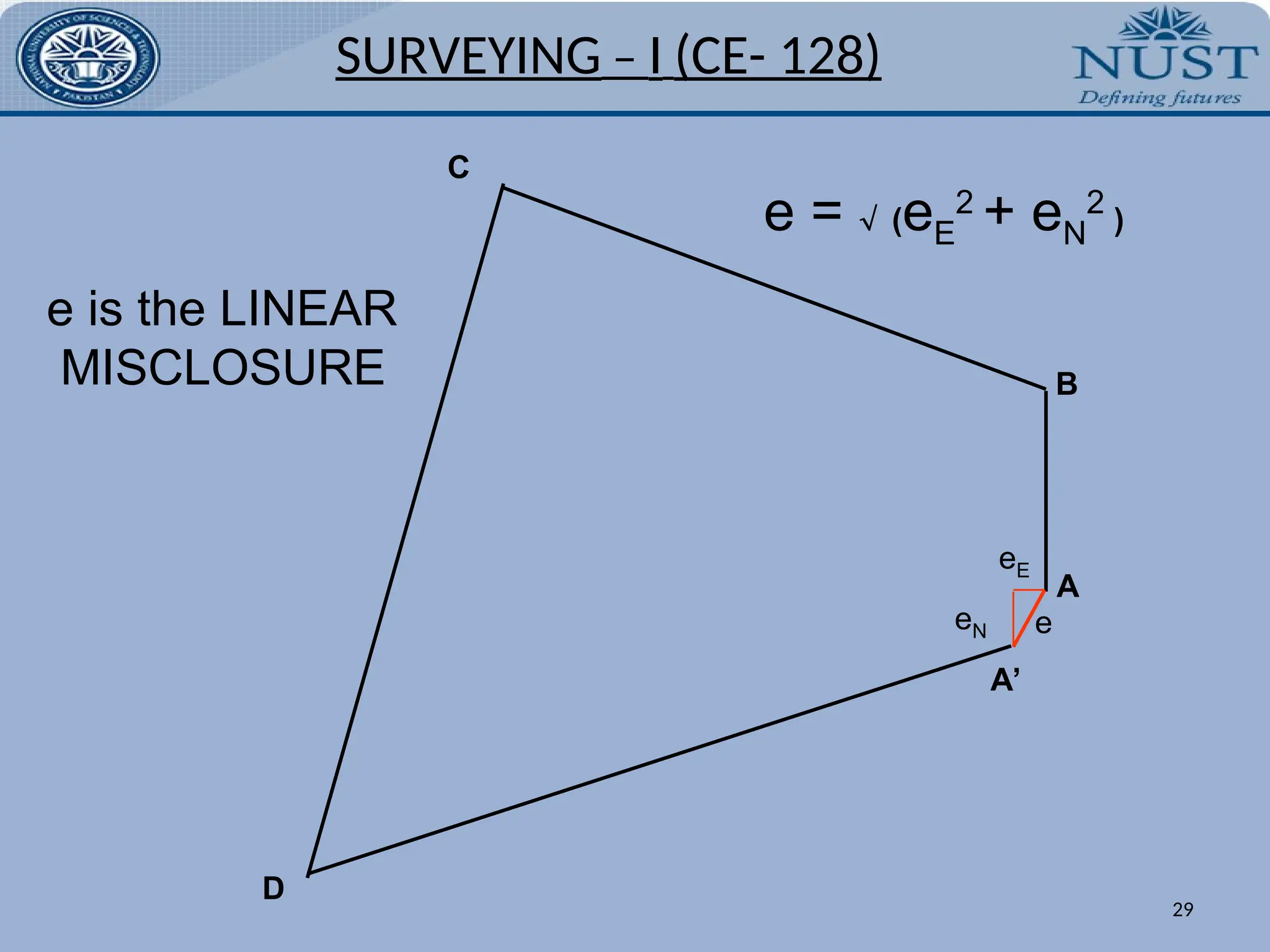
A
B
D
C
A’
eE
eN e
e isthe LINEAR
MISCLOSURE
e = (eE
2
+ eN
2
)
SURVEYING – I (CE- 128)
29
30.
CO-ORDINATE DIFFERENCES
CALCULATED
WHOLE
CIRCLE
BEARING
HORIZONTAL
DISTANCE
D E N
00 00 00
306 12 51
195 54 06
47 44 33
638.57
1576.10
3824.10
3133.72
0.000 +638.570
-1271.701 +931.227
-1047.754 -3677.764
+2319.361 +2107.313
-0.094 -0.654
eE eN
e = (eE
2
+ eN
2
) = (0.0942
+ 0.6542
) = 0.661m
Fractional Linear Misclosure (FLM) = 1 in G D / e
G G
9172.59
= 1 in (9172.59 / 0.661) = 1 in 13500
[To the nearest 500 lower value] 30
31.
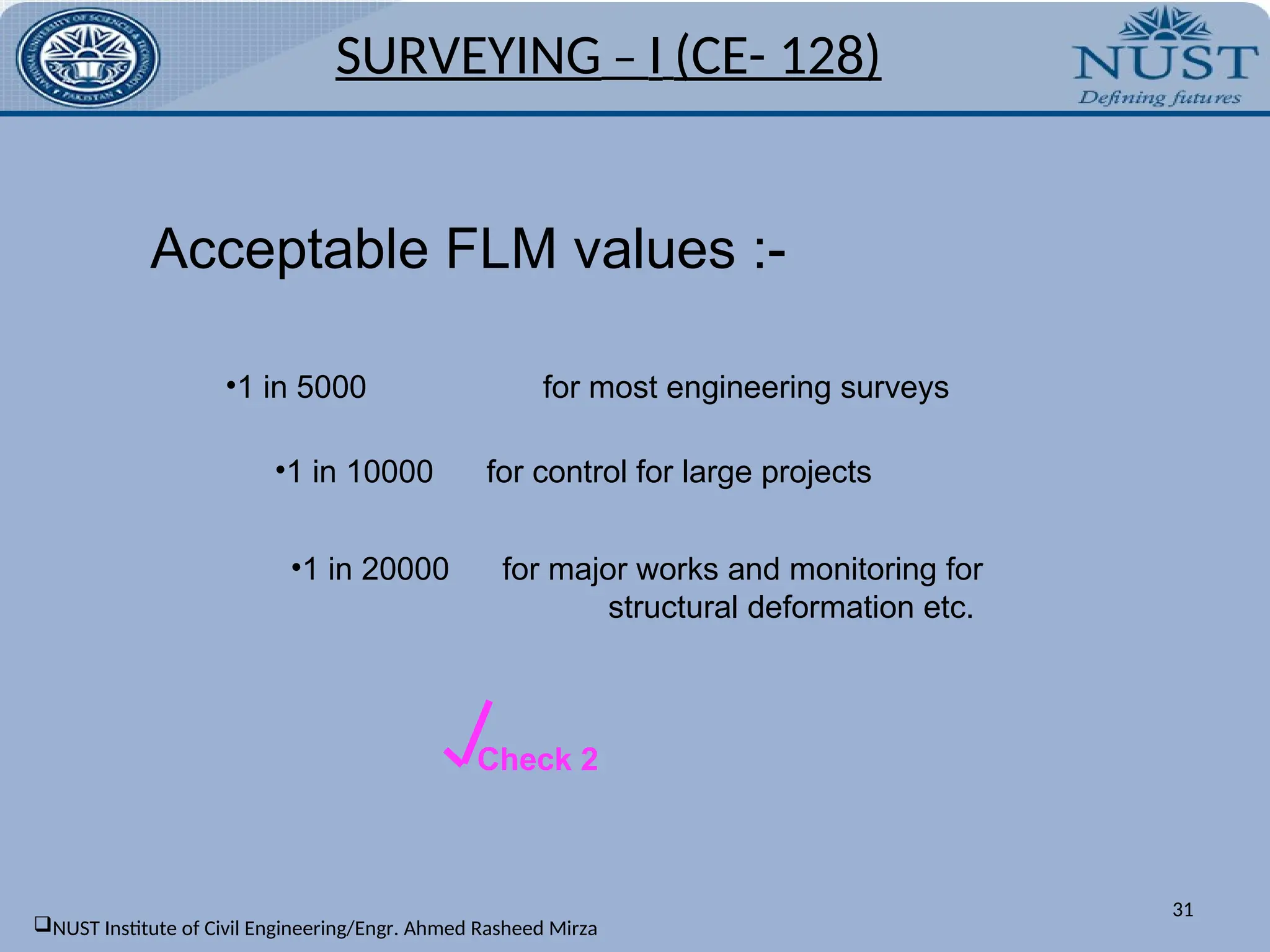
Acceptable FLM values:-
•1 in 5000 for most engineering surveys
•1 in 10000 for control for large projects
•1 in 20000 for major works and monitoring for
structural deformation etc.
Check 2
SURVEYING – I (CE- 128)
31
NUST Institute of Civil Engineering/Engr. Ahmed Rasheed Mirza
32.
CO-ORDINATE DIFFERENCES
CALCULATED
WHOLE
CIRCLE
BEARING
HORIZONTAL
DISTANCE
D E N
00 00 00
306 12 51
195 54 06
47 44 33
638.57
1576.10
3824.10
3133.72
0.000 +638.570
-1271.701 +931.227
-1047.754 -3677.764
+2319.361+2107.313
-0.094 -0.654
eE eN
9172.59
If not acceptable i.e. 1 in 13500 then we have an error in fieldwork
e = (eE
2
+ eN
2
) = (0.0942
+ 0.6542
) = 0.661m
Fractional Linear Misclosure (FLM) = 1 in G D / e
= 1 in (9172.59 / 0.661) = 1 in 13500
32
33.
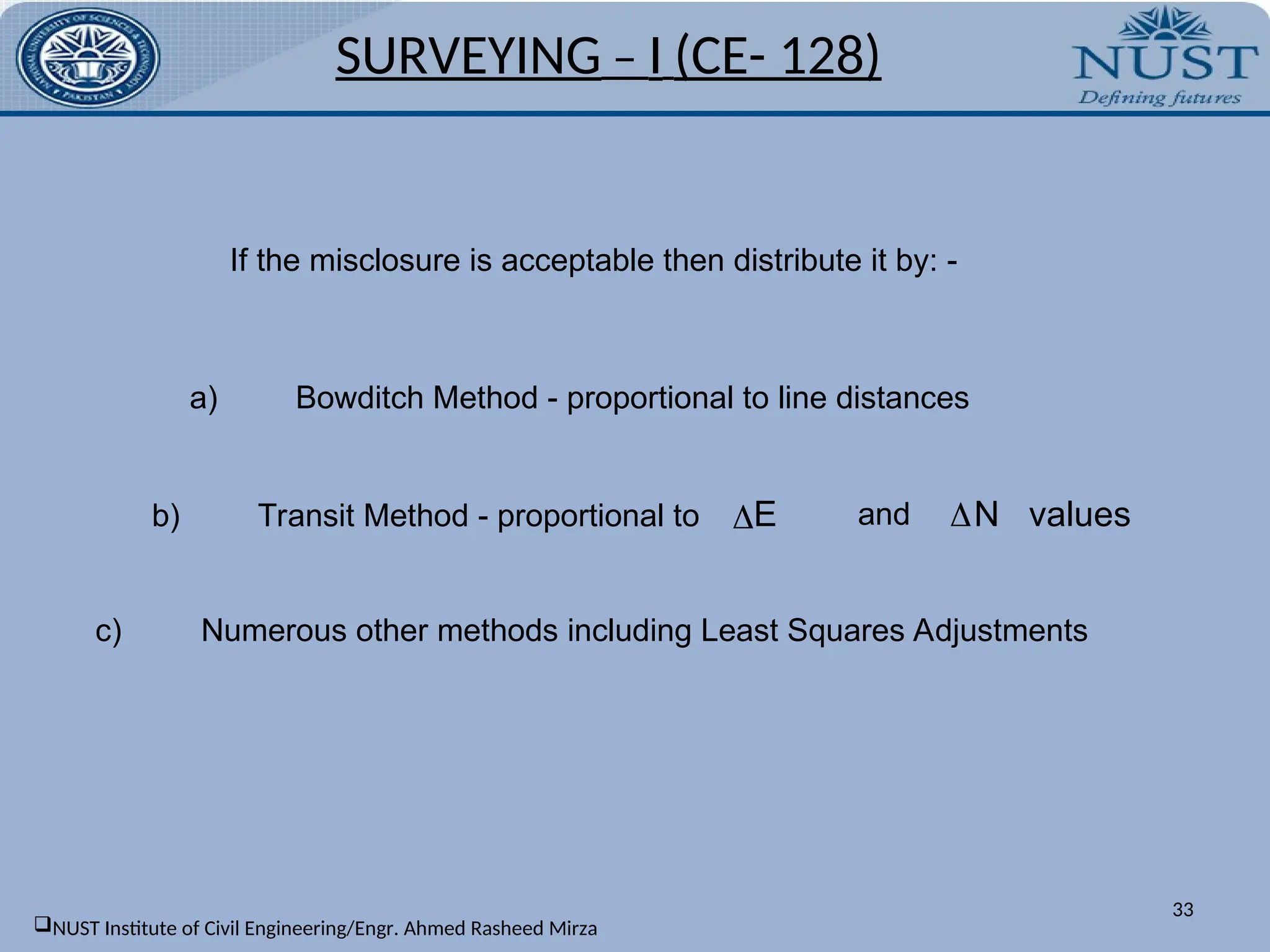
If the misclosureis acceptable then distribute it by: -
a) Bowditch Method - proportional to line distances
b) Transit Method - proportional to N values
E and
c) Numerous other methods including Least Squares Adjustments
SURVEYING – I (CE- 128)
33
NUST Institute of Civil Engineering/Engr. Ahmed Rasheed Mirza
![14
b) Given Q.B of lines:
A diagram may be drawn and bearings of the lines plotted in their respective quadrants.
The included angle is calculated from one of the under mentioned formulae:
1) If the bearings have been measured to the same side of the common meridian, the
included angle α = θ2 – θ1 i.e. the difference of the bearings. This is true for all
quadrants.[fig 4.25 a]
2) If the bearings have been measured to the opposite side of the common meridian,
the included angle α = θ1 + θ2 i.e. the sum of the bearings. [fig 4.25 b]
3) If the bearings have been measured to the same side of the different meridians, the
included angle α = 180˚ - (θ1 + θ2) i.e. the difference of 180 and the sum of the
bearings. [fig 4.25 c]
4) If the bearings have been measured to the opposite side of the different meridians,
the included angle α = 180˚ - (θ1 - θ2) i.e. the difference of 180 and the difference of
the bearings. [fig 4.25 d]
SURVEYING – I (CE- 128)
NUST Institute of Civil Engineering/Engr. Ahmed Rasheed Mirza](https://image.slidesharecdn.com/traversingcivilengineering2year-251019115540-9b8df4a0/75/TRAVERSING_civil_engineering_2_year_-ppt-14-2048.jpg)
![CO-ORDINATE DIFFERENCES
CALCULATED
WHOLE
CIRCLE
BEARING
HORIZONTAL
DISTANCE
D E N
00 00 00
306 12 51
195 54 06
47 44 33
638.57
1576.10
3824.10
3133.72
0.000 +638.570
-1271.701 +931.227
-1047.754 -3677.764
+2319.361 +2107.313
-0.094 -0.654
eE eN
e = (eE
2
+ eN
2
) = (0.0942
+ 0.6542
) = 0.661m
Fractional Linear Misclosure (FLM) = 1 in G D / e
G G
9172.59
= 1 in (9172.59 / 0.661) = 1 in 13500
[To the nearest 500 lower value] 30](https://image.slidesharecdn.com/traversingcivilengineering2year-251019115540-9b8df4a0/75/TRAVERSING_civil_engineering_2_year_-ppt-30-2048.jpg)