Downloaded 51 times
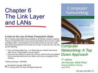


![CRC example
want:
D.2r XOR R = nG
equivalently:
D.2r = nG XOR R
equivalently:
if we divide D.2r by
G, want remainder
R to satisfy:
R = remainder[ ]
D.2r
G
6-15Link Layer and LANs
* Check out the online interactive exercises for more
examples: http://gaia.cs.umass.edu/kurose_ross/interactive/](https://image.slidesharecdn.com/chapter6v701-200606183841/85/Chapter-6-Computer-Networking-a-top-down-Approach-7th-15-320.jpg)


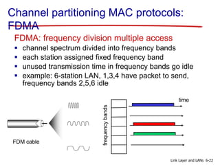


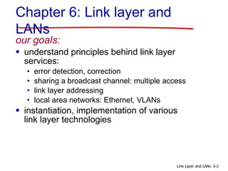
![Pure (unslotted) ALOHA
unslotted Aloha: simpler, no synchronization
when frame first arrives
• transmit immediately
collision probability increases:
• frame sent at t0 collides with other frames sent in [t0-
1,t0+1]
6-27Link Layer and LANs](https://image.slidesharecdn.com/chapter6v701-200606183841/85/Chapter-6-Computer-Networking-a-top-down-Approach-7th-27-320.jpg)
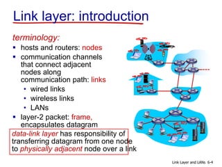
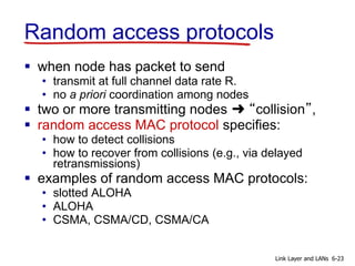
![Pure ALOHA efficiency
P(success by given node) = P(node transmits) .
P(no other node transmits in [t0-1,t0] .
P(no other node transmits in [t0-1,t0]
= p . (1-p)N-1 . (1-p)N-1
= p . (1-p)2(N-1)
… choosing optimum p and then letting n
= 1/(2e) = .18
even worse than slotted Aloha!
6-28Link Layer and LANs](https://image.slidesharecdn.com/chapter6v701-200606183841/85/Chapter-6-Computer-Networking-a-top-down-Approach-7th-28-320.jpg)
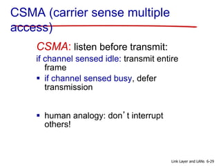


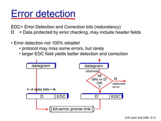
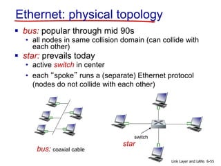
![DOCSIS: data over cable service interface spec
FDM over upstream, downstream frequency channels
TDM upstream: some slots assigned, some have
contention
• downstream MAP frame: assigns upstream slots
• request for upstream slots (and data) transmitted
random access (binary backoff) in selected slots
MAP frame for
Interval [t1, t2]
Residences with cable modems
Downstream channel i
Upstream channel j
t1 t2
Assigned minislots containing cable modem
upstream data frames
Minislots containing
minislots request frames
cable headend
CMTS
Cable access network
6-39Link Layer and LANs](https://image.slidesharecdn.com/chapter6v701-200606183841/85/Chapter-6-Computer-Networking-a-top-down-Approach-7th-39-320.jpg)


This document provides an overview and outline of topics to be covered in a chapter about the link layer and local area networks (LANs). It discusses the goals of understanding link layer services like error detection and correction as well as sharing bandwidth on a broadcast channel. It also outlines the key sections to be covered, including multiple access protocols, LAN addressing, Ethernet, switches, and virtual LANs. Sample slides are provided on topics like link layer services, error detection techniques, and multiple access protocols. The document is intended for educational use and asks that the source be cited if used for teaching.