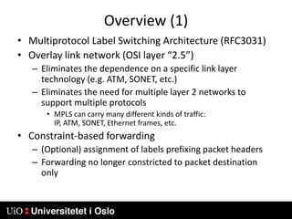
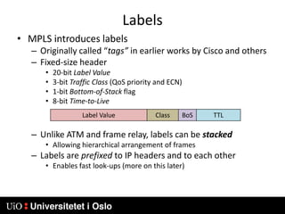
1) MPLS introduces labels that are prefixed to packet headers and allows forwarding based on these labels instead of long IP addresses, enabling traffic engineering.
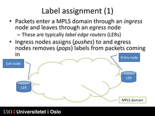
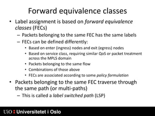
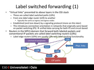
2) Labels are assigned based on forward equivalence classes which group packets that should follow the same path. This path is called a label switched path (LSP).
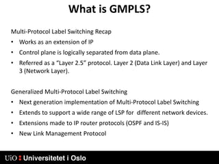
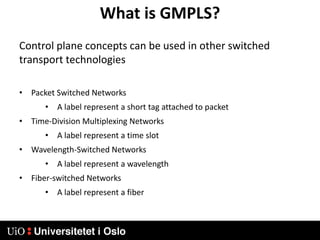
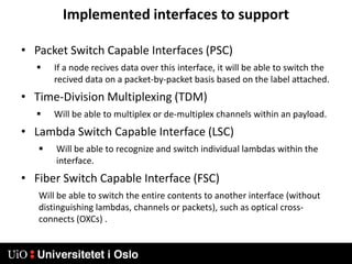
3) Generalized MPLS (GMPLS) extends MPLS to support a wider range of network types and interfaces beyond IP routers, including support for optical and time-division multiplexing networks. It enhances signaling protocols and introduces hierarchical LSP setup.