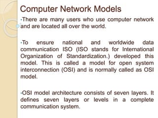
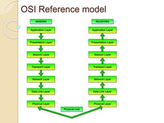
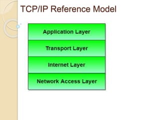
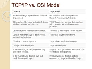
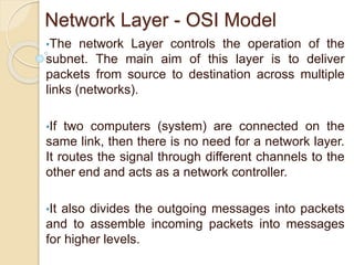
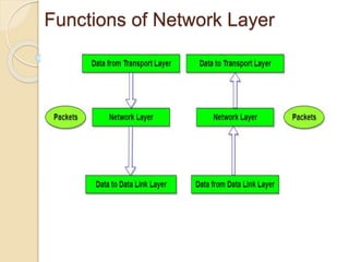
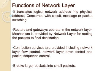
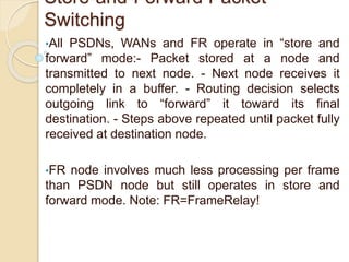
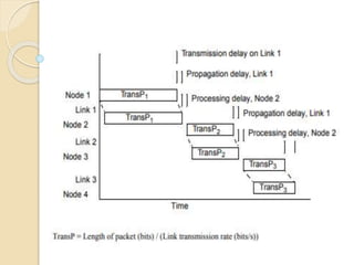
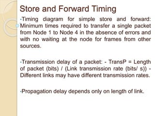
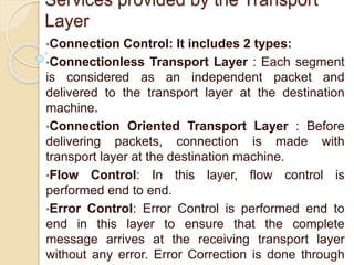
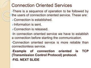
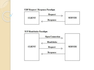
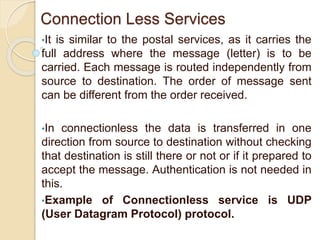
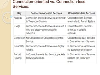
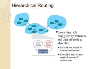
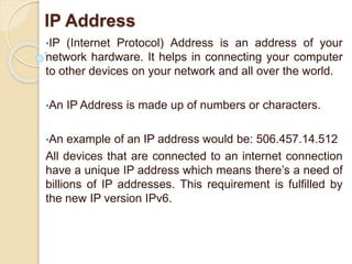
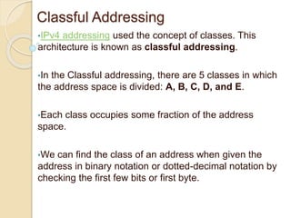
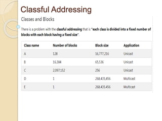
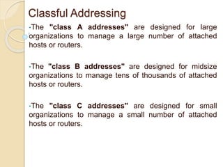
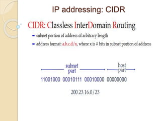
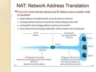
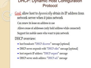
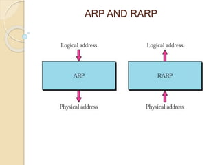
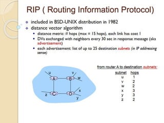
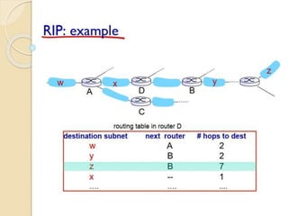
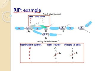
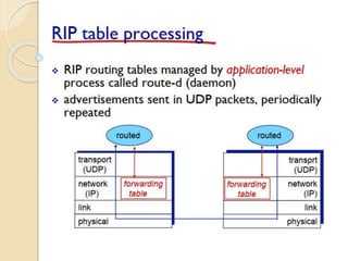
Computer Network Models
•There are many users who use computer network
and are located all over the world.
•To ensure national and worldwide data
communication ISO (ISO stands for International
Organization of Standardization.) developed this
model. This is called a model for open system
interconnection (OSI) and is normally called as OSI
model.
•OSI model architecture consists of seven layers. It
defines seven layers or levels in a complete
communication system.
OSI Reference model
TCP/IP Reference Model
•There are many users who use computer network
and are located all over the world.
•To ensure national and worldwide data
communication ISO (ISO stands for International
Organization of Standardization.) developed this
model. This is called a model for open system
interconnection (OSI) and is normally called as OSI
model.
•OSI model architecture consists of seven layers. It
defines seven layers or levels in a complete
communication system.
TCP/IP Reference Model
TCP/IP vs. OSI Model
Network Layer - OSI Model
•The network Layer controls the operation of the
subnet. The main aim of this layer is to deliver
packets from source to destination across multiple
links (networks).
•If two computers (system) are connected on the
same link, then there is no need for a network layer.
It routes the signal through different channels to the
other end and acts as a network controller.
•It also divides the outgoing messages into packets
and to assemble incoming packets into messages
for higher levels.
Functions of Network Layer
•It translates logical network address into physical
address. Concerned with circuit, message or packet
switching.
•Routers and gateways operate in the network layer.
Mechanism is provided by Network Layer for routing
the packets to final destination.
•Connection services are provided including network
layer flow control, network layer error control and
packet sequence control.
•Breaks larger packets into small packets.
Store-and-Forward Packet
Switching
•All PSDNs, WANs and FR operate in “store and
forward” mode:- Packet stored at a node and
transmitted to next node. - Next node receives it
completely in a buffer. - Routing decision selects
outgoing link to “forward” it toward its final
destination. - Steps above repeated until packet fully
received at destination node.
•FR node involves much less processing per frame
than PSDN node but still operates in store and
forward mode. Note: FR=FrameRelay!
Store and Forward Timing
•Timing diagram for simple store and forward:
Minimum times required to transfer a single packet
from Node 1 to Node 4 in the absence of errors and
with no waiting at the node for frames from other
sources.
•Transmission delay of a packet: - TransP = Length
of packet (bits) / (Link transmission rate (bits/ s)) -
Different links may have different transmission rates.
•Propagation delay depends only on length of link.
Effects of Packet Size
•Above figure shows file transfer from Station X to
Station Y through intermediate store-and-forward
nodes a and b.
•Effect of length of packets on file transfer delay:-
Segmentation into smaller packets shortens delay
up to a point by reducing the store and forward
delay at each node.
•But cause extra overhead in packet headers and in
processing requirements at nodes which may
increase processing delays .
Services provided by the Transport
Layer
•Service Point Addressing: Transport Layer header
includes service point address which is port
address. This layer gets the message to the correct
process on the computer unlike Network Layer,
which gets each packet to the correct computer.
•Segmentation and Reassembling: A message is
divided into segments; each segment contains
sequence number, which enables this layer in
reassembling the message. Message is
reassembled correctly upon arrival at the destination
and replaces packets which were lost in
transmission.
Services provided by the Transport
Layer
•Connection Control: It includes 2 types:
•Connectionless Transport Layer : Each segment
is considered as an independent packet and
delivered to the transport layer at the destination
machine.
•Connection Oriented Transport Layer : Before
delivering packets, connection is made with
transport layer at the destination machine.
•Flow Control: In this layer, flow control is
performed end to end.
•Error Control: Error Control is performed end to
end in this layer to ensure that the complete
message arrives at the receiving transport layer
without any error. Error Correction is done through
Connection Oriented Services
•There is a sequence of operation to be followed by
the users of connection oriented service. These are:
Connection is established.
Information is sent.
Connection is released.
•In connection oriented service we have to establish
a connection before starting the communication.
•Connection oriented service is more reliable than
connectionless service.
•Example of connection oriented is TCP
(Transmission Control Protocol) protocol.
•FIG. NEXT SLIDE
Connection Less Services
•It is similar to the postal services, as it carries the
full address where the message (letter) is to be
carried. Each message is routed independently from
source to destination. The order of message sent
can be different from the order received.
•In connectionless the data is transferred in one
direction from source to destination without checking
that destination is still there or not or if it prepared to
accept the message. Authentication is not needed in
this.
•Example of Connectionless service is UDP
(User Datagram Protocol) protocol.
Connection-oriented vs. Connection-less
Services.
Flooding
•When node receives broadcast packet, sends copy to
all neighbors.
•Problems: cycles & broadcast storm
•Controlled flooding: Node only broadcasts pkt if it
hasn’t broadcast same packet before.
•Node keeps track of packet ids already broadcasted.
•or reverse path forwarding (RPF): only forward packet
if it arrived on shortest path between node and source.
Shortest Path Routing - Dijkstra's
algorithm
Example
LINK STATE ROUTING ALGORITHM
Hierarchical Routing
IP Address
•IP (Internet Protocol) Address is an address of your
network hardware. It helps in connecting your computer
to other devices on your network and all over the world.
•An IP Address is made up of numbers or characters.
•An example of an IP address would be: 506.457.14.512
All devices that are connected to an internet connection
have a unique IP address which means there’s a need of
billions of IP addresses. This requirement is fulfilled by
the new IP version IPv6.
Classful Addressing
•IPv4 addressing used the concept of classes. This
architecture is known as classful addressing.
•In the Classful addressing, there are 5 classes in which
the address space is divided: A, B, C, D, and E.
•Each class occupies some fraction of the address
space.
•We can find the class of an address when given the
address in binary notation or dotted-decimal notation by
checking the first few bits or first byte.
Classful Addressing
Classful Addressing
•The "class A addresses" are designed for large
organizations to manage a large number of attached
hosts or routers.
•The "class B addresses" are designed for midsize
organizations to manage tens of thousands of attached
hosts or routers.
•The "class C addresses" are designed for small
organizations to manage a small number of attached
hosts or routers.
Classless Addressing
•Classful addressing leads to address depletion. That's
the big issue for this schema and that's why it's not used
nowadays.
•To overcome the problem of address depletion and to
give more organizations access to the Internet, the
classless addressing was designed and implemented.
•In this scheme of classless addressing, there are no
classes, but the addresses are still granted in blocks.
Classless Addressing
•In classless addressing, when an entity(organization or a
single household (small organization) or whatever which uses
the internet) needs to be connected to the Internet, it is
granted a block (range) of addresses.
•The size of the block (the number of addresses) varies based
on the nature, size, and need of the entity.
•For example, a household (small organization) may be given
only two addresses; a large organization may be given
thousands of addresses.
•On the other hand. An ISP, as the Internet service provider,
may be given hundreds of thousands based on the number of
customers it may serve.
•
Subnets
Subnets
IP addressing: CIDR
NAT: Network Address Translation
DHCP: Dynamic Host Configuration
Protocol
ARP AND RARP
ARP AND RARP EXAMPLE
SOLUTION
INTERNET PROTOCOL VERSION
4(IPV4)
•IPv4 is the first network protocol to
interconnect different networks
regardless of the medium used.
•Globally unique addressing scheme
•Any two nodes can communicate
directly
ICMP: Internet Control Message
Protocol
ICMP Header Format
IP fragmentation
IP fragmentation Example
RIP ( Routing Information Protocol)
Techniques to Improve QoS
•Scheduling
•Packets from different flows arrive at a switch or router
for processing. A good scheduling technique treats the
different flows in a fair and appropriate manner.
•Several scheduling techniques are designed to improve
the quality of service. We discuss three of them here:
FIFO queuing, priority queuing, and weighted fair
queuing.
Congestion Control techniques in Computer Networks
Open Loop Congestion Control
•Retransmission Policy :
It is the policy in which retransmission of the packets are
taken care.
•Window Policy :
The type of window at the sender side may also affect
the congestion.
•Discarding Policy :
A good discarding policy adopted by the routers is that
the routers may prevent congestion and at the same time
partially discards the corrupted or less sensitive package
and also able to maintain the quality of a message.
Open Loop Congestion Control
•Acknowledgment Policy :
Since acknowledgement are also the part of the load in
network, the acknowledgment policy imposed by the
receiver may also affect congestion. Several approaches
can be used to prevent congestion related to
acknowledgment.
•Admission Policy :
In admission policy a mechanism should be used to
prevent congestion. Switches in a flow should first check
the resource requirement of a network flow before
transmitting it further.
Closed Loop Congestion Control
Network layer
Network layer

Network layer

  • 1.
    Computer Network Models •Thereare many users who use computer network and are located all over the world. •To ensure national and worldwide data communication ISO (ISO stands for International Organization of Standardization.) developed this model. This is called a model for open system interconnection (OSI) and is normally called as OSI model. •OSI model architecture consists of seven layers. It defines seven layers or levels in a complete communication system.
  • 2.
  • 3.
    TCP/IP Reference Model •Thereare many users who use computer network and are located all over the world. •To ensure national and worldwide data communication ISO (ISO stands for International Organization of Standardization.) developed this model. This is called a model for open system interconnection (OSI) and is normally called as OSI model. •OSI model architecture consists of seven layers. It defines seven layers or levels in a complete communication system.
  • 4.
  • 5.
  • 6.
    Network Layer -OSI Model •The network Layer controls the operation of the subnet. The main aim of this layer is to deliver packets from source to destination across multiple links (networks). •If two computers (system) are connected on the same link, then there is no need for a network layer. It routes the signal through different channels to the other end and acts as a network controller. •It also divides the outgoing messages into packets and to assemble incoming packets into messages for higher levels.
  • 7.
  • 8.
    Functions of NetworkLayer •It translates logical network address into physical address. Concerned with circuit, message or packet switching. •Routers and gateways operate in the network layer. Mechanism is provided by Network Layer for routing the packets to final destination. •Connection services are provided including network layer flow control, network layer error control and packet sequence control. •Breaks larger packets into small packets.
  • 9.
    Store-and-Forward Packet Switching •All PSDNs,WANs and FR operate in “store and forward” mode:- Packet stored at a node and transmitted to next node. - Next node receives it completely in a buffer. - Routing decision selects outgoing link to “forward” it toward its final destination. - Steps above repeated until packet fully received at destination node. •FR node involves much less processing per frame than PSDN node but still operates in store and forward mode. Note: FR=FrameRelay!
  • 11.
    Store and ForwardTiming •Timing diagram for simple store and forward: Minimum times required to transfer a single packet from Node 1 to Node 4 in the absence of errors and with no waiting at the node for frames from other sources. •Transmission delay of a packet: - TransP = Length of packet (bits) / (Link transmission rate (bits/ s)) - Different links may have different transmission rates. •Propagation delay depends only on length of link.
  • 13.
    Effects of PacketSize •Above figure shows file transfer from Station X to Station Y through intermediate store-and-forward nodes a and b. •Effect of length of packets on file transfer delay:- Segmentation into smaller packets shortens delay up to a point by reducing the store and forward delay at each node. •But cause extra overhead in packet headers and in processing requirements at nodes which may increase processing delays .
  • 14.
    Services provided bythe Transport Layer •Service Point Addressing: Transport Layer header includes service point address which is port address. This layer gets the message to the correct process on the computer unlike Network Layer, which gets each packet to the correct computer. •Segmentation and Reassembling: A message is divided into segments; each segment contains sequence number, which enables this layer in reassembling the message. Message is reassembled correctly upon arrival at the destination and replaces packets which were lost in transmission.
  • 16.
    Services provided bythe Transport Layer •Connection Control: It includes 2 types: •Connectionless Transport Layer : Each segment is considered as an independent packet and delivered to the transport layer at the destination machine. •Connection Oriented Transport Layer : Before delivering packets, connection is made with transport layer at the destination machine. •Flow Control: In this layer, flow control is performed end to end. •Error Control: Error Control is performed end to end in this layer to ensure that the complete message arrives at the receiving transport layer without any error. Error Correction is done through
  • 17.
    Connection Oriented Services •Thereis a sequence of operation to be followed by the users of connection oriented service. These are: Connection is established. Information is sent. Connection is released. •In connection oriented service we have to establish a connection before starting the communication. •Connection oriented service is more reliable than connectionless service. •Example of connection oriented is TCP (Transmission Control Protocol) protocol. •FIG. NEXT SLIDE
  • 19.
    Connection Less Services •Itis similar to the postal services, as it carries the full address where the message (letter) is to be carried. Each message is routed independently from source to destination. The order of message sent can be different from the order received. •In connectionless the data is transferred in one direction from source to destination without checking that destination is still there or not or if it prepared to accept the message. Authentication is not needed in this. •Example of Connectionless service is UDP (User Datagram Protocol) protocol.
  • 20.
  • 21.
    Flooding •When node receivesbroadcast packet, sends copy to all neighbors. •Problems: cycles & broadcast storm •Controlled flooding: Node only broadcasts pkt if it hasn’t broadcast same packet before. •Node keeps track of packet ids already broadcasted. •or reverse path forwarding (RPF): only forward packet if it arrived on shortest path between node and source.
  • 22.
    Shortest Path Routing- Dijkstra's algorithm
  • 24.
  • 34.
  • 35.
  • 36.
  • 37.
    IP Address •IP (InternetProtocol) Address is an address of your network hardware. It helps in connecting your computer to other devices on your network and all over the world. •An IP Address is made up of numbers or characters. •An example of an IP address would be: 506.457.14.512 All devices that are connected to an internet connection have a unique IP address which means there’s a need of billions of IP addresses. This requirement is fulfilled by the new IP version IPv6.
  • 38.
    Classful Addressing •IPv4 addressingused the concept of classes. This architecture is known as classful addressing. •In the Classful addressing, there are 5 classes in which the address space is divided: A, B, C, D, and E. •Each class occupies some fraction of the address space. •We can find the class of an address when given the address in binary notation or dotted-decimal notation by checking the first few bits or first byte.
  • 39.
  • 40.
    Classful Addressing •The "classA addresses" are designed for large organizations to manage a large number of attached hosts or routers. •The "class B addresses" are designed for midsize organizations to manage tens of thousands of attached hosts or routers. •The "class C addresses" are designed for small organizations to manage a small number of attached hosts or routers.
  • 41.
    Classless Addressing •Classful addressingleads to address depletion. That's the big issue for this schema and that's why it's not used nowadays. •To overcome the problem of address depletion and to give more organizations access to the Internet, the classless addressing was designed and implemented. •In this scheme of classless addressing, there are no classes, but the addresses are still granted in blocks.
  • 42.
    Classless Addressing •In classlessaddressing, when an entity(organization or a single household (small organization) or whatever which uses the internet) needs to be connected to the Internet, it is granted a block (range) of addresses. •The size of the block (the number of addresses) varies based on the nature, size, and need of the entity. •For example, a household (small organization) may be given only two addresses; a large organization may be given thousands of addresses. •On the other hand. An ISP, as the Internet service provider, may be given hundreds of thousands based on the number of customers it may serve. •
  • 43.
  • 44.
  • 45.
  • 46.
  • 47.
    DHCP: Dynamic HostConfiguration Protocol
  • 48.
  • 49.
    ARP AND RARPEXAMPLE
  • 50.
  • 51.
    INTERNET PROTOCOL VERSION 4(IPV4) •IPv4is the first network protocol to interconnect different networks regardless of the medium used. •Globally unique addressing scheme •Any two nodes can communicate directly
  • 52.
    ICMP: Internet ControlMessage Protocol
  • 53.
  • 54.
  • 55.
  • 56.
    RIP ( RoutingInformation Protocol)
  • 67.
    Techniques to ImproveQoS •Scheduling •Packets from different flows arrive at a switch or router for processing. A good scheduling technique treats the different flows in a fair and appropriate manner. •Several scheduling techniques are designed to improve the quality of service. We discuss three of them here: FIFO queuing, priority queuing, and weighted fair queuing.
  • 71.
    Congestion Control techniquesin Computer Networks
  • 72.
    Open Loop CongestionControl •Retransmission Policy : It is the policy in which retransmission of the packets are taken care. •Window Policy : The type of window at the sender side may also affect the congestion. •Discarding Policy : A good discarding policy adopted by the routers is that the routers may prevent congestion and at the same time partially discards the corrupted or less sensitive package and also able to maintain the quality of a message.
  • 73.
    Open Loop CongestionControl •Acknowledgment Policy : Since acknowledgement are also the part of the load in network, the acknowledgment policy imposed by the receiver may also affect congestion. Several approaches can be used to prevent congestion related to acknowledgment. •Admission Policy : In admission policy a mechanism should be used to prevent congestion. Switches in a flow should first check the resource requirement of a network flow before transmitting it further.
  • 74.
  • 75.
  • 76.