Design by Analysis - A general guideline for pressure vesselAnalyzeForSafety
This presentation file is provided by Mr. Ghanbari and published under permission.
The presentation gives an introduction and general guideline for pressure vessel design by analysis.
The “design by analysis” procedures are intended to guard against eight possible pressure vessel failure modes by performing a detailed stress analysis of the vessel with the sufficient design factors. The failure modes are:
1.excessive elastic deformation, including elastic instability,
2.excessive plastic deformation,
3.brittle fracture,
4.stress rupture/creep deformation (inelastic),
5.plastic instability - incremental collapse,
6.high strain - low cycle fatigue,
7.stress corrosion, and
8.corrosion fatigue
Most of the “design by analysis” procedures that are given in ASME BPVC relate to designs based on “elastic analysis.”
The design-by-analysis requirements are organized based on protection against the failure modes listed below. The component shall be evaluated for each applicable failure mode. If multiple assessment procedures are provided for a failure mode, only one of these procedures must be satisfied to qualify the design of a component.
a)All pressure vessels within the scope of this Division, irrespective of size or pressure, shall be provided with protection against overpressure in accordance with the requirements of this Part.
b)Protection Against Plastic Collapse – these requirements apply to all components where the thickness and configuration of the component is established using design-by-analysis rules.
c)Protection Against Local Failure – these requirements apply to all components where the thickness and configuration of the component is established using design-by-analysis rules. It is not necessary to evaluate the local strain limit criterion if the component design is in accordance with Part 4 (i.e. component wall thickness and weld detail per paragraph 4.2).
d)Protection Against Collapse From Buckling – these requirements apply to all components where the thickness and configuration of the component is established using design-by-analysis rules and the applied loads result in a compressive stress field.
e)Protection Against Failure From Cyclic Loading – these requirements apply to all components where the thickness and configuration of the component is established using design-by-analysis rules and the applied loads are cyclic. In addition, these requirements can also be used to qualify a component for cyclic loading where the thickness and size of the component are established using the design-by-rule requirements of Part 4.
The Certified Welding Inspector (CWI) plays an important role during any welded construction activities ensuring the required specifications and standards are followed. Due to the numerous materials and processes associated with metal joining (welding) THIS PRESENTATION SHALL SHOW ONLY THE BASIC WELDING PROCESSES AND EXAMINATION METHODS (NDE). National and International Codes and Specifications along with measuring devices are the Inspector’s tools. Hopefully the following presentation shall give an insight into basic welding inspection.
Impact Testing of metals is performed to determine the impact resistance or toughness of materials by calculating the amount of energy absorbed during fracture. The impact test is performed at various temperatures to uncover any effects on impact energy. These services provide test results that can be very useful in assessing the suitability of a material for a specific application and in predicting its expected service life.
Microstructure and Hardness observation of HEAT AFFECTED ZONE of low carbon s...Mukesh Karnik
TO study HEAT AFFECTED ZONE of low carbon steel(Mild steel),
Micro-structure observation of heat affected zone of mild steel,
Hardness test done of mild steel at their different zones.
at the result we find out that the HAZ zone grain was more coarser than base metal and HAZ zone.
due to sudden cooling at fusion zone micro structure columnar form which increase the hardness at that zone much more.
How to calculate gate area require for hpdc die casting partShuvamKumar9
For Getting gate area we need to know:
1.Casting Volume after gate including Overflow
2.Average wall thickness
3.Cavity fill time
4.Allowed gate velocity
5. Flow Rate
Must watch this video you understand everything about getting the gate area in detail with Calculations.
Please also watch my old video in Die Casting Die Design Playlist.
https://youtu.be/WhnFeAvz6eU
When you like my videos please do not forget to subscribe
for Subscribe you simply need to click the link below;
https://www.youtube.com/channel/UCLsS...
Inventory System Defined
Purpose and types of inventory
Independent vs. Dependent Demand
Single-Period Inventory Model
Multi-Period Inventory Models: Basic Fixed-Order Quantity Models
Multi-Period Inventory Models: Basic Fixed-Time Period Model
Miscellaneous Systems and Issues
A-B-C Approach
Inventory costs
Discuss the behavioral aspects of projects in terms of project personnel and the project manager.
Give a general description of PERT/CPM techniques.
Analyze networks with deterministic times.
Analyze networks with probabilistic times.
linear transformation and rank nullity theorem Manthan Chavda
In these notes, I will present everything we know so far about linear transformations.
This material comes from sections in the book, and supplemental that
I talk about in class.
The term regression was 1st used by the british biomethician sir
Francis Galton. While studying the relation between average
height of their children ,Galton found that the off springs of
abnormally tall or short parents tend to regress or step back to the
average population height . in the course of time the meaning of
the word “ Regreassion “ become wider and now it stands to
measure the average relationship between different variables. If
there are only 2 variable under study then one is taken as
independent and another is taken as dependent variable and
regression analysis explain how on the average the values of the
dependent variable change with a change in the values of the
independent variable.
Welcome to WIPAC Monthly the magazine brought to you by the LinkedIn Group Water Industry Process Automation & Control.
In this month's edition, along with this month's industry news to celebrate the 13 years since the group was created we have articles including
A case study of the used of Advanced Process Control at the Wastewater Treatment works at Lleida in Spain
A look back on an article on smart wastewater networks in order to see how the industry has measured up in the interim around the adoption of Digital Transformation in the Water Industry.
Sachpazis:Terzaghi Bearing Capacity Estimation in simple terms with Calculati...Dr.Costas Sachpazis
Terzaghi's soil bearing capacity theory, developed by Karl Terzaghi, is a fundamental principle in geotechnical engineering used to determine the bearing capacity of shallow foundations. This theory provides a method to calculate the ultimate bearing capacity of soil, which is the maximum load per unit area that the soil can support without undergoing shear failure. The Calculation HTML Code included.
Cosmetic shop management system project report.pdfKamal Acharya
Buying new cosmetic products is difficult. It can even be scary for those who have sensitive skin and are prone to skin trouble. The information needed to alleviate this problem is on the back of each product, but it's thought to interpret those ingredient lists unless you have a background in chemistry.
Instead of buying and hoping for the best, we can use data science to help us predict which products may be good fits for us. It includes various function programs to do the above mentioned tasks.
Data file handling has been effectively used in the program.
The automated cosmetic shop management system should deal with the automation of general workflow and administration process of the shop. The main processes of the system focus on customer's request where the system is able to search the most appropriate products and deliver it to the customers. It should help the employees to quickly identify the list of cosmetic product that have reached the minimum quantity and also keep a track of expired date for each cosmetic product. It should help the employees to find the rack number in which the product is placed.It is also Faster and more efficient way.
Student information management system project report ii.pdfKamal Acharya
Our project explains about the student management. This project mainly explains the various actions related to student details. This project shows some ease in adding, editing and deleting the student details. It also provides a less time consuming process for viewing, adding, editing and deleting the marks of the students.
Vaccine management system project report documentation..pdfKamal Acharya
The Division of Vaccine and Immunization is facing increasing difficulty monitoring vaccines and other commodities distribution once they have been distributed from the national stores. With the introduction of new vaccines, more challenges have been anticipated with this additions posing serious threat to the already over strained vaccine supply chain system in Kenya.
Saudi Arabia stands as a titan in the global energy landscape, renowned for its abundant oil and gas resources. It's the largest exporter of petroleum and holds some of the world's most significant reserves. Let's delve into the top 10 oil and gas projects shaping Saudi Arabia's energy future in 2024.
Courier management system project report.pdfKamal Acharya
It is now-a-days very important for the people to send or receive articles like imported furniture, electronic items, gifts, business goods and the like. People depend vastly on different transport systems which mostly use the manual way of receiving and delivering the articles. There is no way to track the articles till they are received and there is no way to let the customer know what happened in transit, once he booked some articles. In such a situation, we need a system which completely computerizes the cargo activities including time to time tracking of the articles sent. This need is fulfilled by Courier Management System software which is online software for the cargo management people that enables them to receive the goods from a source and send them to a required destination and track their status from time to time.
NO1 Uk best vashikaran specialist in delhi vashikaran baba near me online vas...Amil Baba Dawood bangali
Contact with Dawood Bhai Just call on +92322-6382012 and we'll help you. We'll solve all your problems within 12 to 24 hours and with 101% guarantee and with astrology systematic. If you want to take any personal or professional advice then also you can call us on +92322-6382012 , ONLINE LOVE PROBLEM & Other all types of Daily Life Problem's.Then CALL or WHATSAPP us on +92322-6382012 and Get all these problems solutions here by Amil Baba DAWOOD BANGALI
#vashikaranspecialist #astrologer #palmistry #amliyaat #taweez #manpasandshadi #horoscope #spiritual #lovelife #lovespell #marriagespell#aamilbabainpakistan #amilbabainkarachi #powerfullblackmagicspell #kalajadumantarspecialist #realamilbaba #AmilbabainPakistan #astrologerincanada #astrologerindubai #lovespellsmaster #kalajaduspecialist #lovespellsthatwork #aamilbabainlahore#blackmagicformarriage #aamilbaba #kalajadu #kalailam #taweez #wazifaexpert #jadumantar #vashikaranspecialist #astrologer #palmistry #amliyaat #taweez #manpasandshadi #horoscope #spiritual #lovelife #lovespell #marriagespell#aamilbabainpakistan #amilbabainkarachi #powerfullblackmagicspell #kalajadumantarspecialist #realamilbaba #AmilbabainPakistan #astrologerincanada #astrologerindubai #lovespellsmaster #kalajaduspecialist #lovespellsthatwork #aamilbabainlahore #blackmagicforlove #blackmagicformarriage #aamilbaba #kalajadu #kalailam #taweez #wazifaexpert #jadumantar #vashikaranspecialist #astrologer #palmistry #amliyaat #taweez #manpasandshadi #horoscope #spiritual #lovelife #lovespell #marriagespell#aamilbabainpakistan #amilbabainkarachi #powerfullblackmagicspell #kalajadumantarspecialist #realamilbaba #AmilbabainPakistan #astrologerincanada #astrologerindubai #lovespellsmaster #kalajaduspecialist #lovespellsthatwork #aamilbabainlahore #Amilbabainuk #amilbabainspain #amilbabaindubai #Amilbabainnorway #amilbabainkrachi #amilbabainlahore #amilbabaingujranwalan #amilbabainislamabad
About
Indigenized remote control interface card suitable for MAFI system CCR equipment. Compatible for IDM8000 CCR. Backplane mounted serial and TCP/Ethernet communication module for CCR remote access. IDM 8000 CCR remote control on serial and TCP protocol.
• Remote control: Parallel or serial interface.
• Compatible with MAFI CCR system.
• Compatible with IDM8000 CCR.
• Compatible with Backplane mount serial communication.
• Compatible with commercial and Defence aviation CCR system.
• Remote control system for accessing CCR and allied system over serial or TCP.
• Indigenized local Support/presence in India.
• Easy in configuration using DIP switches.
Technical Specifications
Indigenized remote control interface card suitable for MAFI system CCR equipment. Compatible for IDM8000 CCR. Backplane mounted serial and TCP/Ethernet communication module for CCR remote access. IDM 8000 CCR remote control on serial and TCP protocol.
Key Features
Indigenized remote control interface card suitable for MAFI system CCR equipment. Compatible for IDM8000 CCR. Backplane mounted serial and TCP/Ethernet communication module for CCR remote access. IDM 8000 CCR remote control on serial and TCP protocol.
• Remote control: Parallel or serial interface
• Compatible with MAFI CCR system
• Copatiable with IDM8000 CCR
• Compatible with Backplane mount serial communication.
• Compatible with commercial and Defence aviation CCR system.
• Remote control system for accessing CCR and allied system over serial or TCP.
• Indigenized local Support/presence in India.
Application
• Remote control: Parallel or serial interface.
• Compatible with MAFI CCR system.
• Compatible with IDM8000 CCR.
• Compatible with Backplane mount serial communication.
• Compatible with commercial and Defence aviation CCR system.
• Remote control system for accessing CCR and allied system over serial or TCP.
• Indigenized local Support/presence in India.
• Easy in configuration using DIP switches.
Overview of the fundamental roles in Hydropower generation and the components involved in wider Electrical Engineering.
This paper presents the design and construction of hydroelectric dams from the hydrologist’s survey of the valley before construction, all aspects and involved disciplines, fluid dynamics, structural engineering, generation and mains frequency regulation to the very transmission of power through the network in the United Kingdom.
Author: Robbie Edward Sayers
Collaborators and co editors: Charlie Sims and Connor Healey.
(C) 2024 Robbie E. Sayers
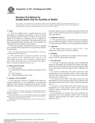
2. 7.1.5 Longitudinal Root Bend—The weld is parallel to the
longitudinal axis of the specimen which is bent so that the weld
root surface becomes the convex surface of the bent specimen
(Fig. 5).
8. Procedure
8.1 Bend the guided-bend specimens in a test jig that is
substantially in accordance with Fig. 1. Place transverse
specimens on the die member of the jig with the weld at
midspan. Place face-bend specimens with the face of the weld
directed toward the gap; place root-bend specimens with the
root of the weld directed toward the gap; and place side-bend
specimens with the side showing the greater defects toward the
gap. If no significant defects are evident, either side may be
chosen.
8.2 Any convenient means may be used for moving the
plunger with relation to the die; but it must be steady and
without any significant lateral motion. Apply the force until the
specimen conforms to a U-shape, and until a 1⁄8-in. (3.2 mm)
diameter wire cannot be inserted between the specimen and
any point on the curvature of the plunger member of the jig,
unless the specimen fails earlier.
9. Interpretation of Results
9.1 Examine the convex surface of the bent specimen for
cracks or other open defects.
9.1.1 When the test is conducted as an acceptance criterion,
the allowable crack size shall be specified by the code or
specification requiring the test.
9.1.2 When the test is conducted for informational purposes,
report the size and location of all cracks visible to the unaided
eye.
Thickness of Specimen
in. (mm)
A, in. (mm) B, in. (mm) C, in. (mm) D, in. (mm)
3⁄8 (9.5) 11⁄2 (38) 3⁄4 (19) 23⁄8 (60) 13⁄16 (30)
1⁄8 (3.2) 21⁄8 (54) 11⁄16 (27) 23⁄8 (60) 13⁄16 (30)
t 4t 2t 6t + 1⁄8 ( + 3.2) 3t + 1⁄16 ( + 1.6)
FIG. 1 Guided Bend Test Jig
t, in. (mm) T, in.
3⁄8 to 11⁄2 (9.5 to 38) t
>11⁄2 (38) See Note
NOTE—For plates over 11⁄2 in. (38 mm) thick, cut specimen into
approximately equal strips between 3⁄4 and 11⁄2 in. (19 and 38 mm) wide
and test each strip.
FIG. 2 Side-Bend Specimen for Ferrous Materials
t, in. (mm) T, in.
3⁄8 to 11⁄2 (9.5 to 38) t
>11⁄2 See Note
NOTE—For plates over 11⁄2 in. (38 mm) thick, cut specimen into
approximately equal strips between 3⁄4 and 11⁄2 in. (19 to 38 mm) wide and
test each strip.
FIG. 3 Side-Bend Specimen for Nonferrous Materials
E 190 – 92 (2003)
2
Copyright by ASTM Int'l (all rights reserved); Wed May 16 07:26:59 EDT 2007
Downloaded/printed by
Indian Institute of Technology Kanpur pursuant to License Agreement. No further reproductions authorized.
3. 10. Precision and Bias
10.1 Precision and bias statements are not made for this test
method because the test result is a nonnumerical report of
success or failure based on criteria specified in relevant
standards.
EXPLANATORY NOTES
EXPLANATORY NOTES ON BEND TEST JIG
NOTE 1—Either hardened and greased shoulders or hardened rollers
free to rotate shall be used.
NOTE 2—The shoulders or rollers shall have a minimum width of 2 in.
(50.8 mm) for the placement of the specimen.
NOTE 3—The length of the specimen shall be such that the ends will not
interfere with the seating of the specimen.
NOTE 4—The plunger shall be fitted with an appropriate base and
provisions for attachment to the testing machine; and shall be designed to
minimize deflection and misalignment.
NOTE 5—The die member shall be fitted with an appropriate base
designed to safeguard against deflection or misalignment and equipped
with means for keeping the shoulders or rollers over the midpoint and
aligned with respect to the plunger.
ASTM International takes no position respecting the validity of any patent rights asserted in connection with any item mentioned
in this standard. Users of this standard are expressly advised that determination of the validity of any such patent rights, and the risk
of infringement of such rights, are entirely their own responsibility.
This standard is subject to revision at any time by the responsible technical committee and must be reviewed every five years and
if not revised, either reapproved or withdrawn. Your comments are invited either for revision of this standard or for additional standards
and should be addressed to ASTM International Headquarters. Your comments will receive careful consideration at a meeting of the
responsible technical committee, which you may attend. If you feel that your comments have not received a fair hearing you should
make your views known to the ASTM Committee on Standards, at the address shown below.
NOTE 1—1⁄8 in. = 3.2 mm; 11⁄2 in. = 38 mm; 6 in. = 152 mm.
NOTE 2—Weld reinforcement and backing strip or backing ring, if any, shall be removed flush with the surface of the specimen. The specimen shall
be machined to a thickness, T, which must be specified in relation to t. If a recessed ring is used, this surface of the specimen may be machined to a depth
not exceeding the depth of the recess to remove the ring, except that in such cases the thickness of the finished specimen shall meet the specified
relationship to t. Do not flame-cut nonferrous material. When the original wall thickness of pipe exceeds 3⁄8 in. (9.5 mm), excess material shall be
machined from the inside surface of face-bend specimens and the outside surface of root-bend specimens. For Boiler Code nonferrous materials, see Table
QN-8, Section IX on Welding Qualifications of the ASME Boiler and Pressure Vessel Code, 1965.
FIG. 4 Transverse Face- and Root-Bend Specimens, Plate and Pipe
NOTE 1—1⁄8 in. = 3.2 mm; 11⁄2 in. = 38 mm; 6 in. = 152 mm.
NOTE 2—Weld reinforcement and backing strip, if any, shall be removed flush with the surface of the specimen. The specimen shall be machined to
a thickness, T, which must be specified in relation to t. If a recessed strip is used, this surface of the specimen may be machined to a depth not exceeding
the depth of the recess to remove the strip, except that in such cases the thickness of the finished specimen shall meet the specified relationship to t. For
Boiler Code Materials, see Table QN-8, Section IX on Welding Qualifications of the ASME Boiler and Pressure Vessel Code, 1965.
FIG. 5 Longitudinal Face- and Root-Bend Specimens, Plate
E 190 – 92 (2003)
3
Copyright by ASTM Int'l (all rights reserved); Wed May 16 07:26:59 EDT 2007
Downloaded/printed by
Indian Institute of Technology Kanpur pursuant to License Agreement. No further reproductions authorized.
4. This standard is copyrighted by ASTM International, 100 Barr Harbor Drive, PO Box C700, West Conshohocken, PA 19428-2959,
United States. Individual reprints (single or multiple copies) of this standard may be obtained by contacting ASTM at the above
address or at 610-832-9585 (phone), 610-832-9555 (fax), or service@astm.org (e-mail); or through the ASTM website
(www.astm.org).
E 190 – 92 (2003)
4
Copyright by ASTM Int'l (all rights reserved); Wed May 16 07:26:59 EDT 2007
Downloaded/printed by
Indian Institute of Technology Kanpur pursuant to License Agreement. No further reproductions authorized.