Downloaded 1,760 times
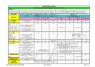
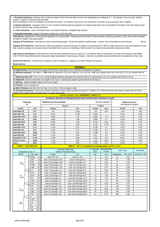
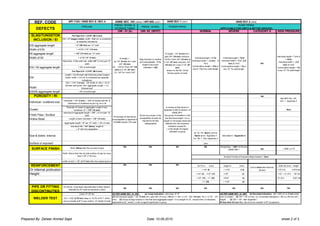

1. The document compares acceptance criteria for radiographic testing of welds according to various industry codes and standards. It lists types of defects such as cracks, incomplete penetration, and burn through. 2. Defect sizes are evaluated based on factors like weld thickness, density compared to base metal, length, and distance between defects. Some defects are unacceptable when they exceed certain sizes. 3. Charts are provided to evaluate the acceptability of rounded indications based on weld thickness and isolation from other defects. Clustered defects have stricter criteria than random defects.


