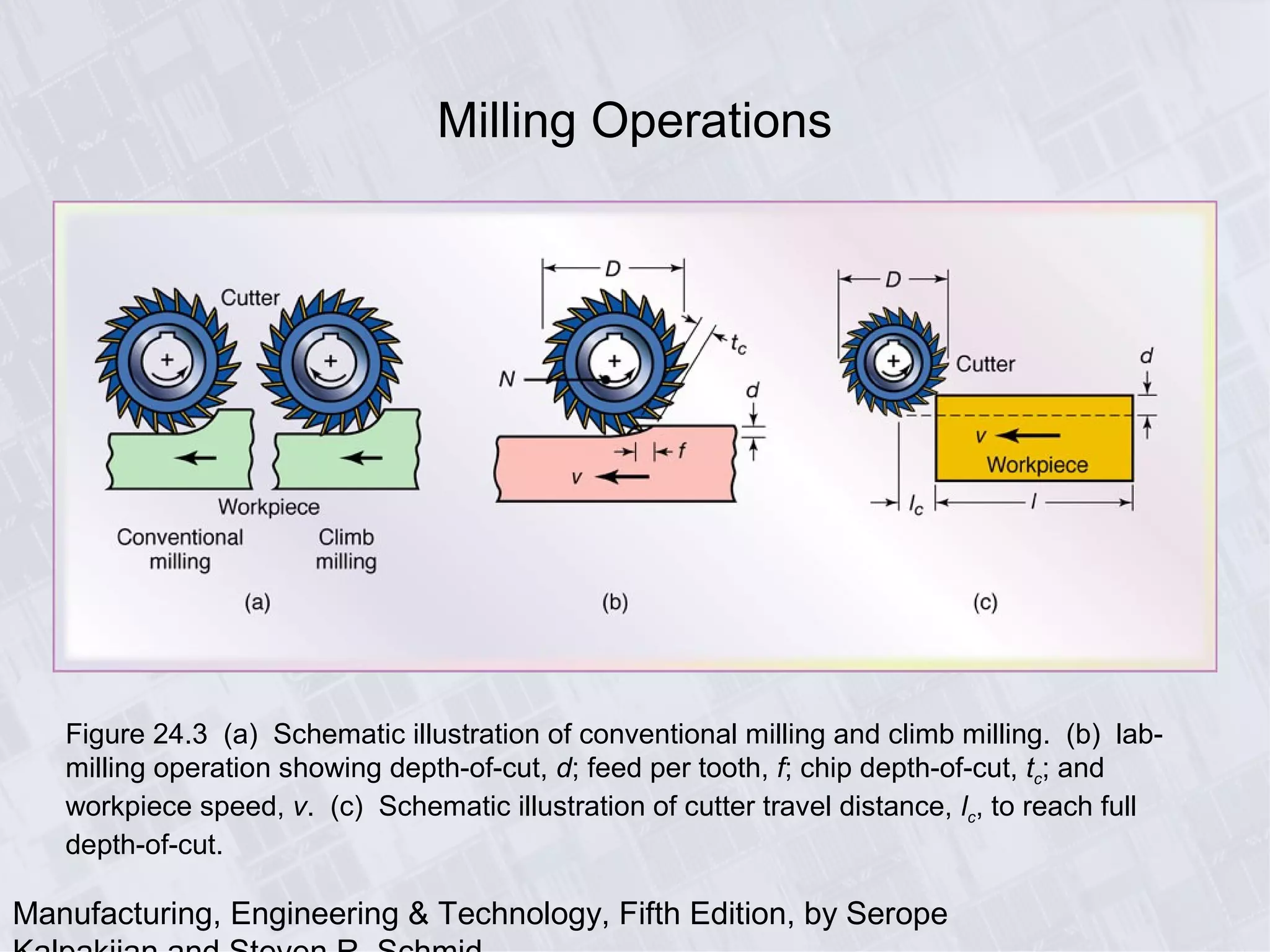
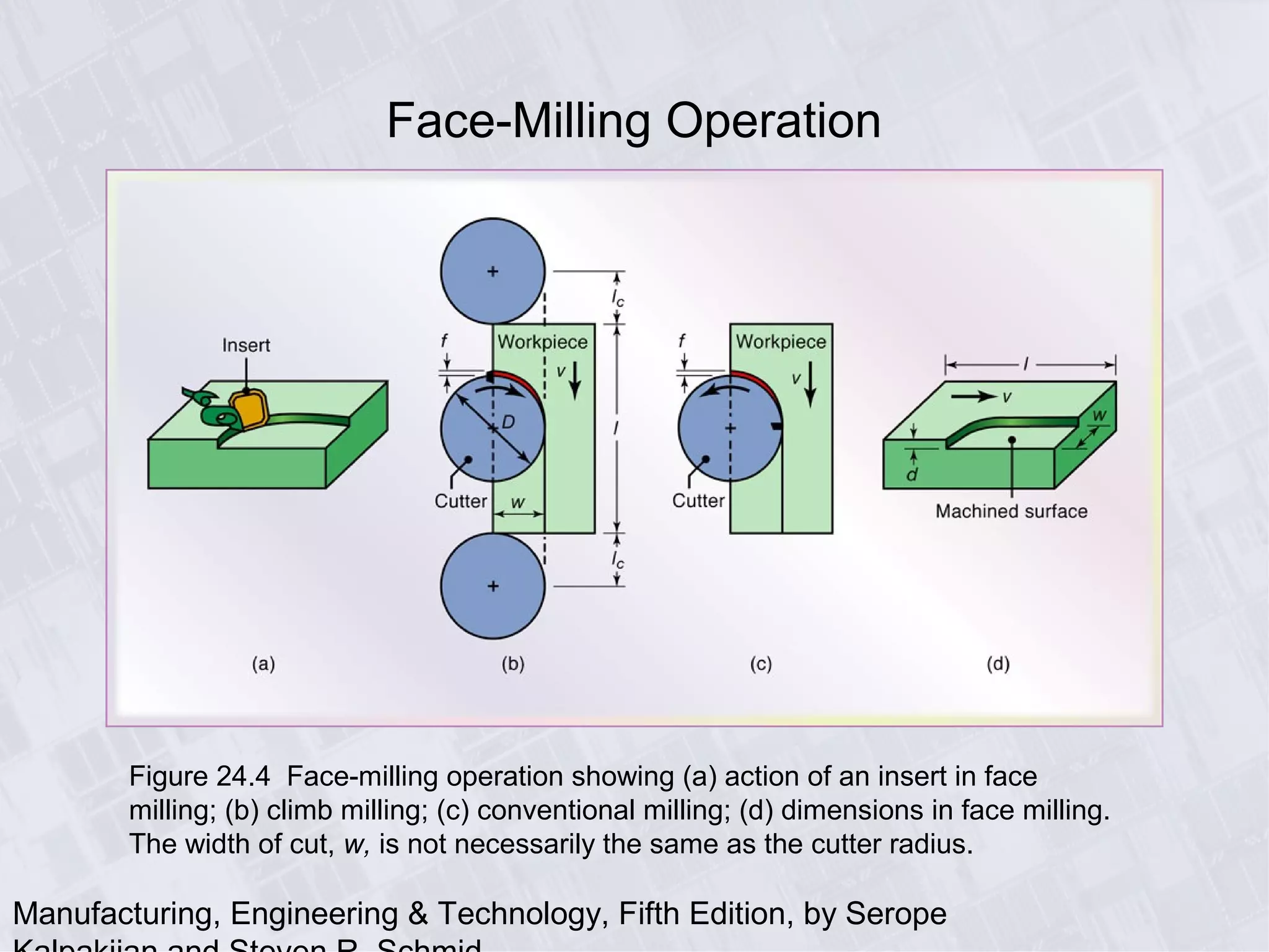
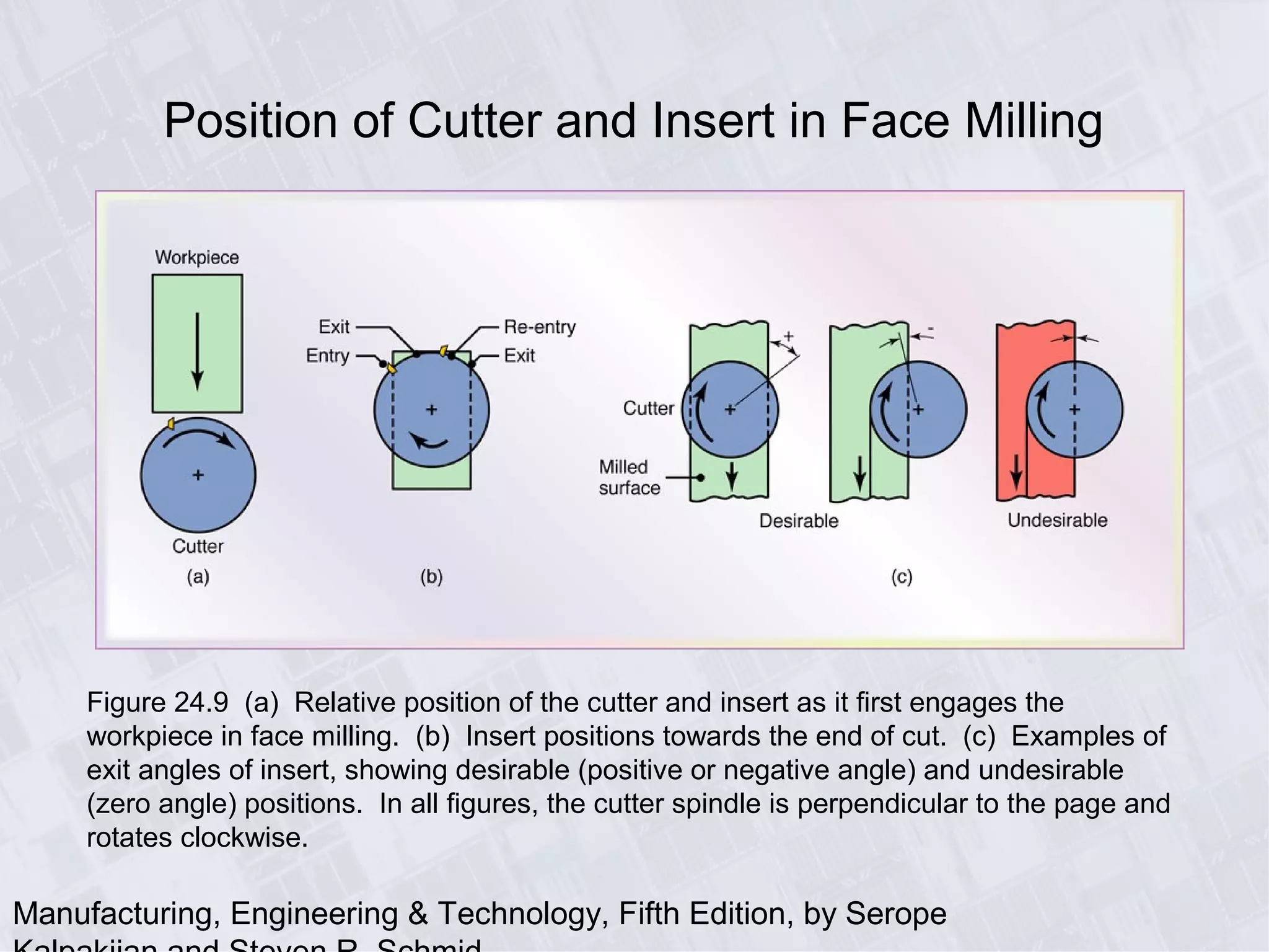
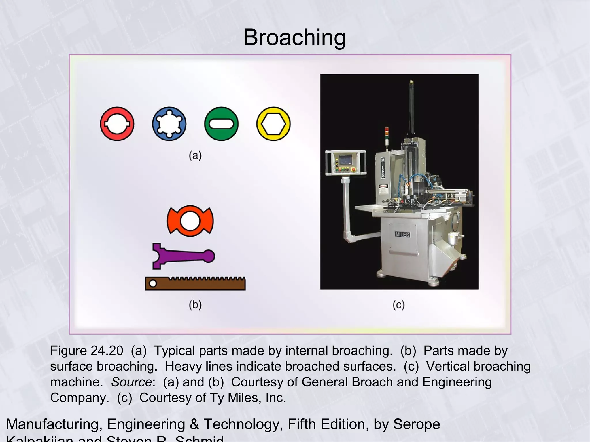
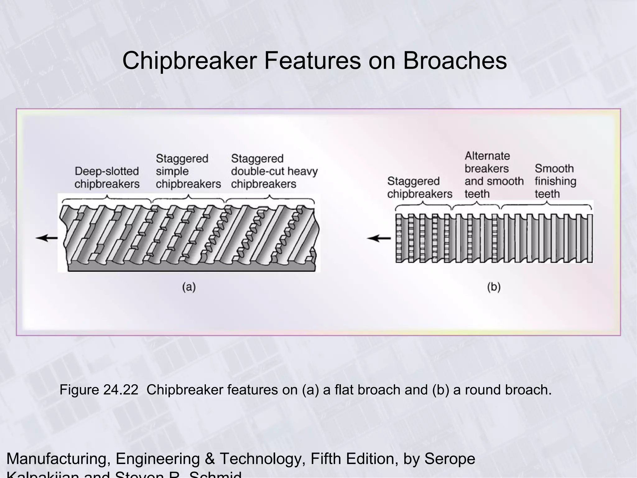
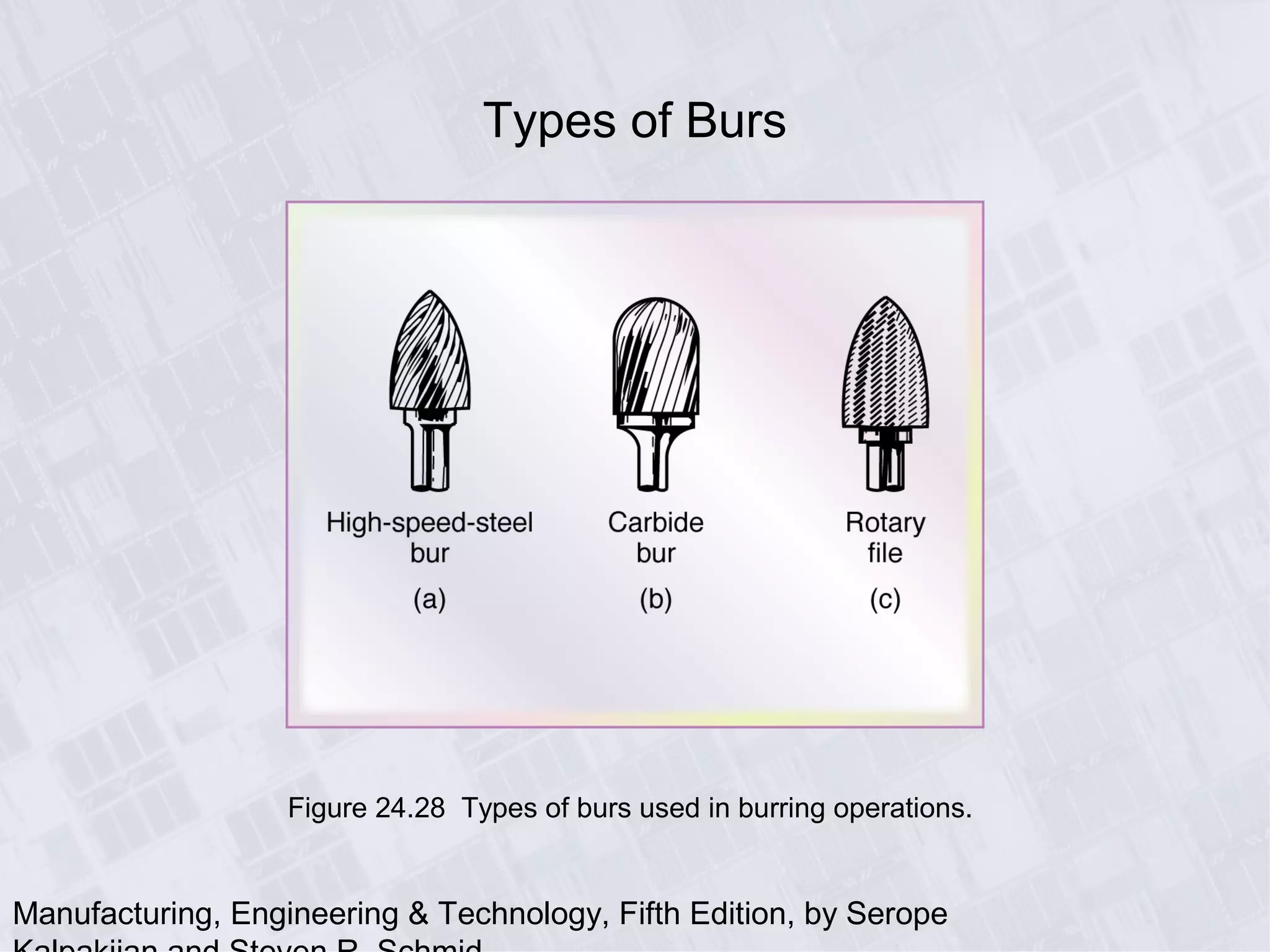
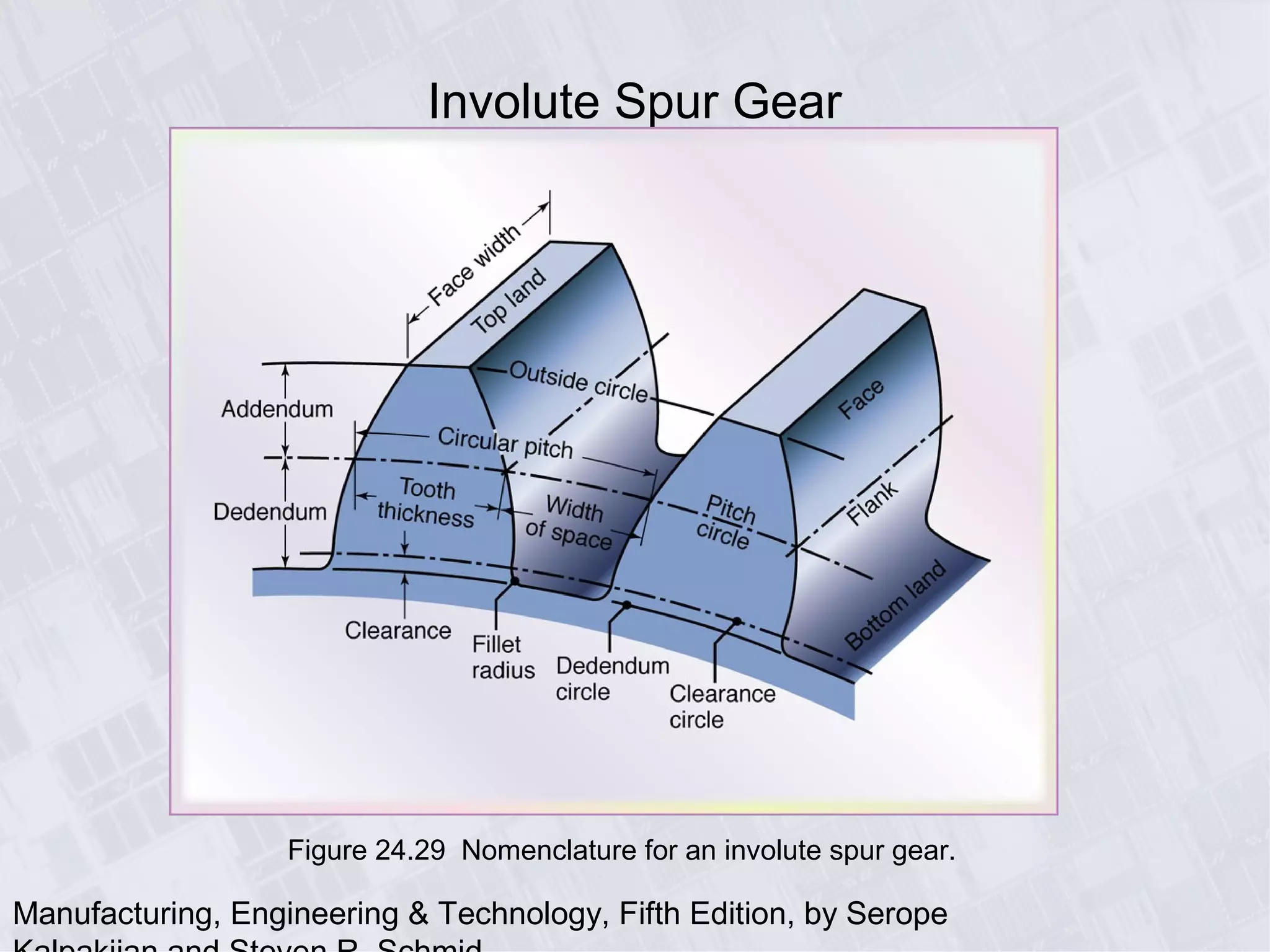
Manufacturing, Engineering & Technology, Fifth Edition, by Serope
Chapter 24
Machining Processes Used to Produce
Various Shapes: Milling, Broaching,
Sawing, and Filing; Gear Manufacturing
Manufacturing, Engineering & Technology, Fifth Edition, by Serope
Parts Made with Machining Processes of Chapter 24
Figure 24.1 Typical parts and shapes that can be produced
with the machining processes described in this chapter.
Manufacturing, Engineering & Technology, Fifth Edition, by Serope
Milling Cutters and Milling Operations
Figure 24.2 Some basic types of milling cutters and milling operations. (a) Peripheral
milling. (b) Face milling. (c) End milling. (d) Ball-end mill with indexable coated-carbide
inserts machining a cavity in a die block. (e) Milling a sculptured surface with an end mill,
using a five-axis numerical control machine. Source: (d) Courtesy of Iscar. (e) Courtesy
of The Ingersoll Milling Machine Co.
Manufacturing, Engineering & Technology, Fifth Edition, by Serope
Milling Operations
Figure 24.3 (a) Schematic illustration of conventional milling and climb milling. (b) lab-
milling operation showing depth-of-cut, d; feed per tooth, f; chip depth-of-cut, tc; and
workpiece speed, v. (c) Schematic illustration of cutter travel distance, lc, to reach full
depth-of-cut.
Manufacturing, Engineering & Technology, Fifth Edition, by Serope
Face-Milling Operation
Figure 24.4 Face-milling operation showing (a) action of an insert in face
milling; (b) climb milling; (c) conventional milling; (d) dimensions in face milling.
The width of cut, w, is not necessarily the same as the cutter radius.
Manufacturing, Engineering & Technology, Fifth Edition, by Serope
Summary of Peripheral Milling Parameters and
Formulas
Manufacturing, Engineering & Technology, Fifth Edition, by Serope
Face-Milling Cutter with Indexable Inserts
Figure 24.5 A face-milling cutter with indexable inserts.
Source: Courtesy of Ingersoll Cutting Tool Company.
Manufacturing, Engineering & Technology, Fifth Edition, by Serope
Effect of Insert
Shape on Feed
Marks on a Face-
Milled Surface
Figure 24.6 Schematic illustration of the effect of insert shape on feed marks on a face-
milled surface: (a) small corner radius, (b) corner flat on insert, and (c) wiper, consisting of
small radius followed by a large radius which leaves smoother feed marks. (d) Feed marks
due to various insert shapes.
Manufacturing, Engineering & Technology, Fifth Edition, by Serope
Face-Milling Cutter
Figure 24.7 Terminology for a face-milling cutter.
Manufacturing, Engineering & Technology, Fifth Edition, by Serope
Effect of Lead Angle on Undeformed Chip
Thickness in Face Milling
Figure 24.8 The effect of the lead angle on the undeformed chip thickness in face
milling. Note that as the lead angle increases, the chip thickness decreases, but
the length of contact (i.e., chip width) increases. The edges of the insert must be
sufficiently large to accommodate the contact length increase.
Manufacturing, Engineering & Technology, Fifth Edition, by Serope
Position of Cutter and Insert in Face Milling
Figure 24.9 (a) Relative position of the cutter and insert as it first engages the
workpiece in face milling. (b) Insert positions towards the end of cut. (c) Examples of
exit angles of insert, showing desirable (positive or negative angle) and undesirable
(zero angle) positions. In all figures, the cutter spindle is perpendicular to the page and
rotates clockwise.
Manufacturing, Engineering & Technology, Fifth Edition, by Serope
Ball Nose End Mills
Figure 24.10 Ball nose end mills.
These cutters are able to produce
elaborate contours and are often
used in the machining of dies and
molds. (See also Fig. 24.2d.)
Source: Courtesy of Dijet, Inc.
Manufacturing, Engineering & Technology, Fifth Edition, by Serope
Cutters
Figure 24.11 Cutters for (a) straddle milling, (b) form
milling, (c) slotting, and (d) slitting with a milling cutter.
Manufacturing, Engineering & Technology, Fifth Edition, by Serope
T-Slot Cutting and Shell Mill
Figure 24.12 (a) T-slot cutting with a milling cutter. (b) A shell mill.
Manufacturing, Engineering & Technology, Fifth Edition, by Serope
General Recommendations for Milling Operations
Manufacturing, Engineering & Technology, Fifth Edition, by Serope
Troubleshooting Guide for Milling Operations
Manufacturing, Engineering & Technology, Fifth Edition, by Serope
Machined Surface Features in Face Milling
Figure 24.13 Machined surface features in face milling. See also Fig. 24.6.
Manufacturing, Engineering & Technology, Fifth Edition, by Serope
Edge Defects in Face Milling
Figure 24.14 Edge defects in face milling: (a) burr formation along
workpiece edge, (b) breakout along workpiece edge, and (c) how it can be
avoided by increasing the lead angle (see also last row in Table 24.4).
Manufacturing, Engineering & Technology, Fifth Edition, by Serope
Column-and-Knee Type Milling Machines
Figure 24.15 Schematic illustration of (a) a horizontal-spindle column-and-
knee type milling machine and (b) vertical-spindle column-and-knee type
milling machine. Source: After G. Boothroyd.
Manufacturing, Engineering & Technology, Fifth Edition, by Serope
CNC Vertical-Spindle Milling Machine
Figure 24.17 A computer numerical-control (CNC) vertical-spindle milling
machine. This machine is one of the most versatile machine tools. The
original vertical-spindle milling machine iused in job shops is still referred
to as a “Bridgeport”, after its manufacturer in Bridgeport, Connecticut.
Source: Courtesy of Bridgeport Machines Dibision, Textron Inc.
Manufacturing, Engineering & Technology, Fifth Edition, by Serope
Five-Axis Profile Milling Machine
Figure 24.18 Schematic illustration of a five-axis profile milling machine. Note that
there are three principal linear and two angular movements of machine components.
Manufacturing, Engineering & Technology, Fifth Edition, by Serope
Parts Made on a Planer
Figure 24,19 Typical parts that can be made on a planer.
Manufacturing, Engineering & Technology, Fifth Edition, by Serope
Broaching
Figure 24.20 (a) Typical parts made by internal broaching. (b) Parts made by
surface broaching. Heavy lines indicate broached surfaces. (c) Vertical broaching
machine. Source: (a) and (b) Courtesy of General Broach and Engineering
Company. (c) Courtesy of Ty Miles, Inc.
Manufacturing, Engineering & Technology, Fifth Edition, by Serope
Broach Geometry
Figure 24.21 (a) Cutting action of a broach showing various features.
(b) Terminology for a broach.
Manufacturing, Engineering & Technology, Fifth Edition, by Serope
Chipbreaker Features on Broaches
Figure 24.22 Chipbreaker features on (a) a flat broach and (b) a round broach.
Manufacturing, Engineering & Technology, Fifth Edition, by Serope
Pull-Types Internal Broach
Figure 24.23 Terminology for a pull-type internal broach used for enlarging long holes.
Manufacturing, Engineering & Technology, Fifth Edition, by Serope
Part with Internal Splines Made by Broaching
Figure 24.24 Example of a part with internal splines produced by broaching.
Manufacturing, Engineering & Technology, Fifth Edition, by Serope
Sawing Operations
Figure 24.25 Examples of various sawing operations.
Manufacturing, Engineering & Technology, Fifth Edition, by Serope
Saw Teeth
Figure 24.26 (a) Terminology for saw teeth. (b) Types of tooth sets on saw teeth
staggered to provide clearance for the saw blade to prevent binding during sawing.
Figure 24.27 (a) High-
speed-steel teeth welded
on a steel blade. (b)
Carbide inserts brazed to
blade teeth.
Manufacturing, Engineering & Technology, Fifth Edition, by Serope
Types of Burs
Figure 24.28 Types of burs used in burring operations.
Manufacturing, Engineering & Technology, Fifth Edition, by Serope
Involute Spur Gear
Figure 24.29 Nomenclature for an involute spur gear.
Manufacturing, Engineering & Technology, Fifth Edition, by Serope
Gear Generating
with Various
Cutters
Figure 24.30 (a) Producing gear
teeth on a blank by form cutting.
(b) Schematic illustration of gear
generating with a pinion-shaped
gear cutter. (c) and (d) Gear
generating on a gear shaper
using a pinion-shaped cutter.
Note that the cutter reciprocates
vertically. (e) Gear generating
with rack-shaped cutter. Source:
(d) Schafer Gear Works, Inc.
Manufacturing, Engineering & Technology, Fifth Edition, by Serope
Hobbing
Figure 24.31 (a) Schematic illustration of gear cutting with a hob. (b) Production of
worm gear through hobbing. Source: Courtesy of Schafer Gear Works, Inc.
Manufacturing, Engineering & Technology, Fifth Edition, by Serope
Bevel Gears
Figure 24.32 (a) Cutting a straight bevel-gear blank with two cutter. (b)
Cutting a helical bevel gear. Source: Courtesy of Schafer Gear Works, Inc.
Manufacturing, Engineering & Technology, Fifth Edition, by Serope
Finishing Gears
by Grinding
Figure 24.33 Finishing
gears by grinding: (a)
form grinding with shaped
grinding wheels; (b)
grinding by generating
with two wheels.
Manufacturing, Engineering & Technology, Fifth Edition, by Serope
Gear Manufacturing Cost as a Function of Gear Quantity
Figure 24.34 Gear manufacturing cost as a function of gear quality.
The numbers along the vertical lines indicate tolerances.

GEARS

  • 1.
    Manufacturing, Engineering &Technology, Fifth Edition, by Serope Chapter 24 Machining Processes Used to Produce Various Shapes: Milling, Broaching, Sawing, and Filing; Gear Manufacturing
  • 2.
    Manufacturing, Engineering &Technology, Fifth Edition, by Serope Parts Made with Machining Processes of Chapter 24 Figure 24.1 Typical parts and shapes that can be produced with the machining processes described in this chapter.
  • 3.
    Manufacturing, Engineering &Technology, Fifth Edition, by Serope Milling Cutters and Milling Operations Figure 24.2 Some basic types of milling cutters and milling operations. (a) Peripheral milling. (b) Face milling. (c) End milling. (d) Ball-end mill with indexable coated-carbide inserts machining a cavity in a die block. (e) Milling a sculptured surface with an end mill, using a five-axis numerical control machine. Source: (d) Courtesy of Iscar. (e) Courtesy of The Ingersoll Milling Machine Co.
  • 4.
    Manufacturing, Engineering &Technology, Fifth Edition, by Serope Milling Operations Figure 24.3 (a) Schematic illustration of conventional milling and climb milling. (b) lab- milling operation showing depth-of-cut, d; feed per tooth, f; chip depth-of-cut, tc; and workpiece speed, v. (c) Schematic illustration of cutter travel distance, lc, to reach full depth-of-cut.
  • 5.
    Manufacturing, Engineering &Technology, Fifth Edition, by Serope Face-Milling Operation Figure 24.4 Face-milling operation showing (a) action of an insert in face milling; (b) climb milling; (c) conventional milling; (d) dimensions in face milling. The width of cut, w, is not necessarily the same as the cutter radius.
  • 6.
    Manufacturing, Engineering &Technology, Fifth Edition, by Serope Summary of Peripheral Milling Parameters and Formulas
  • 7.
    Manufacturing, Engineering &Technology, Fifth Edition, by Serope Face-Milling Cutter with Indexable Inserts Figure 24.5 A face-milling cutter with indexable inserts. Source: Courtesy of Ingersoll Cutting Tool Company.
  • 8.
    Manufacturing, Engineering &Technology, Fifth Edition, by Serope Effect of Insert Shape on Feed Marks on a Face- Milled Surface Figure 24.6 Schematic illustration of the effect of insert shape on feed marks on a face- milled surface: (a) small corner radius, (b) corner flat on insert, and (c) wiper, consisting of small radius followed by a large radius which leaves smoother feed marks. (d) Feed marks due to various insert shapes.
  • 9.
    Manufacturing, Engineering &Technology, Fifth Edition, by Serope Face-Milling Cutter Figure 24.7 Terminology for a face-milling cutter.
  • 10.
    Manufacturing, Engineering &Technology, Fifth Edition, by Serope Effect of Lead Angle on Undeformed Chip Thickness in Face Milling Figure 24.8 The effect of the lead angle on the undeformed chip thickness in face milling. Note that as the lead angle increases, the chip thickness decreases, but the length of contact (i.e., chip width) increases. The edges of the insert must be sufficiently large to accommodate the contact length increase.
  • 11.
    Manufacturing, Engineering &Technology, Fifth Edition, by Serope Position of Cutter and Insert in Face Milling Figure 24.9 (a) Relative position of the cutter and insert as it first engages the workpiece in face milling. (b) Insert positions towards the end of cut. (c) Examples of exit angles of insert, showing desirable (positive or negative angle) and undesirable (zero angle) positions. In all figures, the cutter spindle is perpendicular to the page and rotates clockwise.
  • 12.
    Manufacturing, Engineering &Technology, Fifth Edition, by Serope Ball Nose End Mills Figure 24.10 Ball nose end mills. These cutters are able to produce elaborate contours and are often used in the machining of dies and molds. (See also Fig. 24.2d.) Source: Courtesy of Dijet, Inc.
  • 13.
    Manufacturing, Engineering &Technology, Fifth Edition, by Serope Cutters Figure 24.11 Cutters for (a) straddle milling, (b) form milling, (c) slotting, and (d) slitting with a milling cutter.
  • 14.
    Manufacturing, Engineering &Technology, Fifth Edition, by Serope T-Slot Cutting and Shell Mill Figure 24.12 (a) T-slot cutting with a milling cutter. (b) A shell mill.
  • 15.
    Manufacturing, Engineering &Technology, Fifth Edition, by Serope General Recommendations for Milling Operations
  • 16.
    Manufacturing, Engineering &Technology, Fifth Edition, by Serope Troubleshooting Guide for Milling Operations
  • 17.
    Manufacturing, Engineering &Technology, Fifth Edition, by Serope Machined Surface Features in Face Milling Figure 24.13 Machined surface features in face milling. See also Fig. 24.6.
  • 18.
    Manufacturing, Engineering &Technology, Fifth Edition, by Serope Edge Defects in Face Milling Figure 24.14 Edge defects in face milling: (a) burr formation along workpiece edge, (b) breakout along workpiece edge, and (c) how it can be avoided by increasing the lead angle (see also last row in Table 24.4).
  • 19.
    Manufacturing, Engineering &Technology, Fifth Edition, by Serope Column-and-Knee Type Milling Machines Figure 24.15 Schematic illustration of (a) a horizontal-spindle column-and- knee type milling machine and (b) vertical-spindle column-and-knee type milling machine. Source: After G. Boothroyd.
  • 20.
    Manufacturing, Engineering &Technology, Fifth Edition, by Serope CNC Vertical-Spindle Milling Machine Figure 24.17 A computer numerical-control (CNC) vertical-spindle milling machine. This machine is one of the most versatile machine tools. The original vertical-spindle milling machine iused in job shops is still referred to as a “Bridgeport”, after its manufacturer in Bridgeport, Connecticut. Source: Courtesy of Bridgeport Machines Dibision, Textron Inc.
  • 21.
    Manufacturing, Engineering &Technology, Fifth Edition, by Serope Five-Axis Profile Milling Machine Figure 24.18 Schematic illustration of a five-axis profile milling machine. Note that there are three principal linear and two angular movements of machine components.
  • 22.
    Manufacturing, Engineering &Technology, Fifth Edition, by Serope Parts Made on a Planer Figure 24,19 Typical parts that can be made on a planer.
  • 23.
    Manufacturing, Engineering &Technology, Fifth Edition, by Serope Broaching Figure 24.20 (a) Typical parts made by internal broaching. (b) Parts made by surface broaching. Heavy lines indicate broached surfaces. (c) Vertical broaching machine. Source: (a) and (b) Courtesy of General Broach and Engineering Company. (c) Courtesy of Ty Miles, Inc.
  • 24.
    Manufacturing, Engineering &Technology, Fifth Edition, by Serope Broach Geometry Figure 24.21 (a) Cutting action of a broach showing various features. (b) Terminology for a broach.
  • 25.
    Manufacturing, Engineering &Technology, Fifth Edition, by Serope Chipbreaker Features on Broaches Figure 24.22 Chipbreaker features on (a) a flat broach and (b) a round broach.
  • 26.
    Manufacturing, Engineering &Technology, Fifth Edition, by Serope Pull-Types Internal Broach Figure 24.23 Terminology for a pull-type internal broach used for enlarging long holes.
  • 27.
    Manufacturing, Engineering &Technology, Fifth Edition, by Serope Part with Internal Splines Made by Broaching Figure 24.24 Example of a part with internal splines produced by broaching.
  • 28.
    Manufacturing, Engineering &Technology, Fifth Edition, by Serope Sawing Operations Figure 24.25 Examples of various sawing operations.
  • 29.
    Manufacturing, Engineering &Technology, Fifth Edition, by Serope Saw Teeth Figure 24.26 (a) Terminology for saw teeth. (b) Types of tooth sets on saw teeth staggered to provide clearance for the saw blade to prevent binding during sawing. Figure 24.27 (a) High- speed-steel teeth welded on a steel blade. (b) Carbide inserts brazed to blade teeth.
  • 30.
    Manufacturing, Engineering &Technology, Fifth Edition, by Serope Types of Burs Figure 24.28 Types of burs used in burring operations.
  • 31.
    Manufacturing, Engineering &Technology, Fifth Edition, by Serope Involute Spur Gear Figure 24.29 Nomenclature for an involute spur gear.
  • 32.
    Manufacturing, Engineering &Technology, Fifth Edition, by Serope Gear Generating with Various Cutters Figure 24.30 (a) Producing gear teeth on a blank by form cutting. (b) Schematic illustration of gear generating with a pinion-shaped gear cutter. (c) and (d) Gear generating on a gear shaper using a pinion-shaped cutter. Note that the cutter reciprocates vertically. (e) Gear generating with rack-shaped cutter. Source: (d) Schafer Gear Works, Inc.
  • 33.
    Manufacturing, Engineering &Technology, Fifth Edition, by Serope Hobbing Figure 24.31 (a) Schematic illustration of gear cutting with a hob. (b) Production of worm gear through hobbing. Source: Courtesy of Schafer Gear Works, Inc.
  • 34.
    Manufacturing, Engineering &Technology, Fifth Edition, by Serope Bevel Gears Figure 24.32 (a) Cutting a straight bevel-gear blank with two cutter. (b) Cutting a helical bevel gear. Source: Courtesy of Schafer Gear Works, Inc.
  • 35.
    Manufacturing, Engineering &Technology, Fifth Edition, by Serope Finishing Gears by Grinding Figure 24.33 Finishing gears by grinding: (a) form grinding with shaped grinding wheels; (b) grinding by generating with two wheels.
  • 36.
    Manufacturing, Engineering &Technology, Fifth Edition, by Serope Gear Manufacturing Cost as a Function of Gear Quantity Figure 24.34 Gear manufacturing cost as a function of gear quality. The numbers along the vertical lines indicate tolerances.