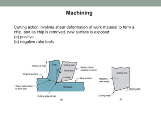
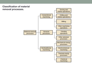
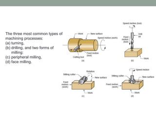
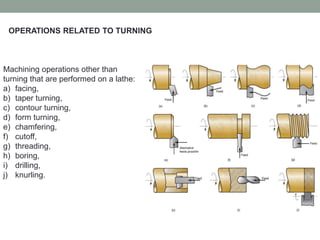
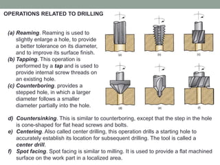
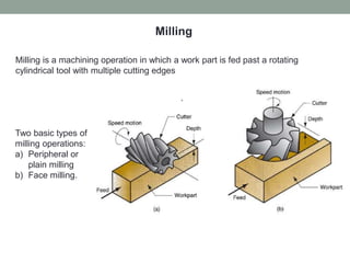
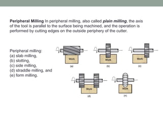
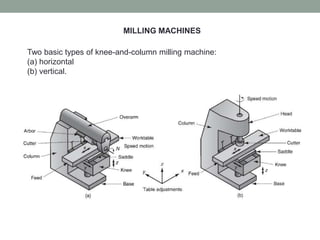
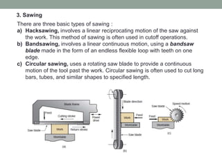
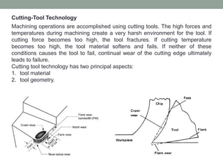
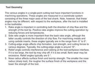
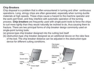
2. Cutting action involves shear deformation of work material to form a
chip, and as chip is removed, new surface is exposed:
(a) positive
(b) negative rake tools
Machining
5. The three most common types of
machining processes:
(a) turning,
(b) drilling, and two forms of
milling:
(c) peripheral milling,
(d) face milling.
6. Machining operations other than
turning that are performed on a lathe:
a) facing,
b) taper turning,
c) contour turning,
d) form turning,
e) chamfering,
f) cutoff,
g) threading,
h) boring,
i) drilling,
j) knurling.
OPERATIONS RELATED TO TURNING
7. Four workholding methods
used in lathes:
a) mounting the work between
centers using a dog,
b) three-jaw chuck,
c) collet,
d) faceplate for noncylindrical
work parts.
THE ENGINE LATHE
8. (a) Reaming. Reaming is used to
slightly enlarge a hole, to provide
a better tolerance on its diameter,
and to improve its surface finish.
(b) Tapping. This operation is
performed by a tap and is used to
provide internal screw threads on
an existing hole.
(c) Counterboring. provides a
stepped hole, in which a larger
diameter follows a smaller
diameter partially into the hole.
d) Countersinking. This is similar to counterboring, except that the step in the hole
is cone-shaped for flat head screws and bolts.
e) Centering. Also called center drilling, this operation drills a starting hole to
accurately establish its location for subsequent drilling. The tool is called a
center drill.
f) Spot facing. Spot facing is similar to milling. It is used to provide a flat machined
surface on the work part in a localized area.
OPERATIONS RELATED TO DRILLING
9. Milling is a machining operation in which a work part is fed past a rotating
cylindrical tool with multiple cutting edges
Milling
Two basic types of
milling operations:
a) Peripheral or
plain milling
b) Face milling.
10. Peripheral Milling In peripheral milling, also called plain milling, the axis
of the tool is parallel to the surface being machined, and the operation is
performed by cutting edges on the outside periphery of the cutter.
Peripheral milling:
(a) slab milling,
(b) slotting,
(c) side milling,
(d) straddle milling, and
(e) form milling.
11. Face Milling In face milling, the axis of the cutter is perpendicular to the
surface being milled, and machining is performed by cutting edges on
both the end and outside periphery of the cutter
Face milling:
(a) Conventional face milling,
(b) Partial face milling,
(c) End milling,
(d) Profile milling,
(e) Pocket milling,
(f) Surface contouring.
13. Other Machining Operations
1. Shaping and Planing
In shaping, the speed motion is accomplished by moving the cutting tool;
while in planing, the speed motion is accomplished by moving the work
part.
14. Broaching is performed using a multiple teeth cutting tool by moving the tool
linearly relative to the work in the direction of the tool axis.
2. Broaching
The basic function of a broaching machine is to provide a precise linear
motion of the tool past a stationary work position.
There are two principal types of broaching: external and internal. External
broaching is performed on the outside surface of the work to create a certain
cross-sectional shape on the surface. Internal broaching is accomplished on
the internal surface of a hole in the part.
15. There are three basic types of sawing :
a) Hacksawing, involves a linear reciprocating motion of the saw against
the work. This method of sawing is often used in cutoff operations.
b) Bandsawing, involves a linear continuous motion, using a bandsaw
blade made in the form of an endless flexible loop with teeth on one
edge.
c) Circular sawing, uses a rotating saw blade to provide a continuous
motion of the tool past the work. Circular sawing is often used to cut long
bars, tubes, and similar shapes to specified length.
3. Sawing
16. Cutting-Tool Technology
Machining operations are accomplished using cutting tools. The high forces and
temperatures during machining create a very harsh environment for the tool. If
cutting force becomes too high, the tool fractures. If cutting temperature
becomes too high, the tool material softens and fails. If neither of these
conditions causes the tool to fail, continual wear of the cutting edge ultimately
leads to failure.
Cutting tool technology has two principal aspects:
1. tool material
2. tool geometry.
17. Tool Materials
The three modes of tool failure allow us to identify three important properties
required in a tool material:
Toughness. To avoid fracture failure, the tool material must possess high
toughness. Toughness is the capacity of a material to absorb energy without
failing. It is usually characterized by a combination of strength and ductility in
the material.
Hot hardness. Hot hardness is the ability of a material to retain its hardness
at high temperatures. This is required because of the high-temperature
environment in which the tool operates.
Wear resistance. Hardness is the single most important property needed to
resist abrasive wear. All cutting-tool materials must be hard. However, wear
resistance in metal cutting depends on more than just tool hardness,
because of the other tool-wear mechanisms. Other characteristics affecting
wear resistance include surface finish on the tool (a smoother surface
means a lower coefficient of friction), chemistry of tool and work materials,
and whether a cutting fluid is used.
18. Typical hot hardness relationships for selected tool materials. Plain carbon steel
shows a rapid loss of hardness as temperature increases. Highspeed steel is
substantially better, while cemented carbides and ceramics are significantly
harderat elevated temperatures.
19. Tool Geometry
The various angles in a single-point cutting tool have important functions in
machining operations. These angles are measured in a coordinate system
consisting of the three major axes of the tool shank. Note, however, that these
angles may be different, with respect to the workpiece, after the tool is installed
in the toolholder.
1. Rake angle is important in controlling both the direction of chip flow and the
strength of the tool tip. Positive rake angles improve the cutting operation by
reducing forces and temperatures.
2. Side rake angle is more important than the back rake angle, although the
latter usually controls the direction of chip flow. For machining metals and
using carbide inserts, these angles typically are in the range from -5° to 5°.
3. Cutting-edge angle affects chip formation, tool strength, and cutting forces to
various degrees. Typically, the cutting-edge angle is around 15°.
4. Relief angle controls interference and rubbing at the tool-workpiece interface.
If it is too large, the tool tip may chip off; if it is too small, flank wear may be
excessive. Relief angles typically are 5 °.
5. Nose radius affects surface finish and tool-tip strength. The smaller the nose
radius (sharp tool), the rougher the surface finish of the workpiece and the
lower the strength of the tool.
20.
21.
22. Chip Breakers
Chip disposal is a problem that is often encountered in turning and other continuous
operations. Long, stringy chips are often generated, especially when turning ductile
materials at high speeds. These chips cause a hazard to the machine operator and
the work part finish, and they interfere with automatic operation of the turning
process. Chip breakers are frequently used with single-point tools to force the chips
to curl more tightly than they would naturally be inclined to do, thus causing them to
fracture. There are two principal forms of chip breaker design commonly used on
single-point turning tools:
(a) groove-type chip breaker designed into the cutting tool itself
(b) obstruction-type chip breaker designed as an additional device on the rake face
of the tool. The chip breaker distance can be adjusted in the obstruction-type
device for different cutting conditions.