Downloaded 106 times
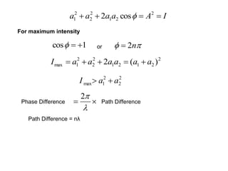
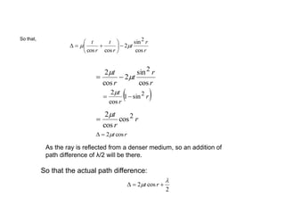
![Spacing between successive rings
This shows that the spacing decreases with increase in the order of the rings.
]1[1 nnkDD nn
]12[12 kDD
]23[23 kDD
]34[34 kDD](https://image.slidesharecdn.com/1interference-150605121908-lva1-app6891/85/1-interference-42-320.jpg)
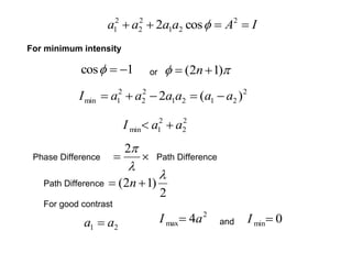
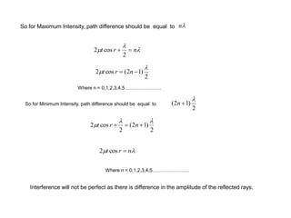
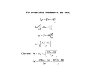
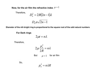
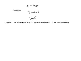
![For Air film,
RnD airn 4][ 2
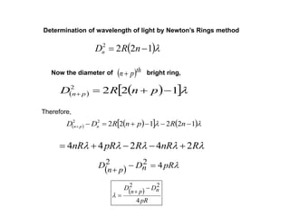
Determination of refractive index of unknown liquid by Newton’s Rings method
For unknown liquid with refractive index m
m
Rn
D liquidn
4
][ 2
liquidn
airn
D
D
][
][
2
2
m](https://image.slidesharecdn.com/1interference-150605121908-lva1-app6891/85/1-interference-44-320.jpg)

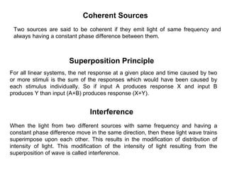
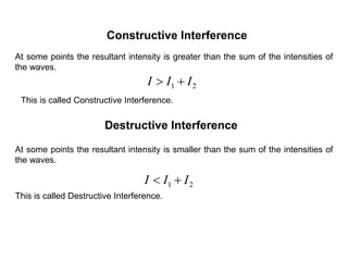
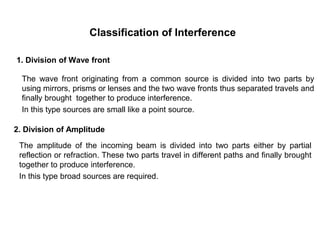
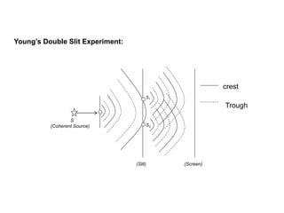
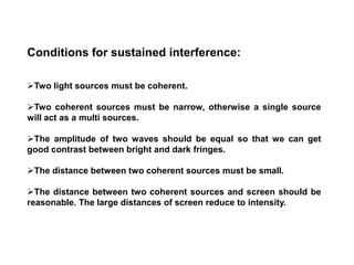
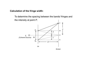
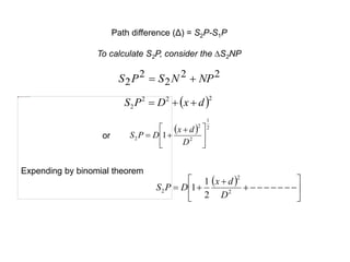
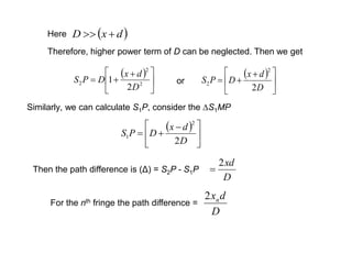
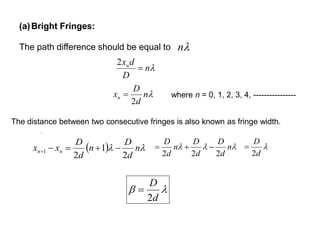
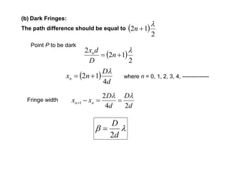
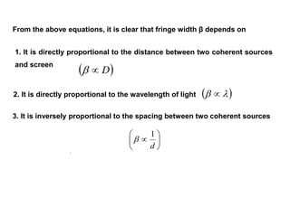
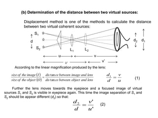
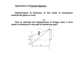
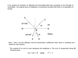
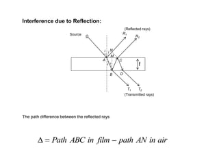
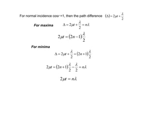
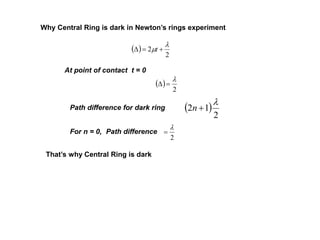
- Interference occurs when two light waves superimpose, resulting in a modification of the intensity of light. This occurs when two coherent sources emit light of the same frequency and constant phase difference. - Constructive interference occurs when the path difference between the waves is equal to an integer multiple of the wavelength, resulting in brighter fringes. Destructive interference occurs when the path difference is an odd integer multiple of half the wavelength, resulting in darker fringes. - In Young's double slit experiment, the fringe width is directly proportional to the wavelength and distance between the slits and screen, and inversely proportional to the slit separation. The fringe width can be used to determine properties like the thickness of thin sheets.