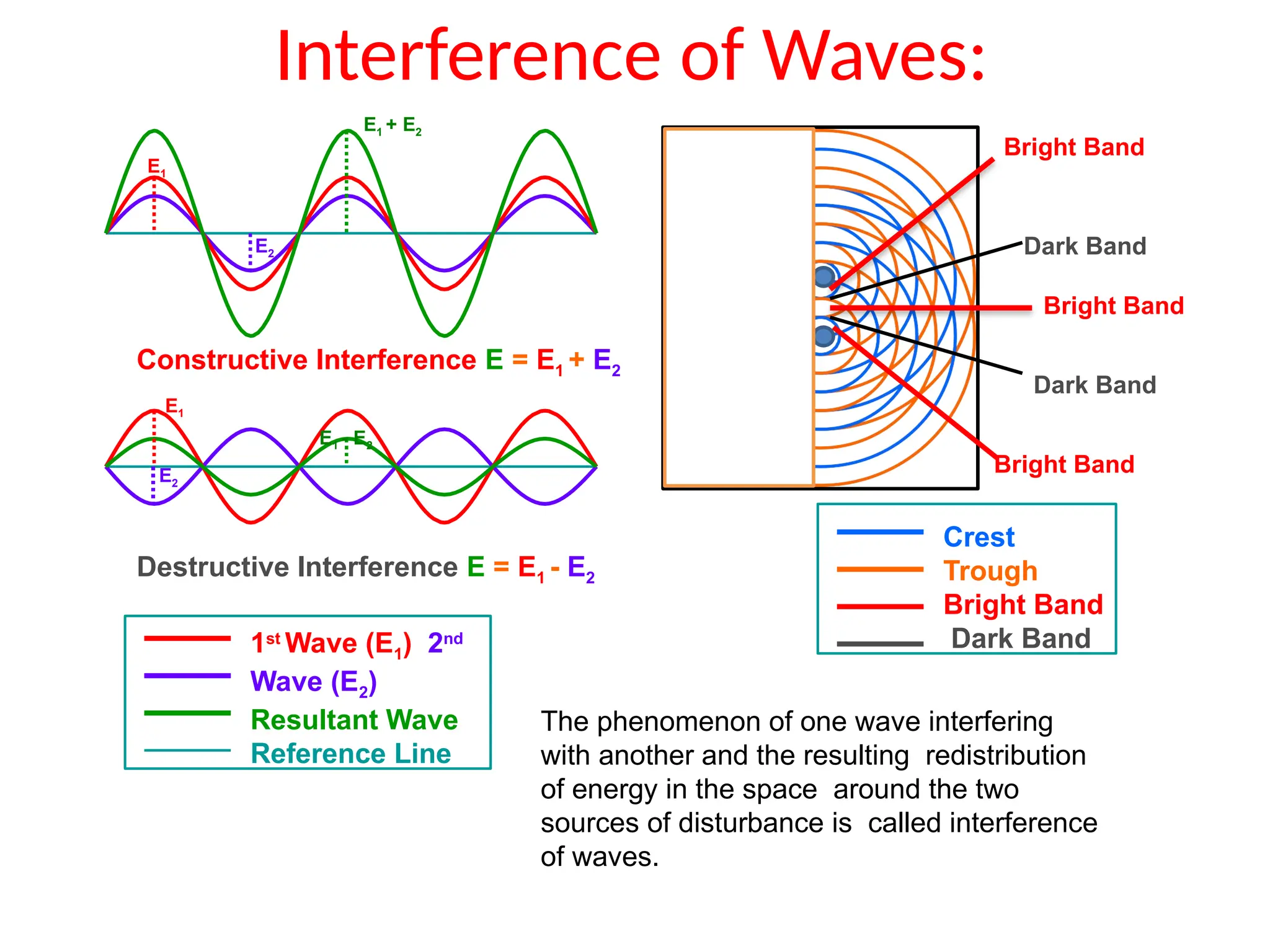
The document discusses wave optics concepts, including Huygens’ principle, wavefronts, and the laws of reflection and refraction, as well as phenomena like interference and diffraction. It explains how coherent sources produce constructive and destructive interference, gives examples such as the double-slit experiment, and addresses light polarization and Brewster's law. The document concludes with practical applications of polaroids and the various uses of polarized light in everyday technology.
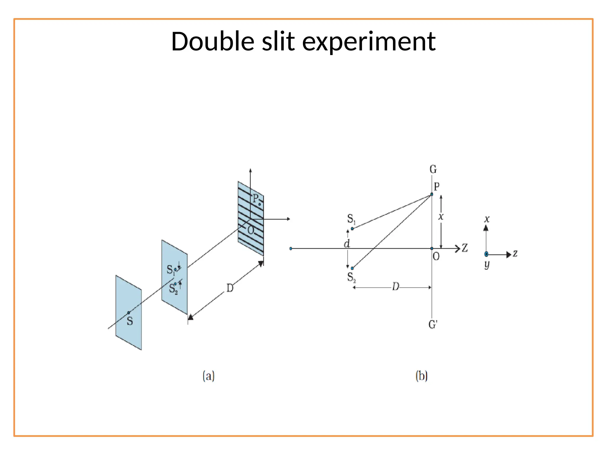
![Path difference
The waves from S1 and S2 reach the point P with
Path difference ∆ = S2P – S1P
S2P2
– S1P2
= [D2
+ {x + (d/2)}2
] - [D2
+ {x - (d/2)}2
]
(S2P – S1P) (S2P + S1P) = 2 x d
∆ = x d / D](https://image.slidesharecdn.com/waveoptics-241122070443-b538699c/75/Wave-Optics-class-XII-SCIENCE-PROJECT-FILE-14-2048.jpg)