Download as PDF, PPTX
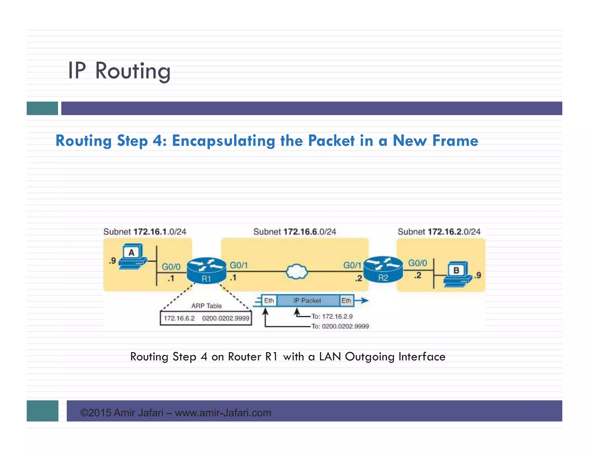
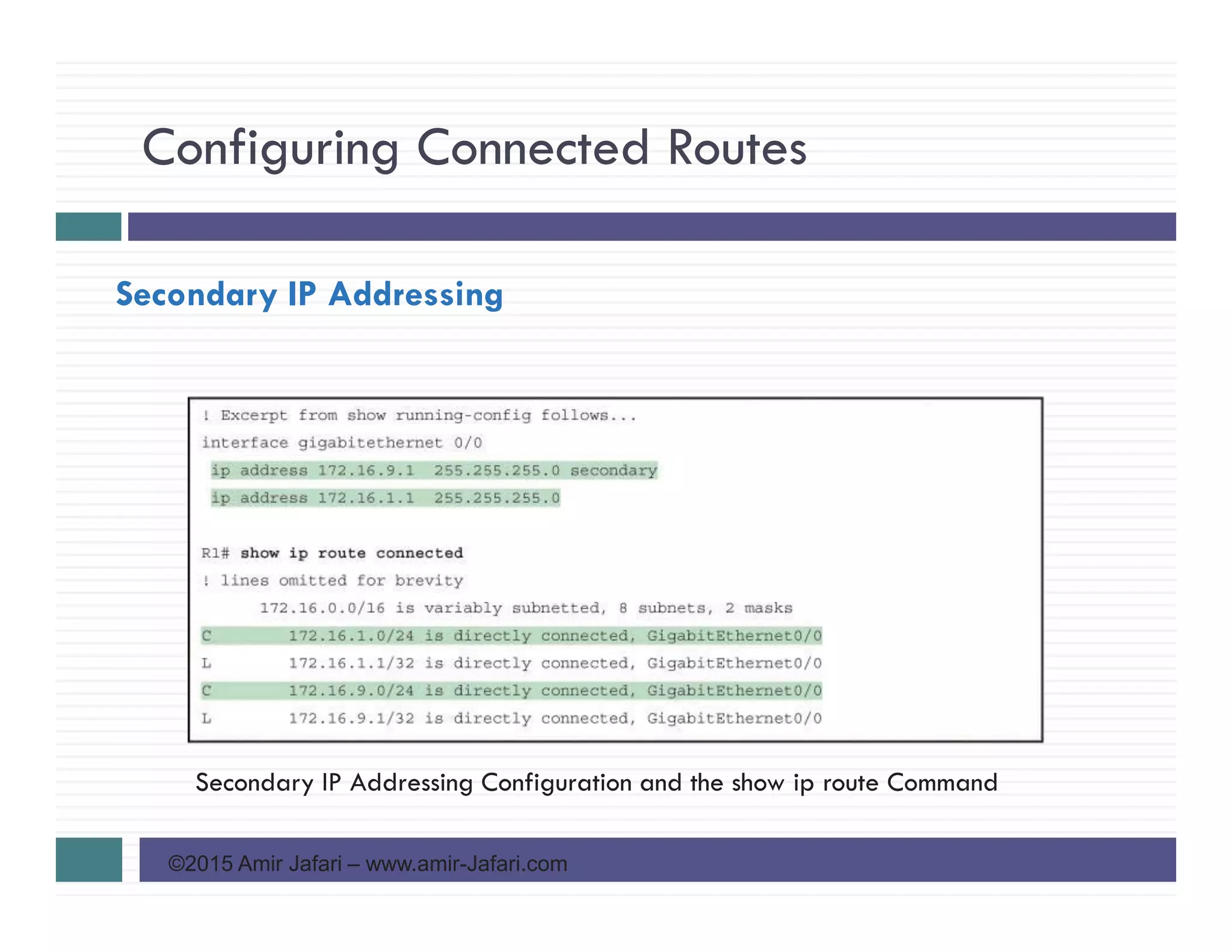
![Configuring Connected Routes
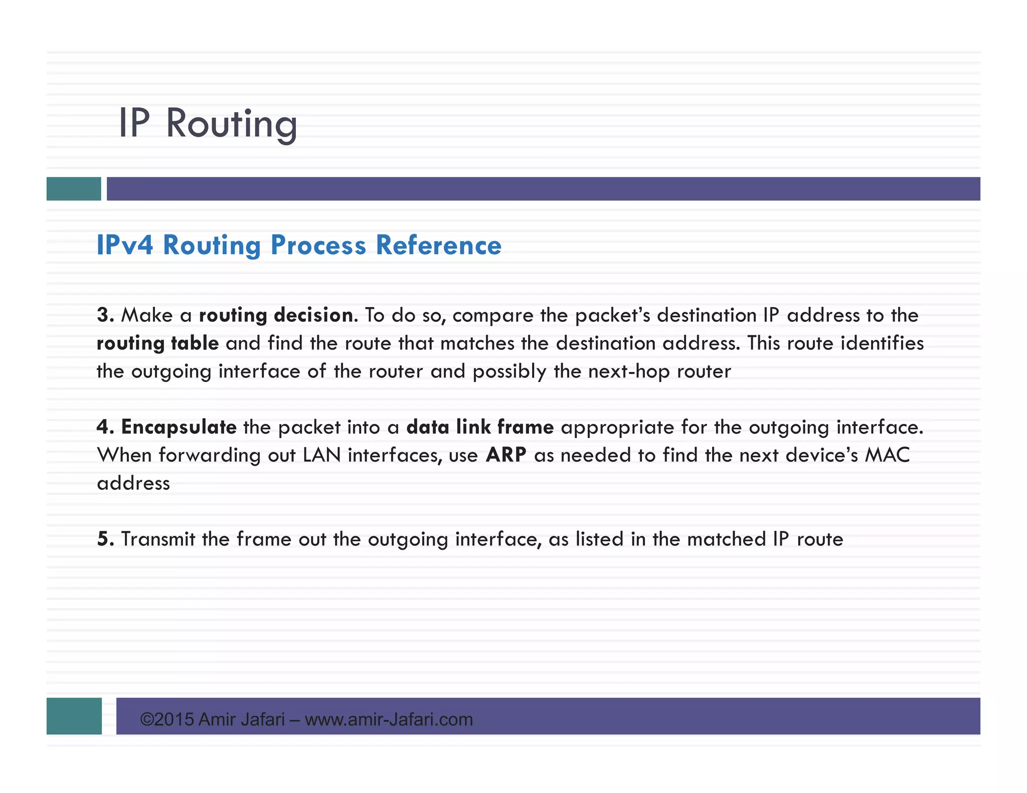
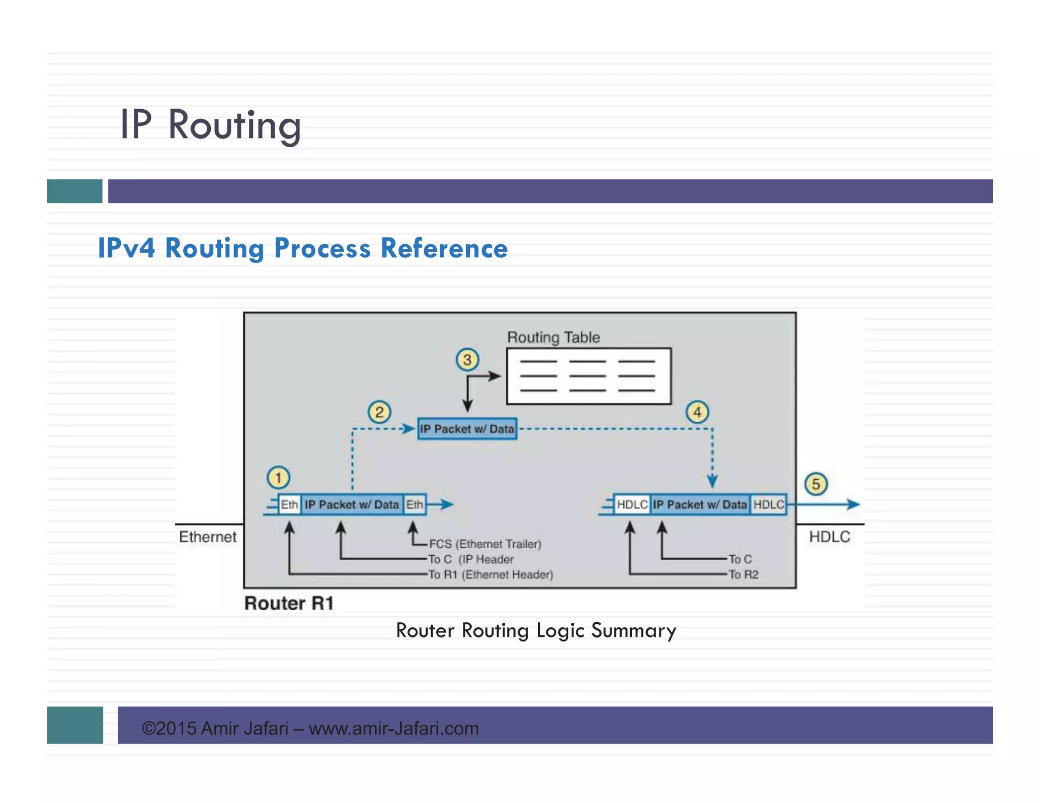
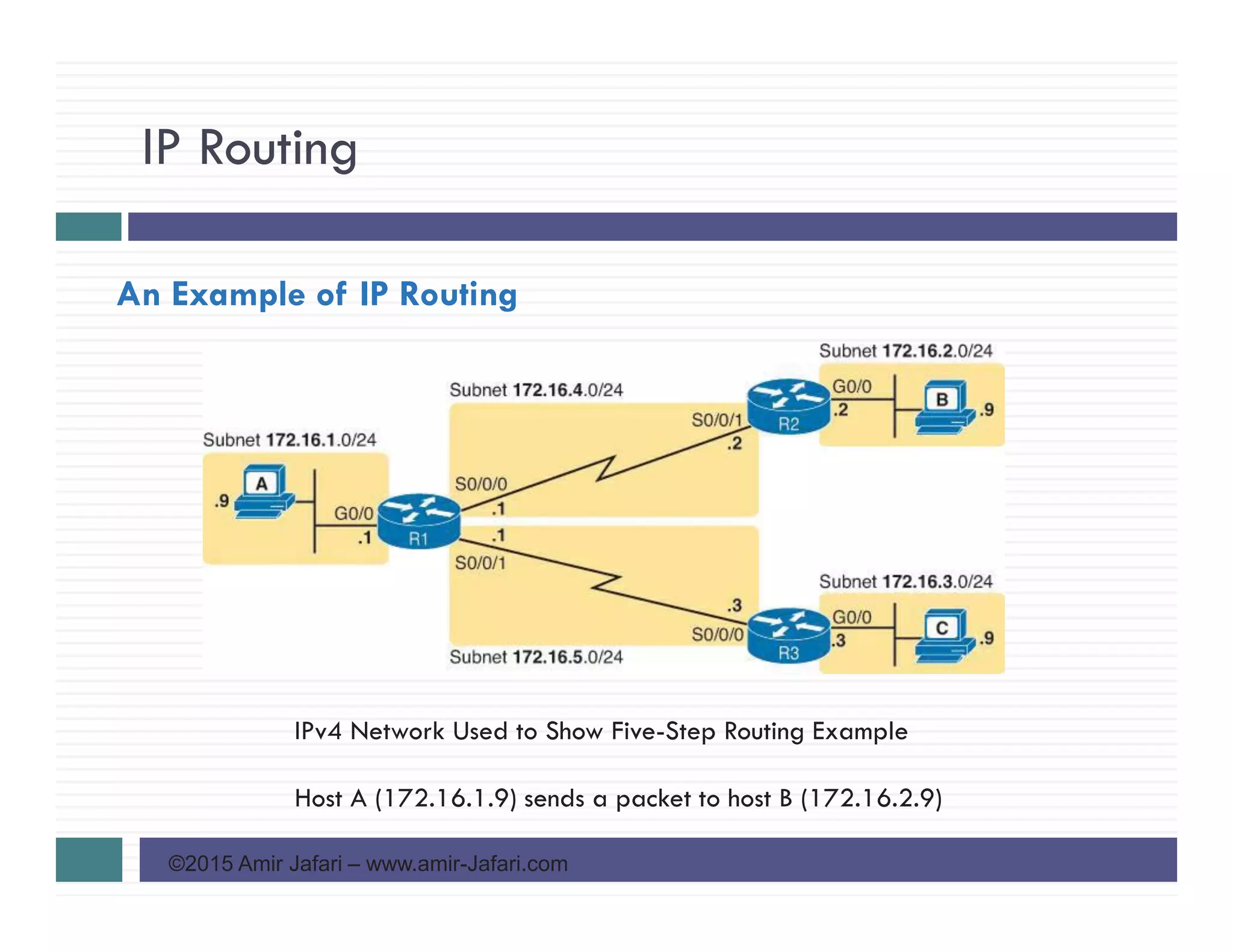
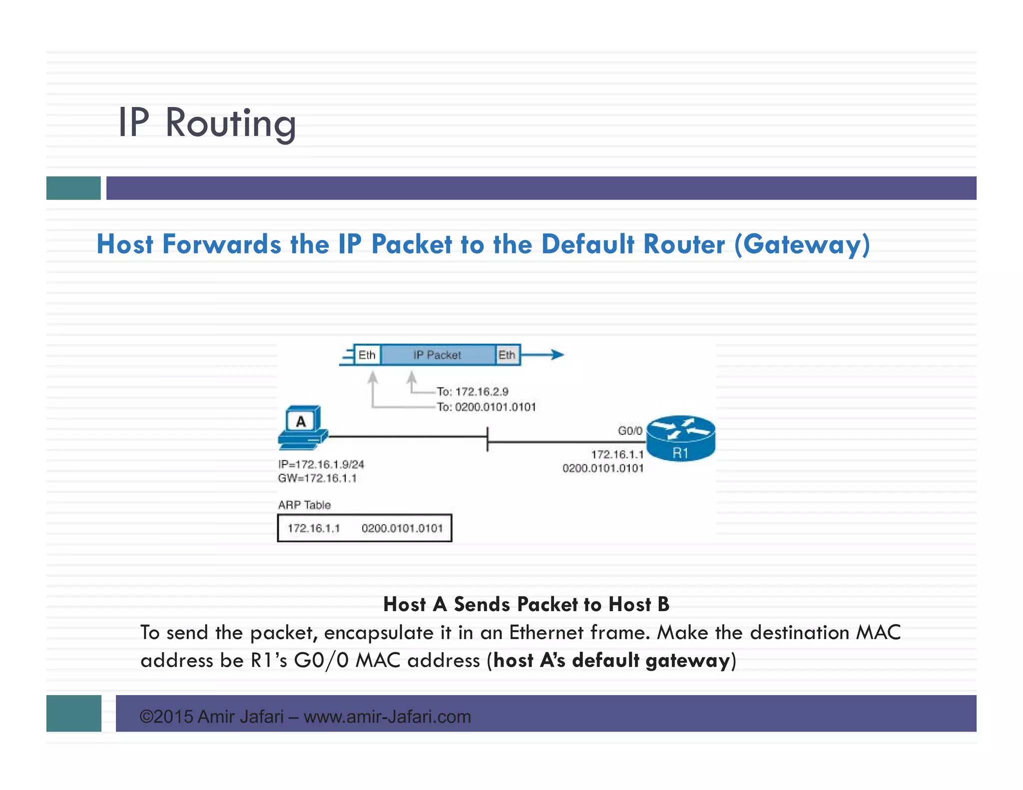
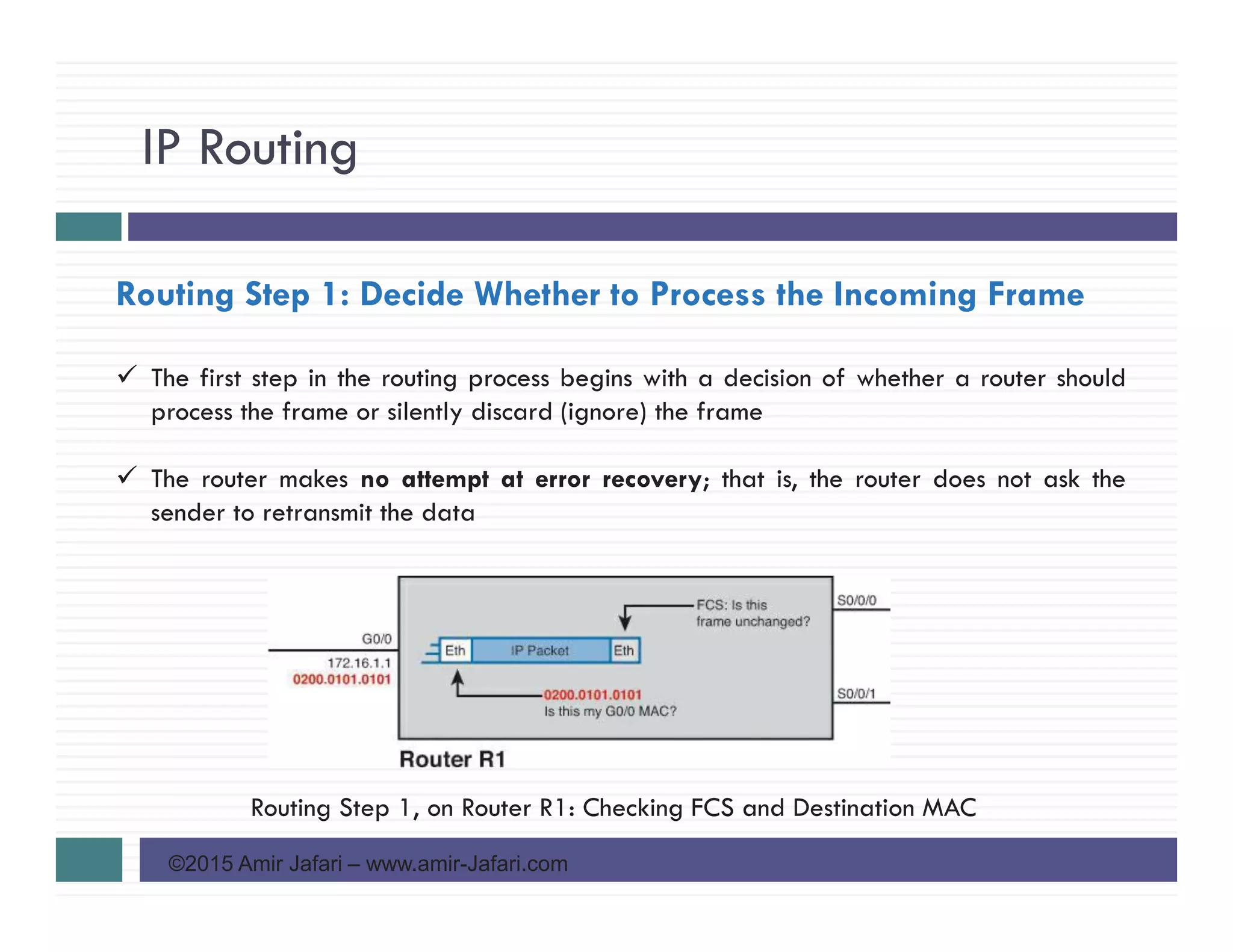
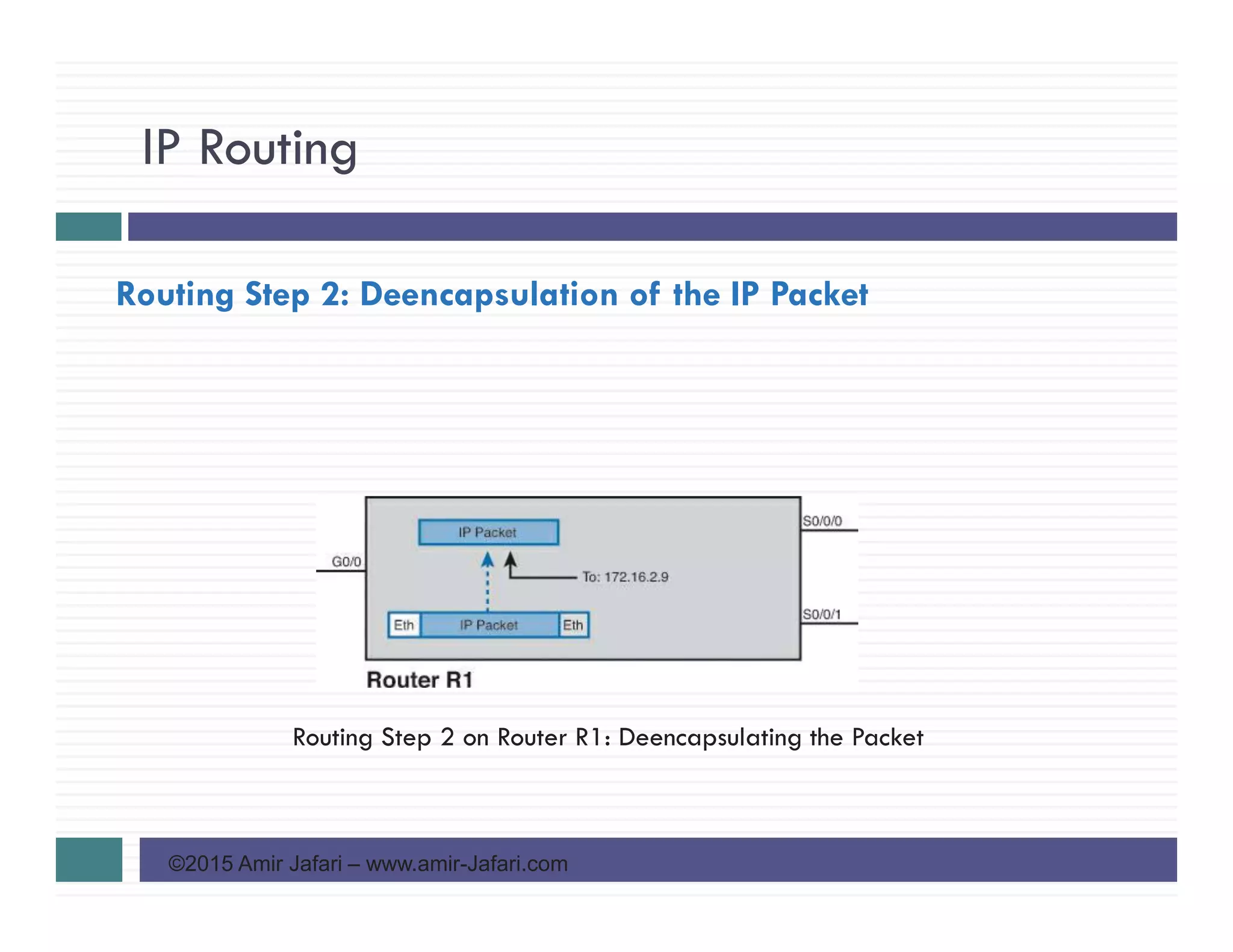
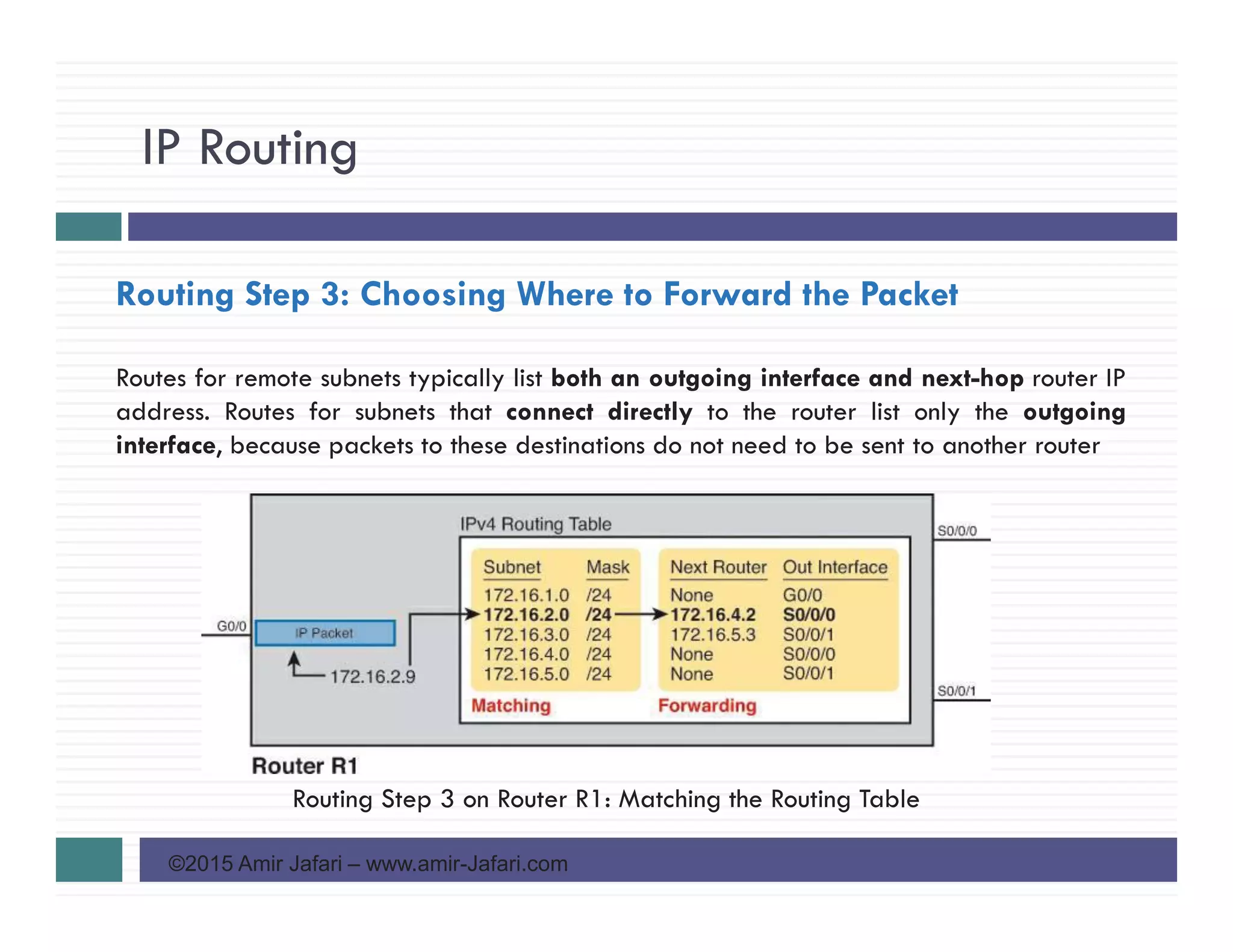
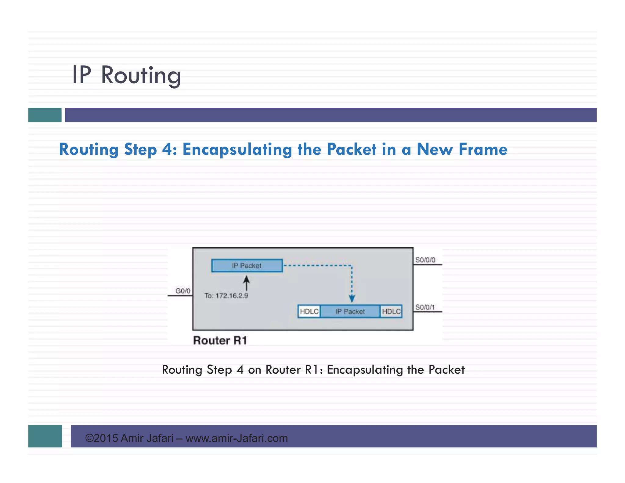
©2015 Amir Jafari – www.amir-Jafari.com
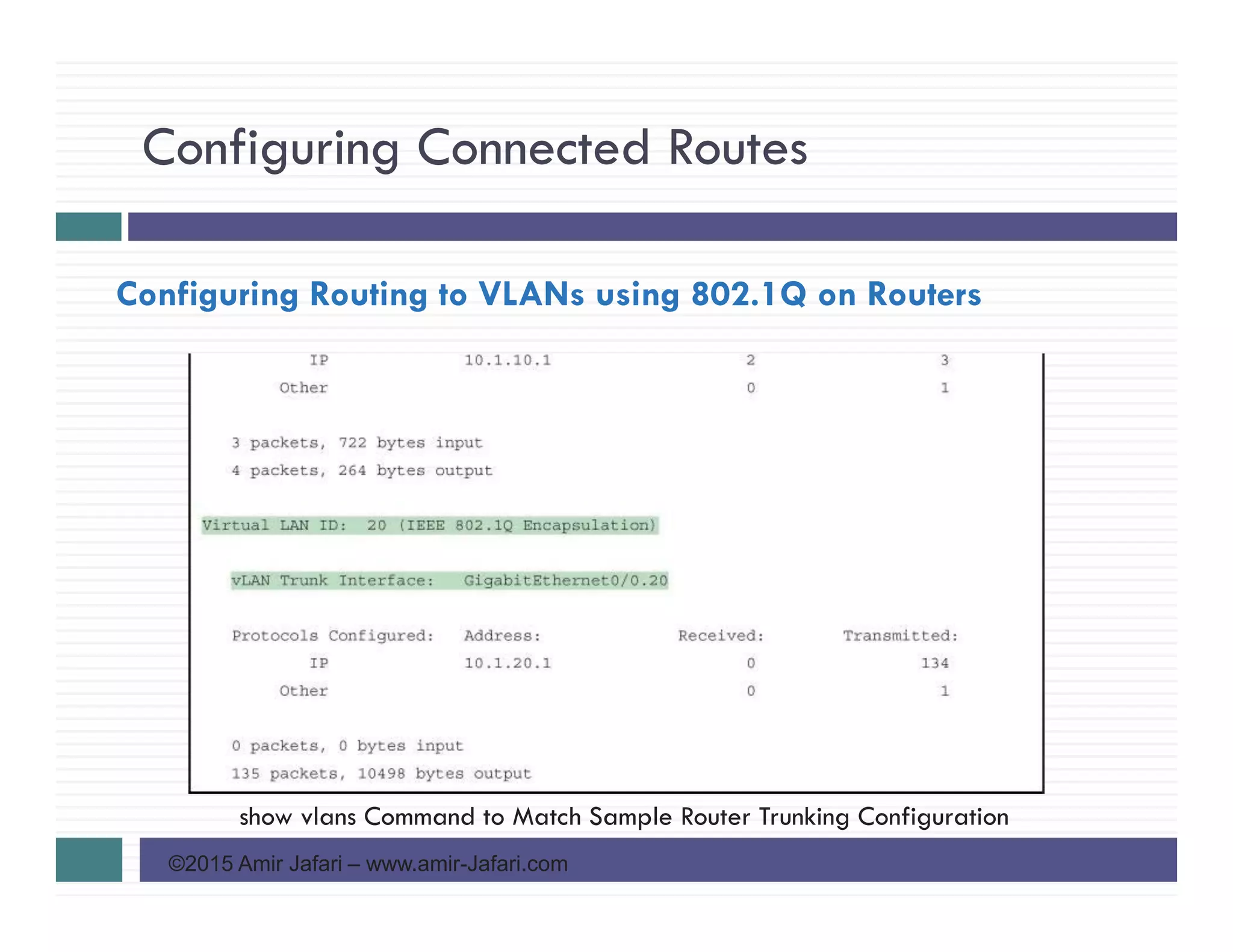
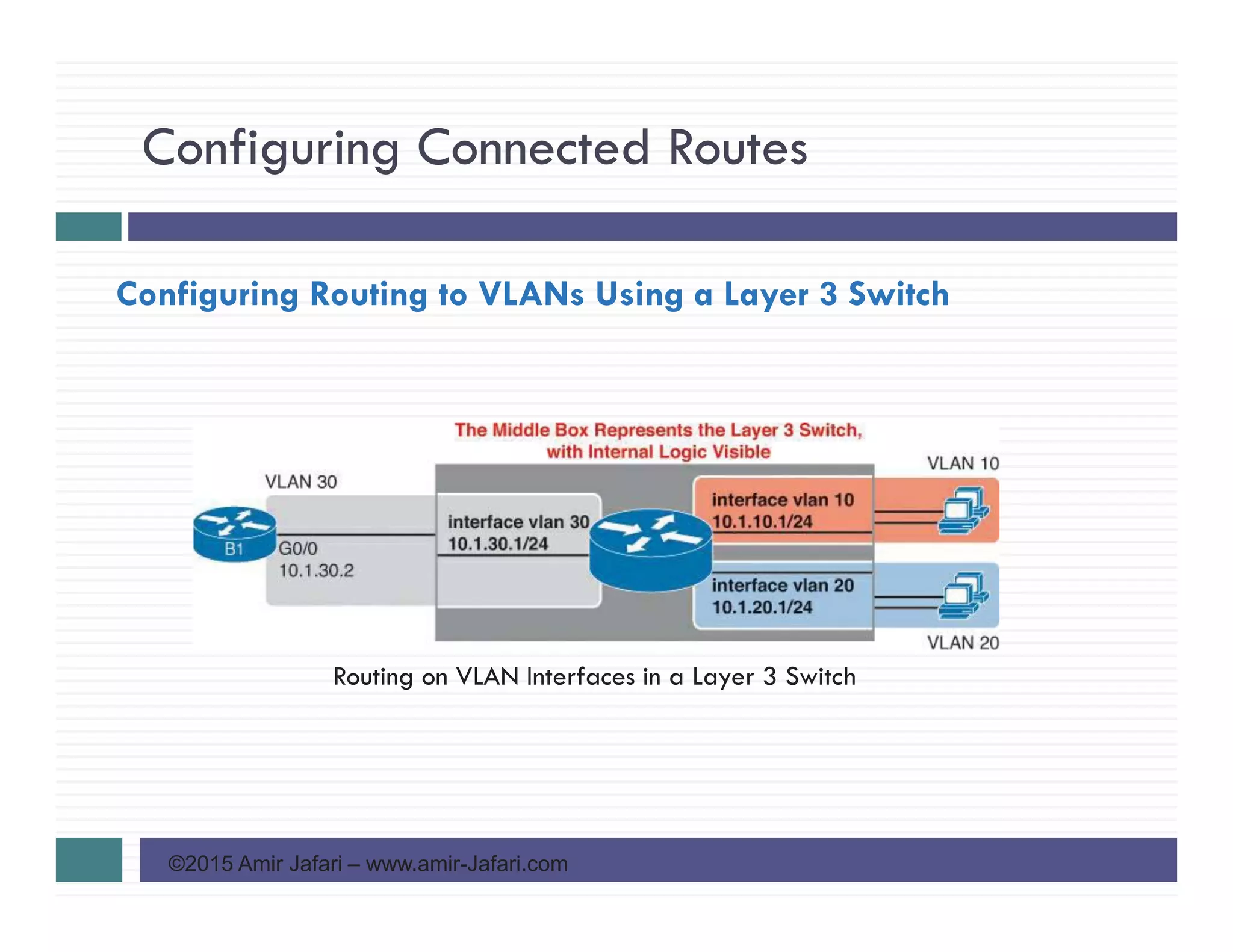
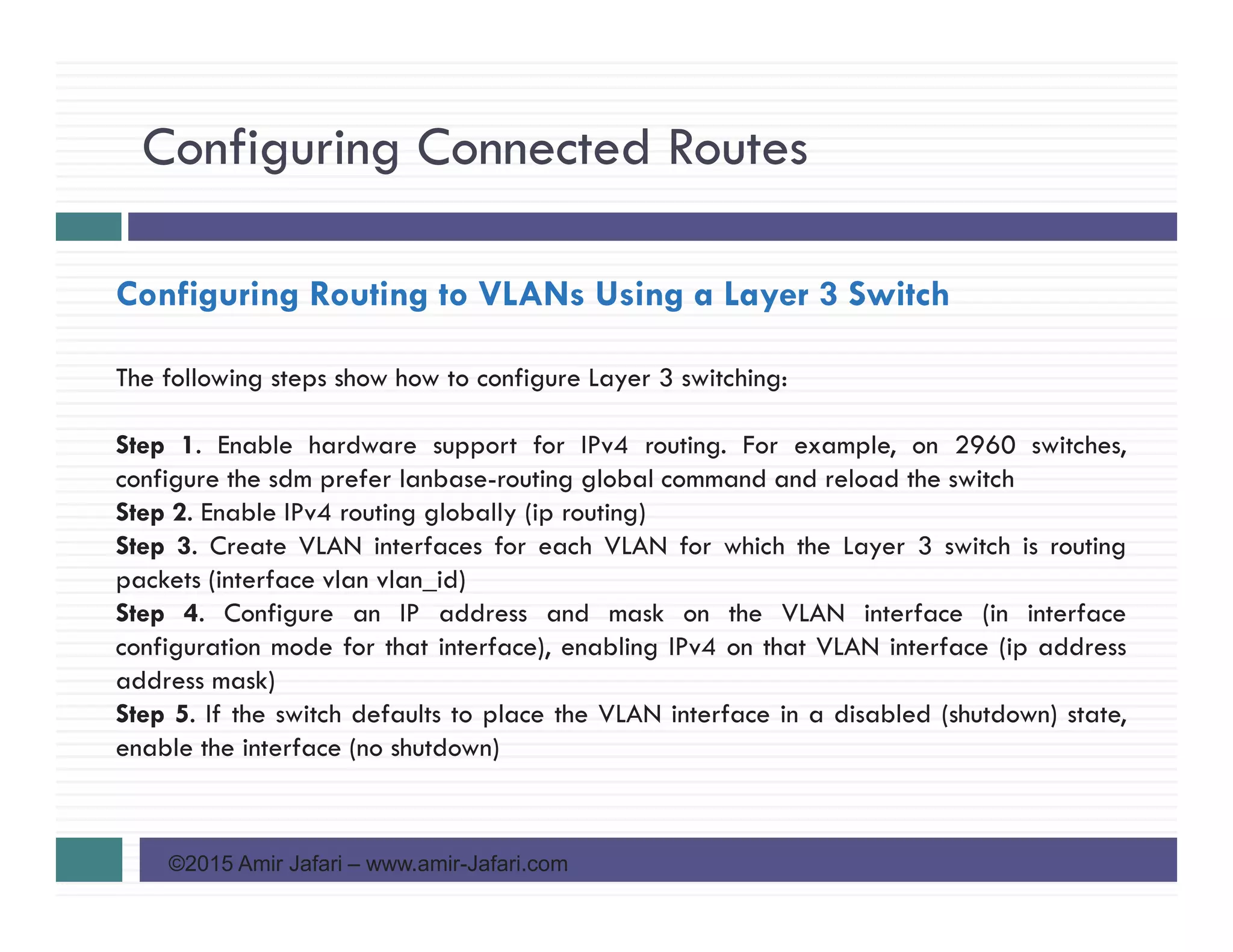
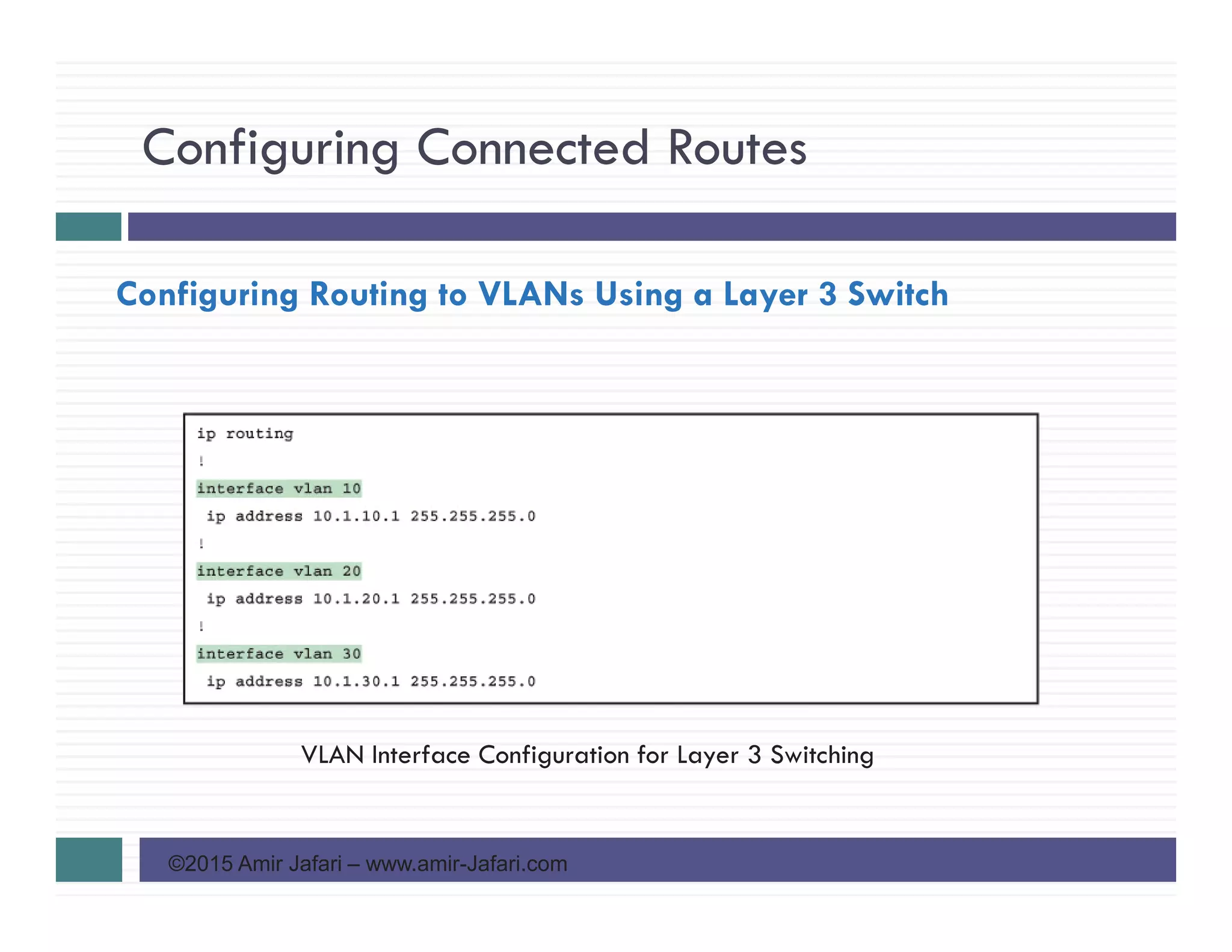
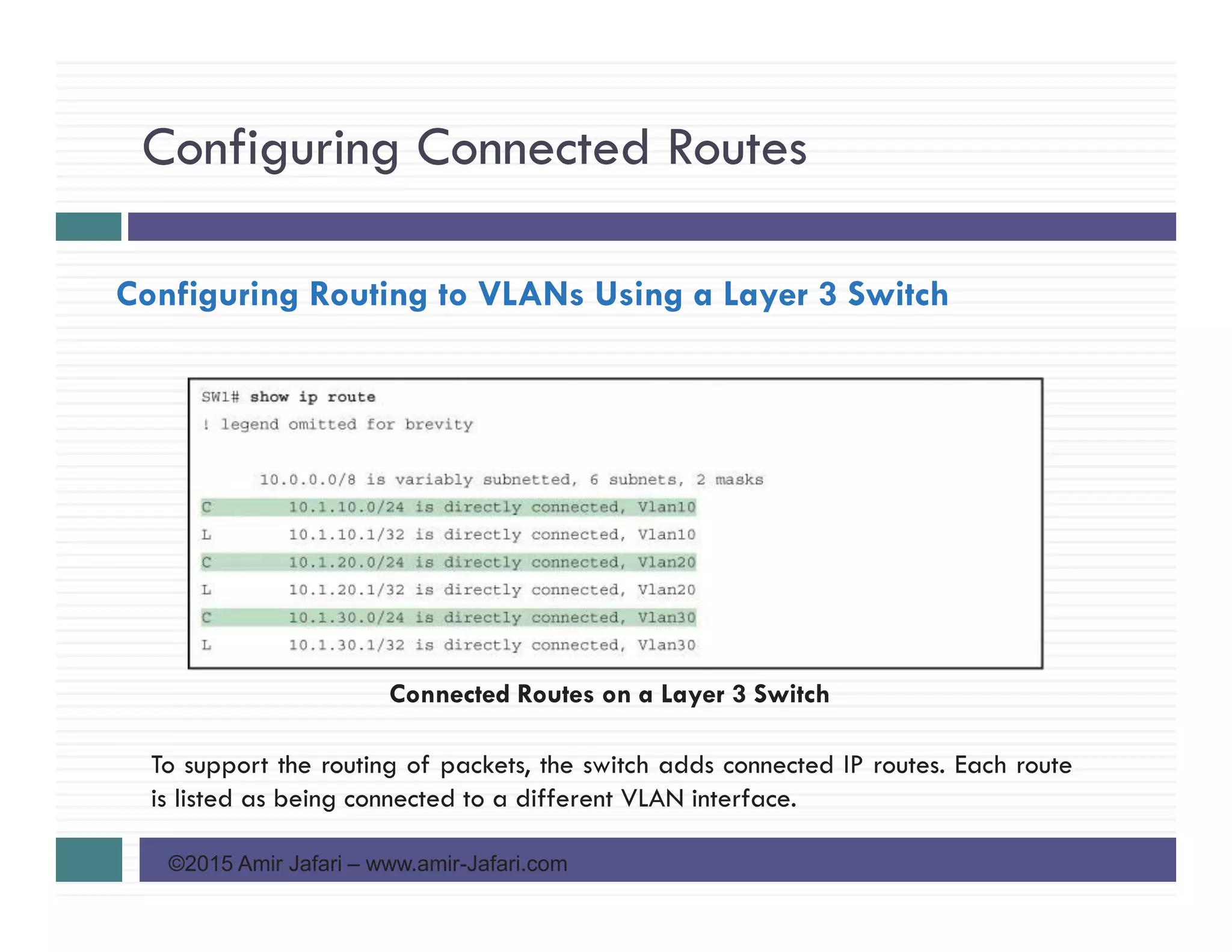
Configuring Routing to VLANs Using a Layer 3 Switch
A Layer 3 switch is one device that does two primary functions: Layer 2 LAN switching
and Layer 3 IP routing
The configuration of a Layer 3 switch mostly looks like the Layer 2 switching
configuration with a small bit of configuration added for the Layer 3 functions
The Layer 3 switching function needs a virtual interface connected to each VLAN
internal to the switch
These VLAN interfaces act like router interfaces, with an IP address and mask
The Layer 3 switch has an IP routing table, with connected routes off each of these
VLAN interfaces. (These interfaces are also referred to as Switched Virtual Interfaces
[SVI].)](https://image.slidesharecdn.com/ccnars-20-configuringipv4addressesandroutes-150928195244-lva1-app6891/75/CCNA-R-S-20-Configuring-IPv4-Addresses-and-Routes-42-2048.jpg)
![Configuring Connected Routes
©2015 Amir Jafari – www.amir-Jafari.com
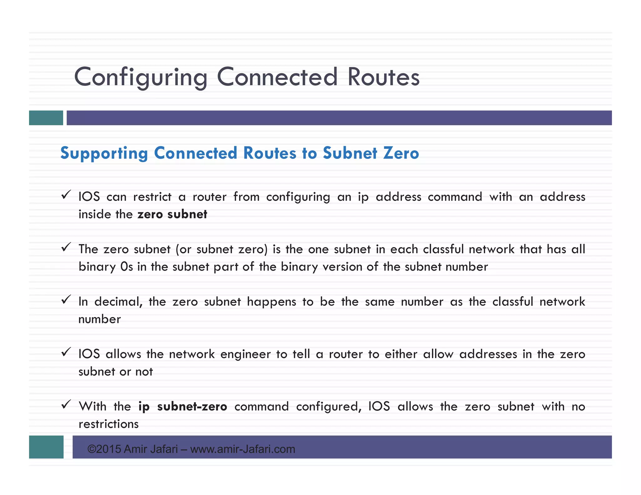
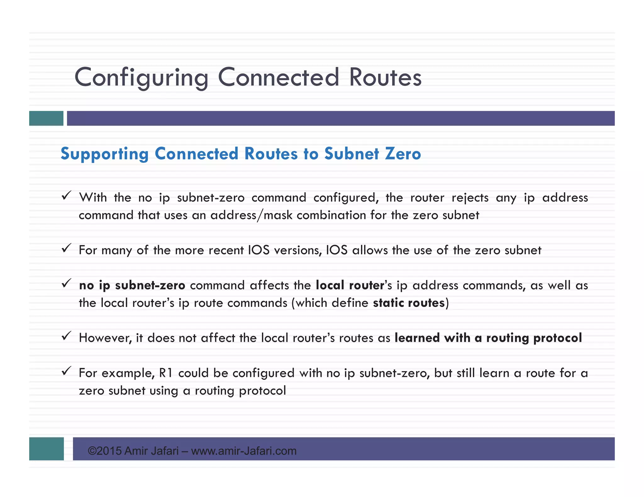
Supporting Connected Routes to Subnet Zero
Effects of [no] ip subnet-zero on a Local Router](https://image.slidesharecdn.com/ccnars-20-configuringipv4addressesandroutes-150928195244-lva1-app6891/75/CCNA-R-S-20-Configuring-IPv4-Addresses-and-Routes-53-2048.jpg)

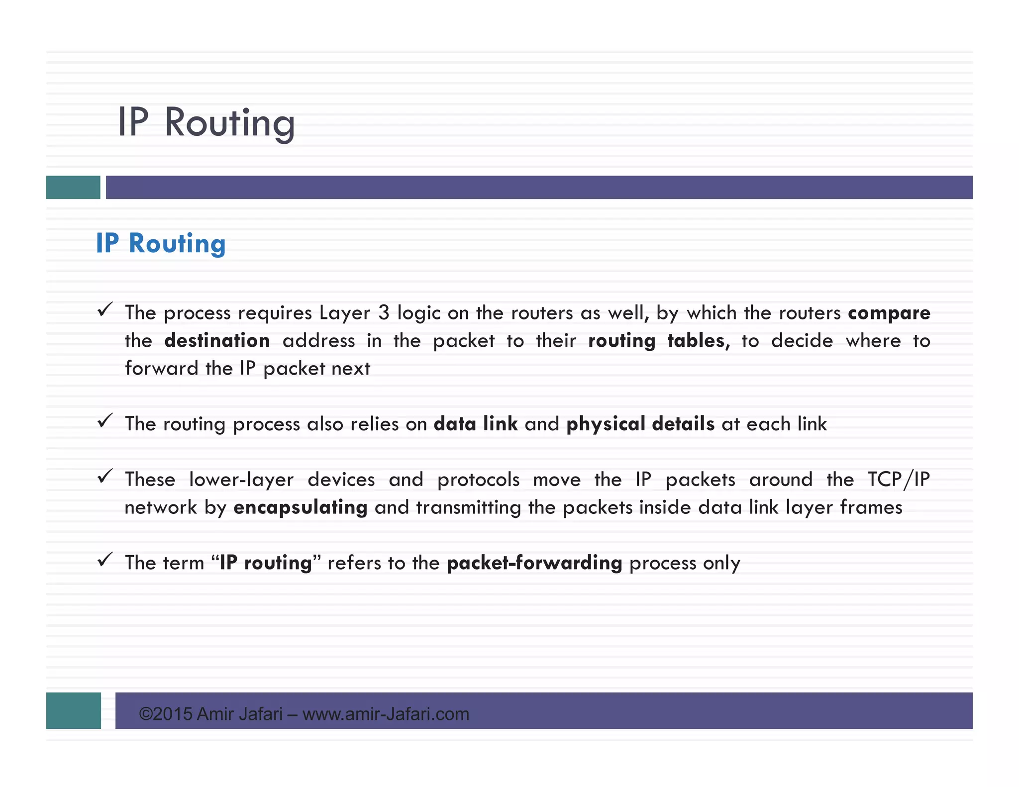
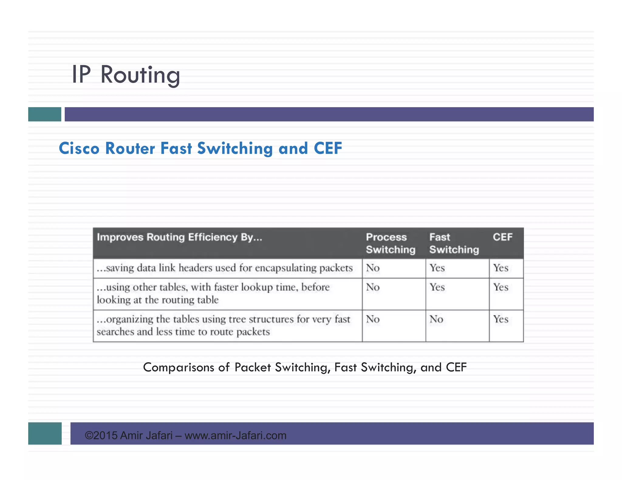
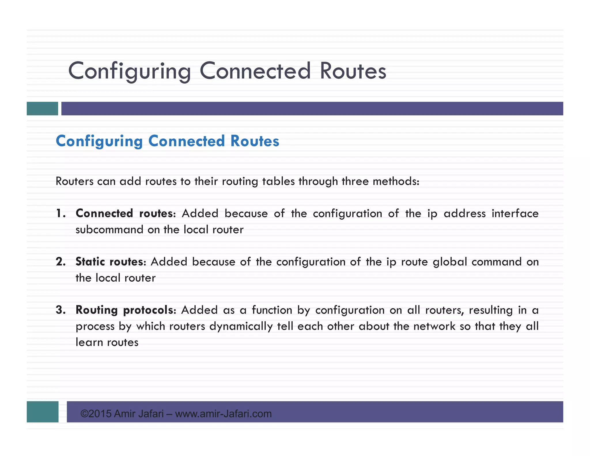
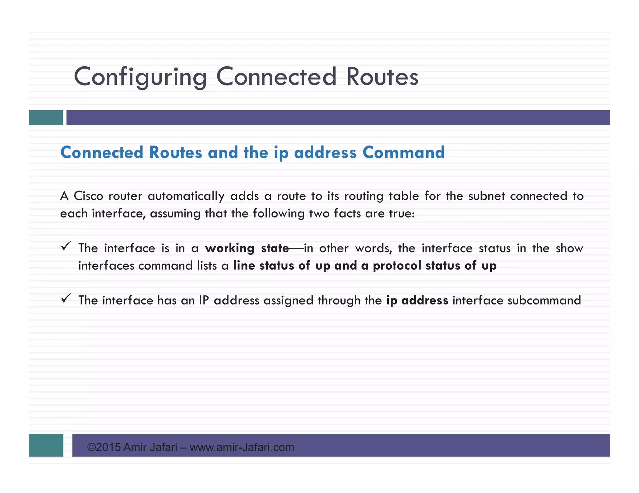
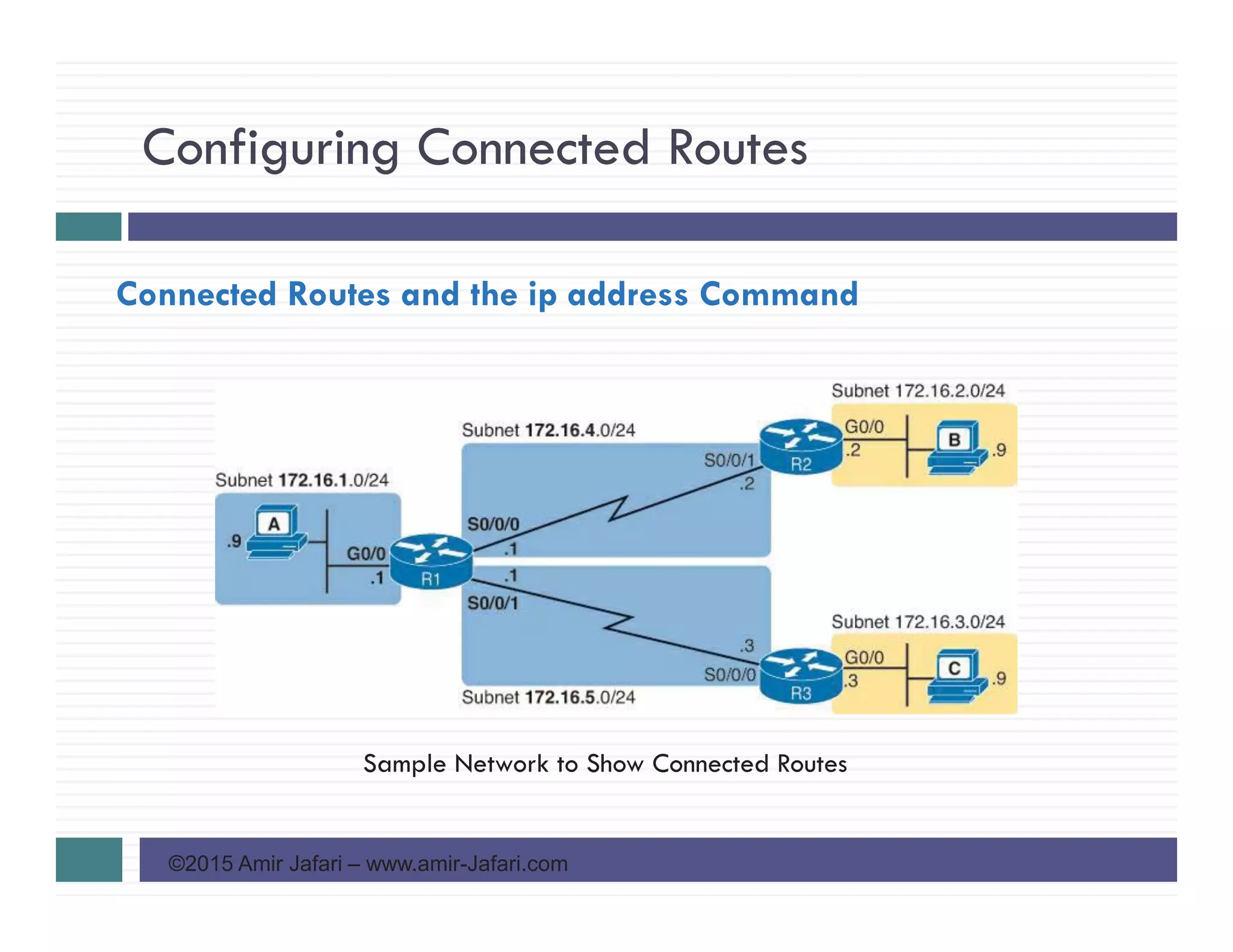
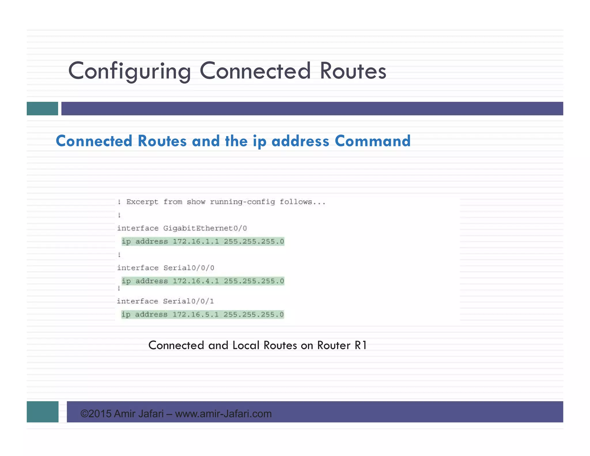
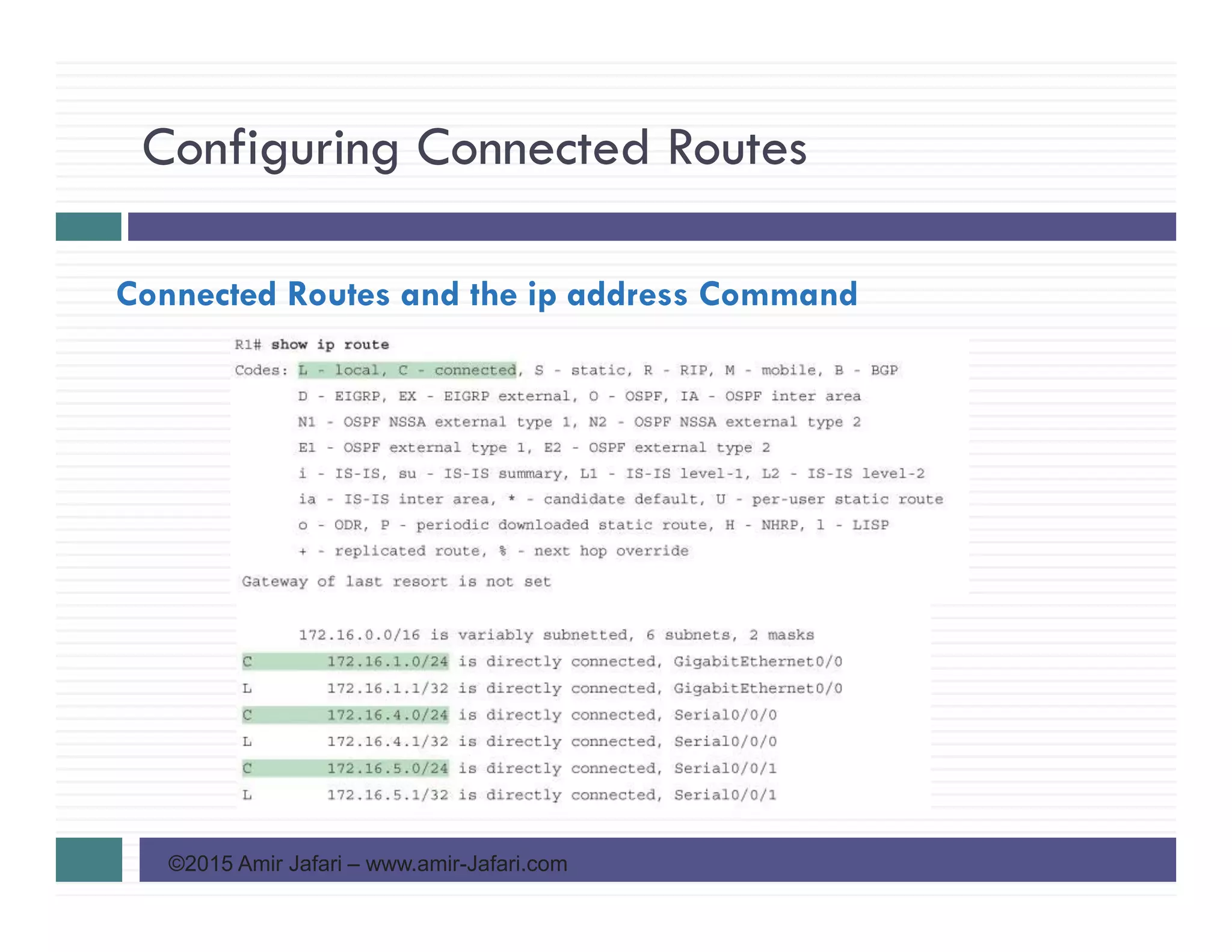
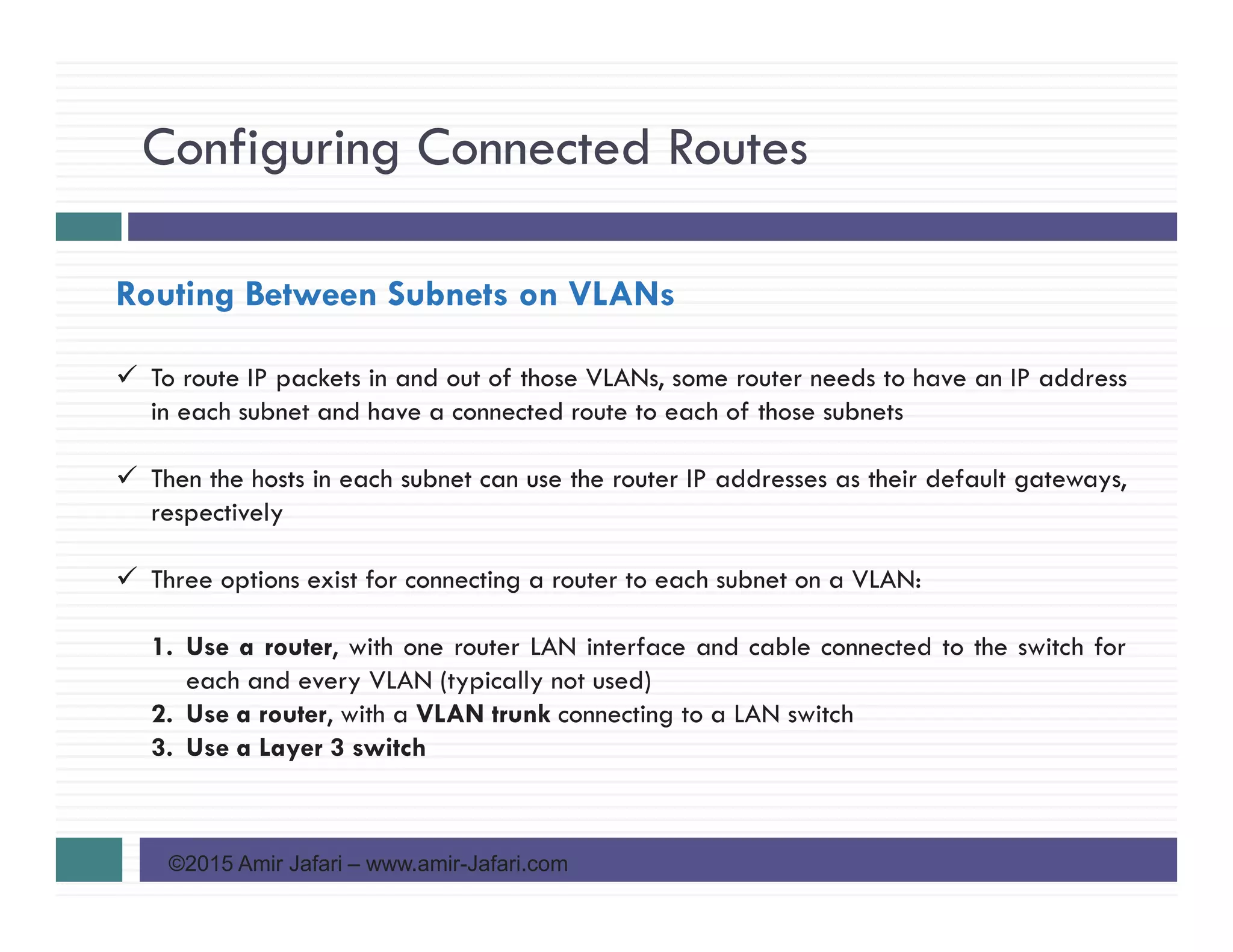
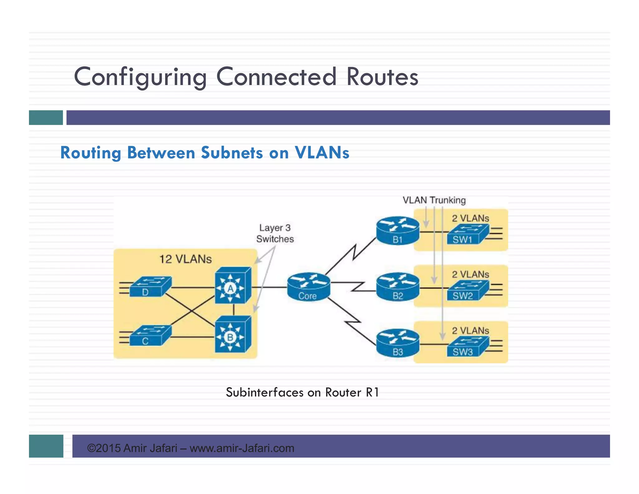
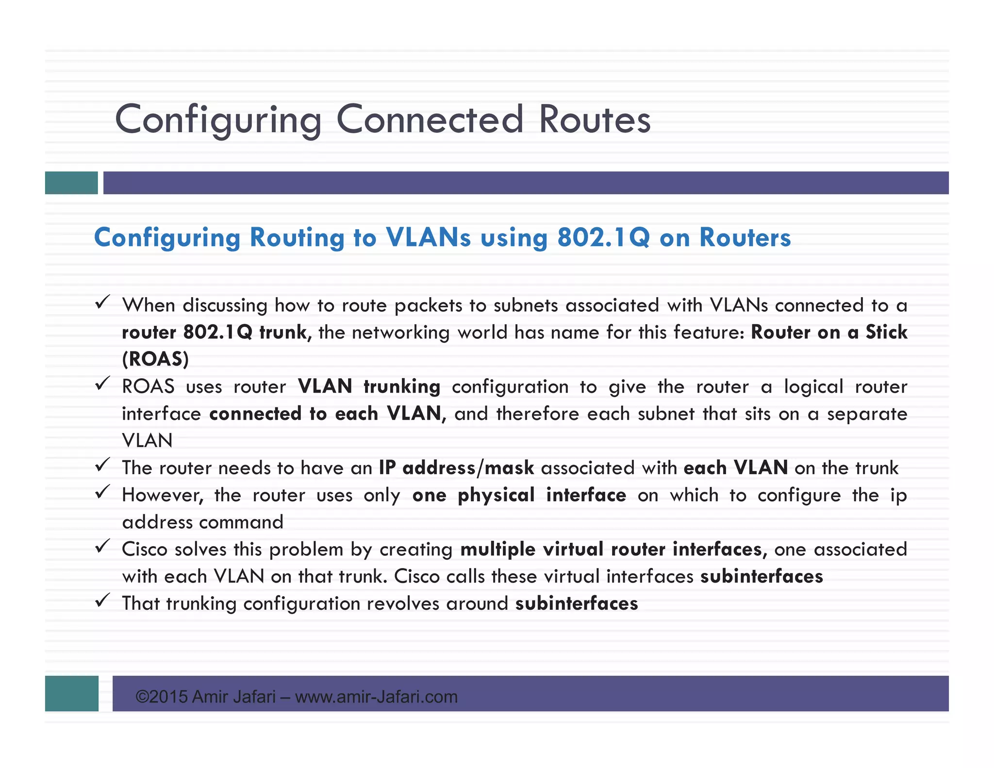
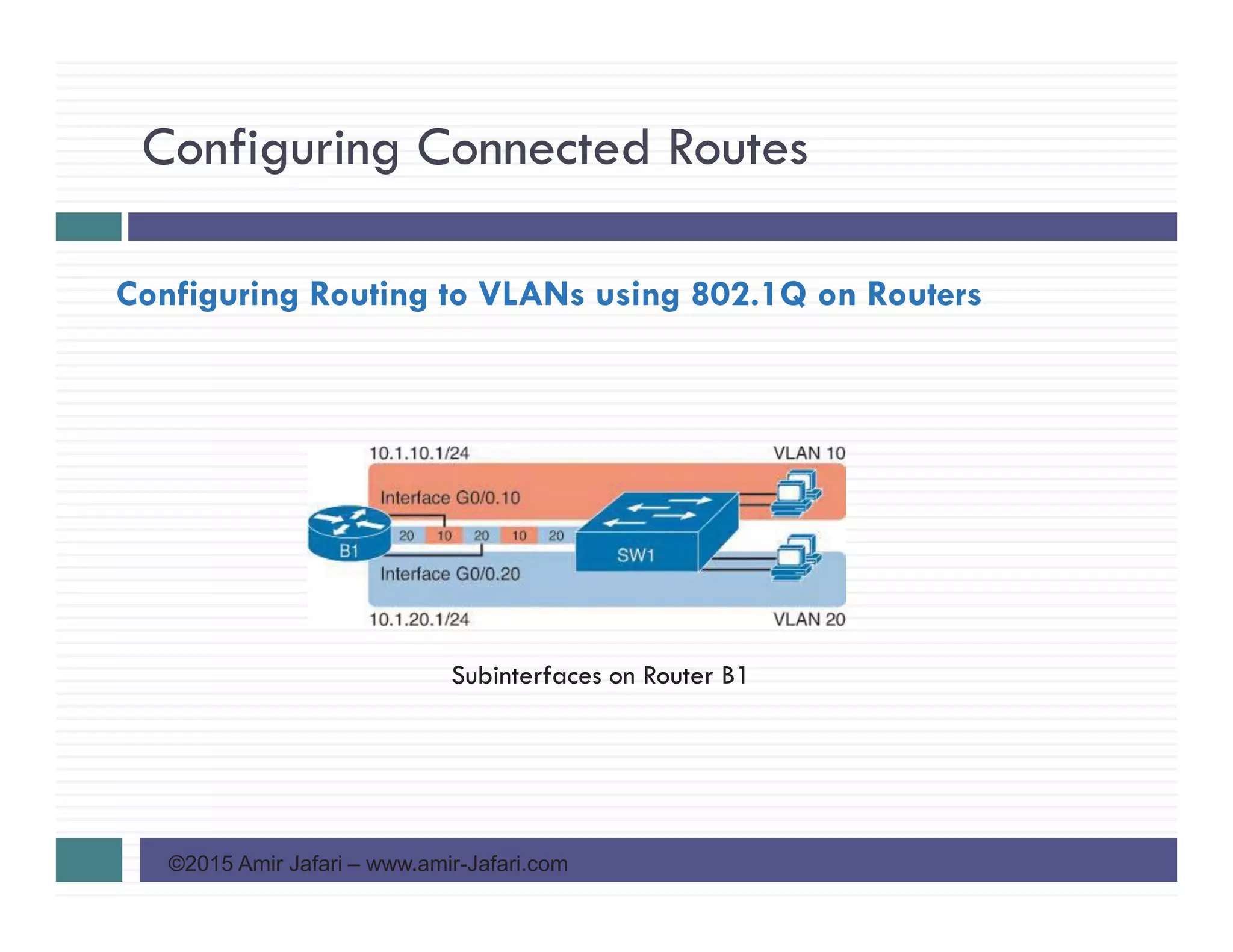
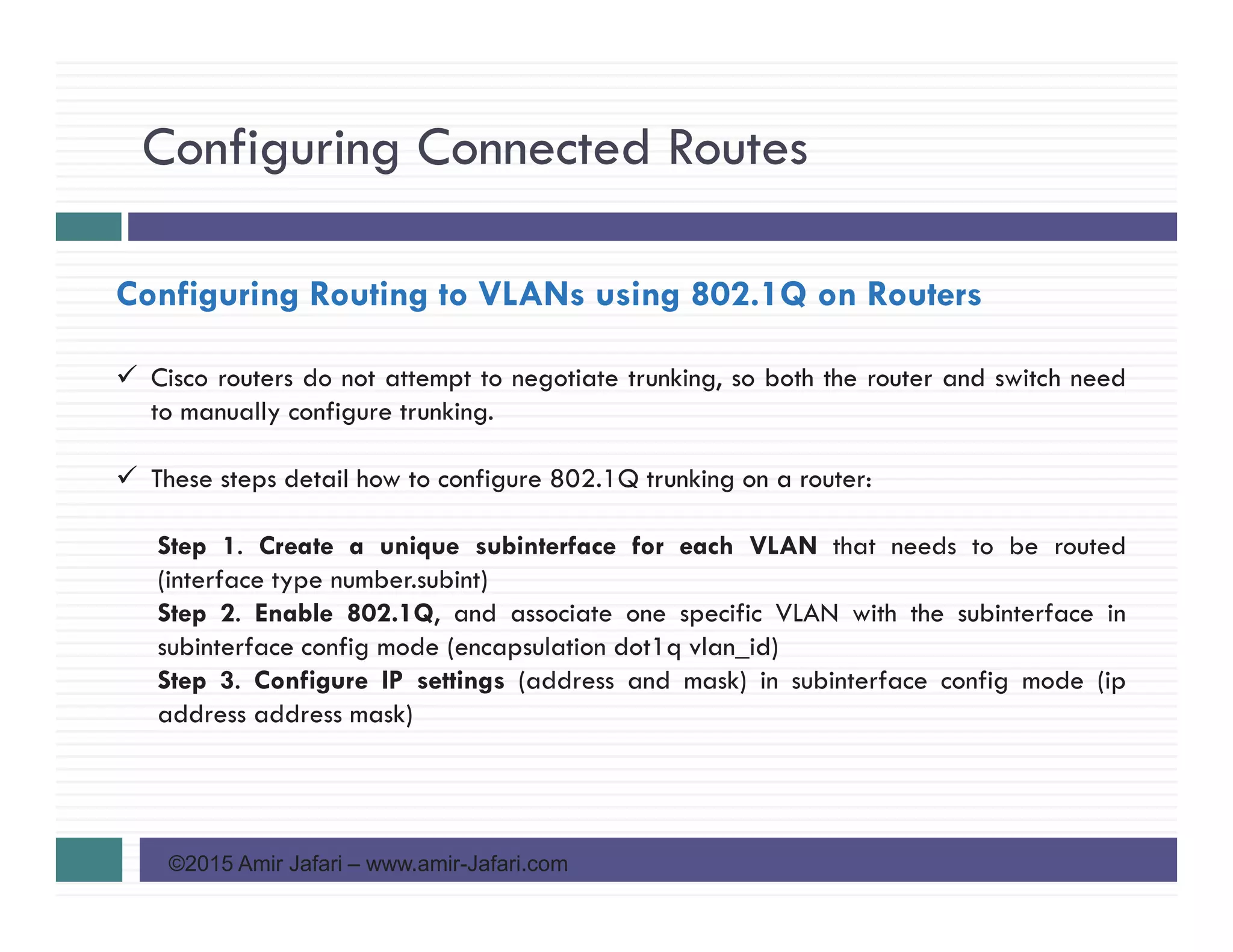
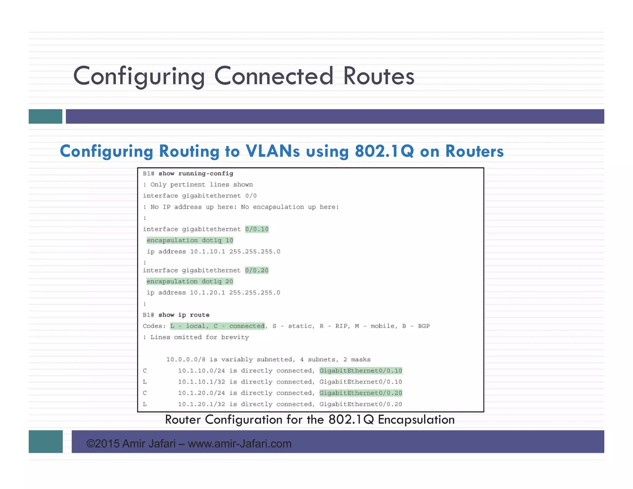
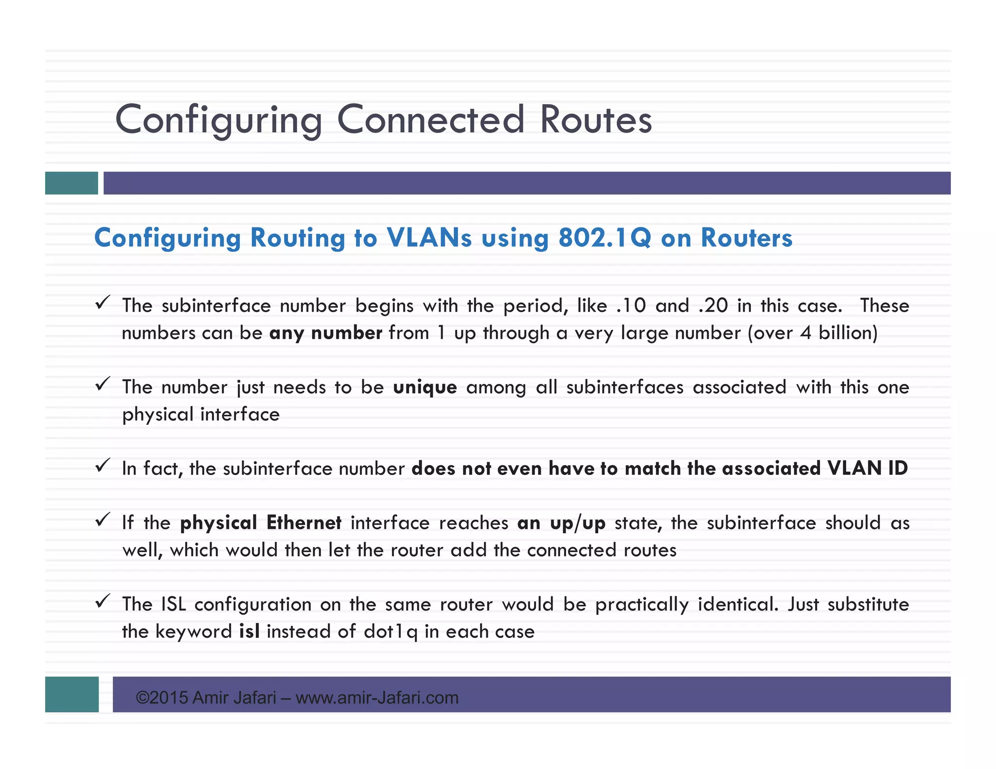
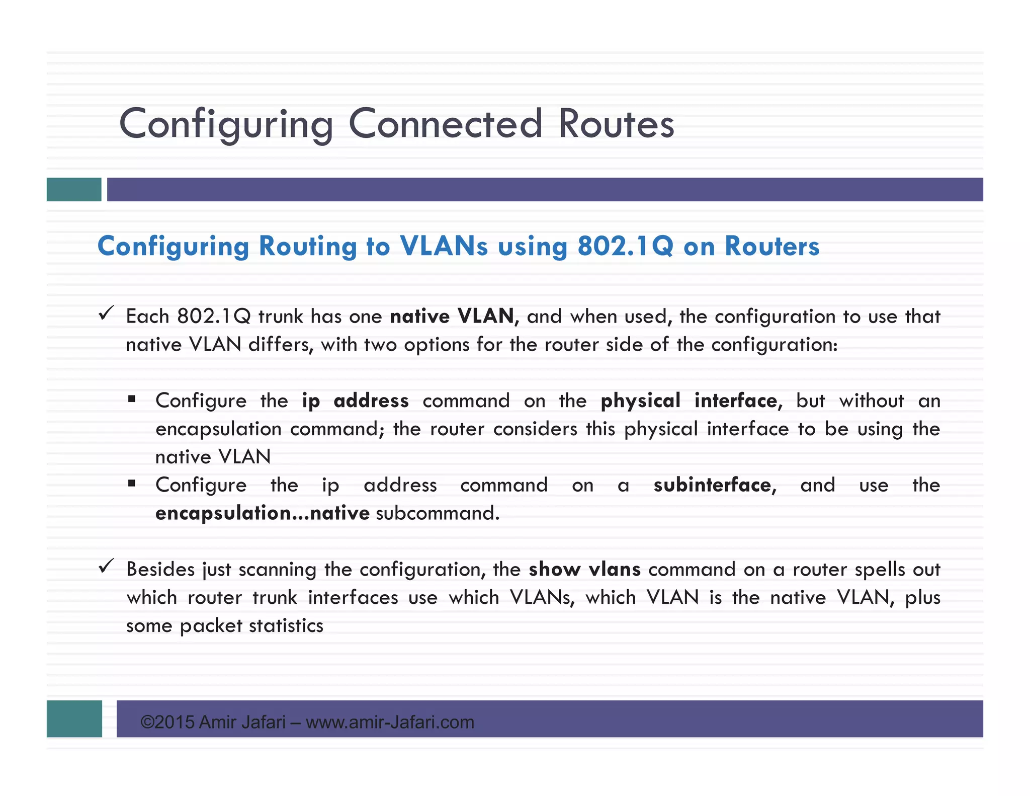
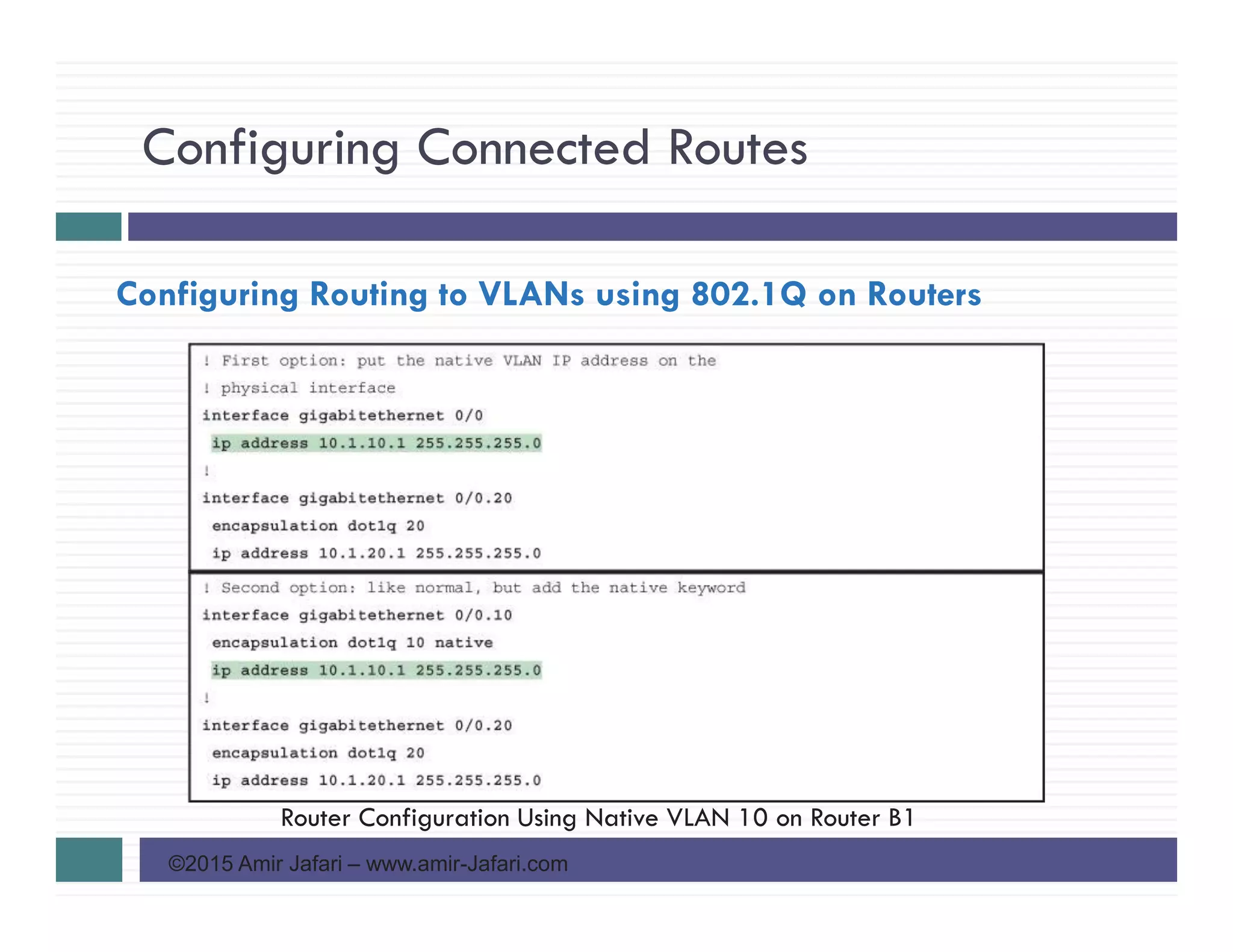
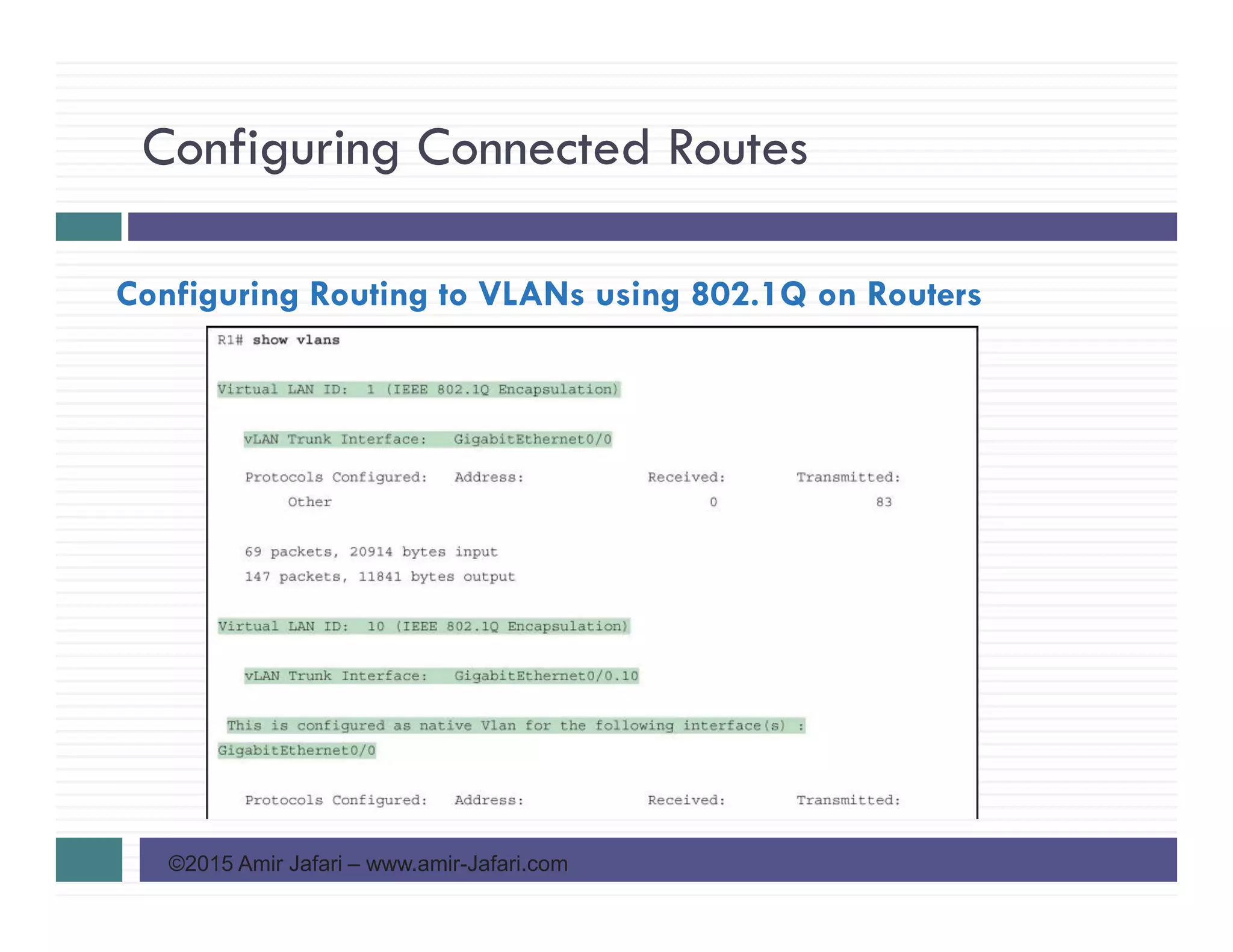
This document discusses configuring IPv4 addresses and routes on routers. It covers: - Connected routes are automatically added for subnets connected to router interfaces when the interface has an IP address configured. - Routers can route between VLAN subnets using subinterfaces on a physical interface connected via an 802.1Q trunk. Each subinterface represents a VLAN and requires an IP address for the associated subnet. - Configuring IP addresses on subinterfaces and enabling 802.1Q trunking with the correct VLAN ID allows a router to route between VLAN subnets using only one physical interface.


![Chapter [27/11, 11:00 am] Sumaya👸🏻✨️: Mida kale waqtiga wuba kudhamaadaye [28...](https://cdn.slidesharecdn.com/ss_thumbnails/chapter2-staticrouting-241202055828-36f50cbd-thumbnail.jpg?width=640&height=640&fit=bounds)


![Coded Agents – with UiPath SDK + LangGraph [Virtual Hands-on Workshop]](https://cdn.slidesharecdn.com/ss_thumbnails/codedagentsdeck-251215155422-5497c599-thumbnail.jpg?width=640&height=640&fit=bounds)


