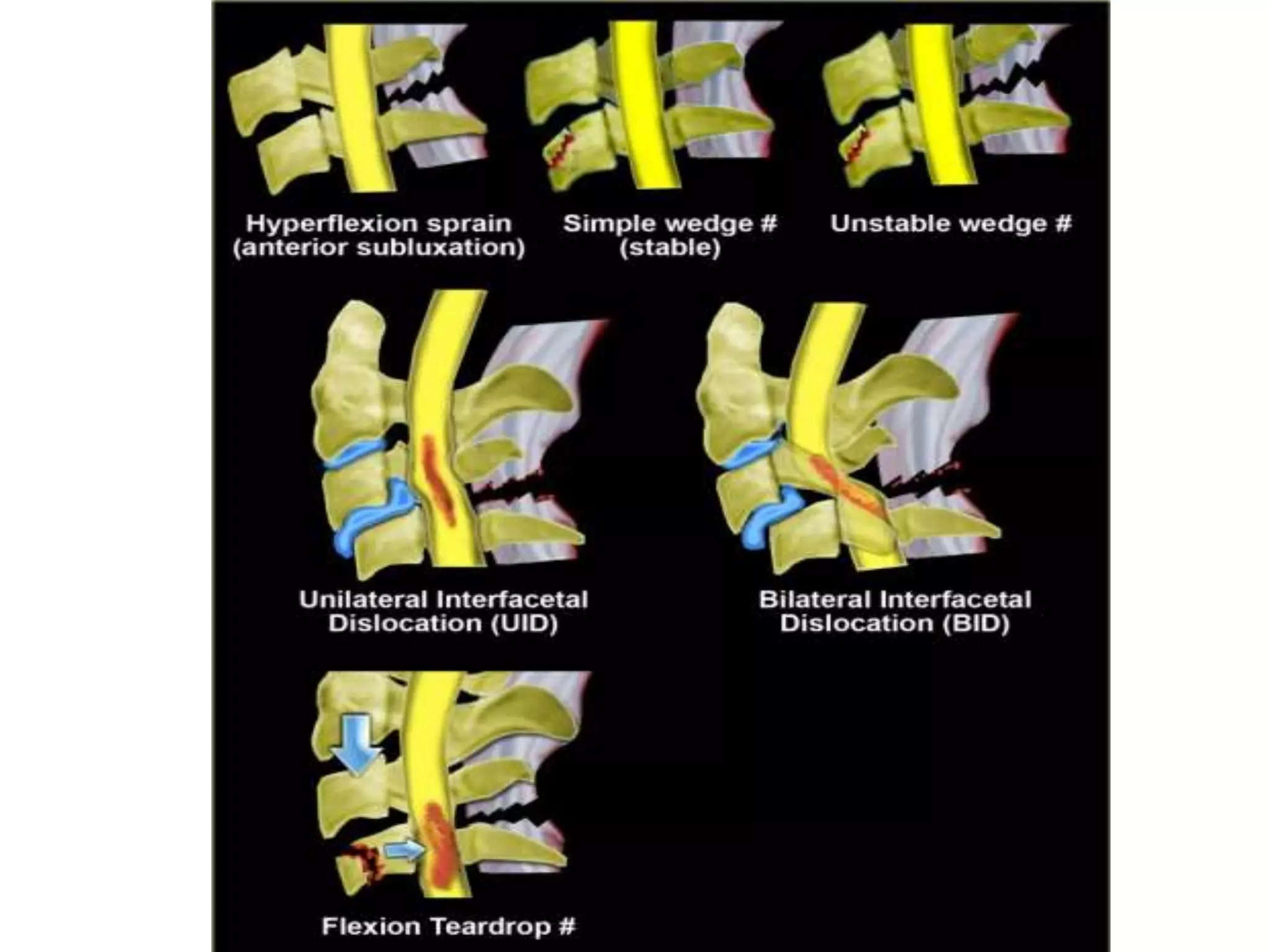
The document discusses various types of cervical spine trauma and injuries that can occur. It describes fractures of the atlas including Jefferson's fracture and posterior arch fractures. Hangman's fractures and teardrop fractures of the axis are also summarized. Odontoid fractures are divided into Types I-III. Vertebral body compression fractures like wedge fractures and burst fractures are mentioned. The document also briefly summarizes clay shoveler's fractures and lamina and transverse process fractures of the cervical spine. Various imaging modalities for evaluating cervical spine injuries are also discussed.
Cervical spine clearance lecture given to 1st-year emergency medicine residents at Duke University. Covers indications for applying cervical collar, types of collars, types of imaging of the spine, and when to remove the collar.
Dr. Donald Corenman (http://neckandback.com 970.479.5895) is a spine surgeon and spinal cord expert practicing at the Steadman Clinic in Vail, CO. He created this Power Point presentation on cervical spine injury and the evaluation of the cervical spine with an injury. The cervical spine (C spine) represents the neck area of the upper spine.
This presentation--clearing the cervical spine--offers an in-depth look at cervical spine injury of the neck (C spine) including fractures, cervical nonskeletal injuries, and also offers a 3-view radiograph approach into the exam.
Dr. Corenman is a spine expert and treats nonskeletal injuries such as ligamentous instability, sciwora and central cord injury. He is an expert in myelopathy, sciatica, degenerative disc disease, scoliosis and slipped disc.
1) Subtrochanteric Fracture
Subtrochanteric typically defined as area from lesser trochanter to 5cm distal fractures with an associated intertrochanteric component may be called peritrochanteric fracture.
*Unique Aspect
Blood loss is greater than with femoral neck or trochanteric fractures – covered with anastomosing branches of the medial and lateral circumflex femoral arteries branch of profunda femoris trunk.
2) Femoral Shaft Fracture
Femoral shaft fracture is defined as a fracture of the diaphysis occurring between 5 cm distal to the lesser trochanter and 5 cm proximal to the adductor tubercle
The femoral shaft is padded with large muscles.
- reduction can be difficult as muscle contraction displaces the fracture
- healing potential is improved by having this well-vascularized
*Age
-usually a fracture of young adults and results from a high energy injury
-elderly patients should be considered ‘pathological’ until proved otherwise
-children under 4 years the suspected possibility of physical abuse
*FRACTURES ASSOCIATED WITH VASCULAR INJURY
Warning signs of an associated vascular injury are
(1) excessive bleeding or haematoma formation; and
(2) paraesthesia, pallor or pulselessness in the leg and foot.
~Warm ischemia in 2-3H
~If > 6H – salvage not possible
*‘FLOATING KNEE’
Ipsilateral fractures of the femur and tibia may leave the knee joint ‘floating’
3) Distal Femoral Fracture
Defined as fractures from articular surface to 5cm above metaphyseal flare
*clinical feature
The knee is swollen because of a haemarthrosis – this can be severe enough to cause blistering later
Movement is too painful to be attempted
The tibial pulses should always be checked to ensure the popliteal artery was not injured in the fracture.
Reference: Apley's System of Orthopaedic and Fracture (9th edition)
In this presentation we will discuss the basic of axial trauma from head to pelvis. We will discuss the important key points that aids in the diagnosis of axial trauma
The French Revolution, which began in 1789, was a period of radical social and political upheaval in France. It marked the decline of absolute monarchies, the rise of secular and democratic republics, and the eventual rise of Napoleon Bonaparte. This revolutionary period is crucial in understanding the transition from feudalism to modernity in Europe.
For more information, visit-www.vavaclasses.com
How to Make a Field invisible in Odoo 17Celine George
It is possible to hide or invisible some fields in odoo. Commonly using “invisible” attribute in the field definition to invisible the fields. This slide will show how to make a field invisible in odoo 17.
Palestine last event orientationfvgnh .pptxRaedMohamed3
An EFL lesson about the current events in Palestine. It is intended to be for intermediate students who wish to increase their listening skills through a short lesson in power point.
This is a presentation by Dada Robert in a Your Skill Boost masterclass organised by the Excellence Foundation for South Sudan (EFSS) on Saturday, the 25th and Sunday, the 26th of May 2024.
He discussed the concept of quality improvement, emphasizing its applicability to various aspects of life, including personal, project, and program improvements. He defined quality as doing the right thing at the right time in the right way to achieve the best possible results and discussed the concept of the "gap" between what we know and what we do, and how this gap represents the areas we need to improve. He explained the scientific approach to quality improvement, which involves systematic performance analysis, testing and learning, and implementing change ideas. He also highlighted the importance of client focus and a team approach to quality improvement.
Model Attribute Check Company Auto PropertyCeline George
In Odoo, the multi-company feature allows you to manage multiple companies within a single Odoo database instance. Each company can have its own configurations while still sharing common resources such as products, customers, and suppliers.
How to Create Map Views in the Odoo 17 ERPCeline George
The map views are useful for providing a geographical representation of data. They allow users to visualize and analyze the data in a more intuitive manner.
The Indian economy is classified into different sectors to simplify the analysis and understanding of economic activities. For Class 10, it's essential to grasp the sectors of the Indian economy, understand their characteristics, and recognize their importance. This guide will provide detailed notes on the Sectors of the Indian Economy Class 10, using specific long-tail keywords to enhance comprehension.
For more information, visit-www.vavaclasses.com
Unit 8 - Information and Communication Technology (Paper I).pdfThiyagu K
This slides describes the basic concepts of ICT, basics of Email, Emerging Technology and Digital Initiatives in Education. This presentations aligns with the UGC Paper I syllabus.
Operation “Blue Star” is the only event in the history of Independent India where the state went into war with its own people. Even after about 40 years it is not clear if it was culmination of states anger over people of the region, a political game of power or start of dictatorial chapter in the democratic setup.
The people of Punjab felt alienated from main stream due to denial of their just demands during a long democratic struggle since independence. As it happen all over the word, it led to militant struggle with great loss of lives of military, police and civilian personnel. Killing of Indira Gandhi and massacre of innocent Sikhs in Delhi and other India cities was also associated with this movement.
10. Various views of cervical spine
• THE LATERAL VIEW:
• The lateral view is the most important in the
routine trauma series.
• It is essential that all seven cervical and the first
thoracic vertebrae be clearly displayed
• Pulling downward on the arms is frequently
advocated.
• Swimmers view can be taken if no shoulder injury
• Lateral tomogram can be taken in cases of
unsatisfactory conventional radiography
20. ANTEROPOSTERIOR VIEW
• The information available on the AP view is
important, especially in assessing soft tissue
injuries which may produce only subtle
changes on the lateral view.
• The AP view may also provide valuable clues
in evaluating the cervicothoracic region
21.
22.
23. OBLIQUE VIEW
• The oblique view can be obtained by angling
the tube on conventional equipment or
rotating the arm on a C-arm tomographic
trauma unit.
• This view is important for evaluating the
posterior structures and especially for
detecting subtle perching or locking of the
facets
24.
25. OPEN MOUTH ODONTOID VIEW
• This view is useful in evaluating the odontoid
and the relationships of CI-C2
• In some patients, it is difficult to visualize the
entire odontoid. Angling the tube as would be
done for an AP Waters view
26.
27.
28.
29. PILLAR VIEWS
• The patient’s head must be rotated to obtain
pillar views.
• Proper alignment of each set of pillars is not
always possible using a single tube angle
(usually the tube is angled 20-30 degree. The
pillar view is useful in evaluating the articular
pillars and lamina .
30.
31. MOTION (FLEXION, EXTENSION) VIEWS
• Fluoroscopically positioned flexion and
extension views are important in assessing
soft tissue injury and potential instability
• this study should be reserved for those
patients without fracture.
• Post traumatic muscular spasm and
underlying bony injury is great challenge for
this study
32.
33. CT
• CT scan is not mandatory for every patient with
cervical spine injury. Most injuries can be
diagnosed by plain films. However, if there is a
question on the radiograph, CT of the cervical
spine should be obtained.
• CT scan are particularly useful in fractures that
result in neurologic deficit and in fractures of the
posterior elements of the cervical canal (e.g.
Jefferson's fracture) because the axial display
eliminates the superimposition of bony
structures.
34. • The advantages of CT are:
• 1. CT is excellent for characterizing fractures and
identifying osseous compromise of the vertebral
canal because of the absence of superimposition
from the transverse view. The higher contrast
resolution of CT also provides improved
visualization of subtle fractures.
• 2. CT provides patient comfort by being able to
reconstruct images in the axial, sagittal, coronal,
and oblique planes from one patient positioning.
35. • The limitations of CT are:
• 1. difficult to identify those fractures oriented
in axial plane (e.g. dens fractures).
• 2. unable to show ligamentous injuries.
• 3. relatively high costs.
36.
37. MRI
• MRI is indicated in cervical fractures that have
spinal canal involvement, clinical neurologic
deficits or ligamentous injuries. MRI provides
the best visualization of the soft tissues,
including ligaments, intervertebral disks,
spinal cord, and epidural hematomas.
38. • The advantages of MRI are:
• 1. excellent soft tissue constrast, making it the
study of choice for spinal cord survey, hematoma,
and ligamentous injuries.
• 2. provides good general overview because of its
ability to show information in different planes
(e.g. sagital, coronal, etc.).
• 3. ability to demostrate vertebral arteries, which
is useful in evaluating fractures involving the
course of the vertebral arteries.
• 4. no ionizing radiation.
39. • The disadvantages of MRI are:
• 1. loss of bony details.
• 2. relatively high cost.
46. Cervical spine fractures
Fractures of the Atlas
• Jefferson’s Fracture (Bursting Fracture of the
Atlas):
• A bursting fracture of the ring of the atlas,
with fractures through the anterior and
posterior arches,
• Jefferson’s fracture is a compression injury
created by a forceful blow on the skull vertex,
which is transmitted through the occipital
condyles to the lateral masses of the atlas.
47. • The force displaces the lateral masses laterally,
classically producing the fractures on each
side of the anterior and posterior arches of
the atlas. CT has since demonstrated
variations in this fracture pattern
• Death or significant neurological deficit is
uncommon, though approximately 50% of
cases will have persistent neck pain, stiffness,
and occipital dysesthesia
48. • Radiographic features: the key radiographic
view is the AP open mouth, which shows
displacement of the lateral masses of
vertebrae C1 beyond the margins of the body
of vertebra C2. A lateral displacement of >2
mm or unilateral displacement may be
indicative of a C1 fracture. CT is required to
define the extent of fracture and to detect
fragments in the spinal canal.
49.
50.
51. • Simulation of a Jefferson’s fracture (pseudo-spread) may
occur in four circumstances. In children < 10 years of age,
• most commonly around 4 years, the atlas may grow at a
greater rate than the axis.
• Developmental anomalies of the atlas, such as localized
lateral mass malformation or combined anteroposterior
(AP) spina bifida of the atlas, can produce a similar
appearance. Rotary atlantoaxial subluxation and torticollis
may also mimic a Jefferson’s fracture. Such variations
usually do not produce lateral offset of > 2 mm, whereas a
Jefferson’s fracture typically exceeds 3 mm.
52.
53. Posterior Arch Fracture of the Atlas.
• The most common fracture of the atlas is the
posterior arch fracture, accounting for at least
50% of all atlas fractures
• The fracture is usually a bilateral vertical
fracture through the neural arch,
• This fracture occurs as a result of the
posterior arch of the atlas being compressed
between the occiput and the large posterior
arch of the axis during severe hyperextension..
54. • best seen on the lateral projection
• Serious complications are unusual, though
associated cervical fractures may precipitate
spinal cord injury.
• Close anatomic proximity of the vertebral
artery to the fracture site may occasionally
lead to serious vascular injury.
55.
56. Rupture of the Transverse Ligament
• Isolated traumatic disruption of the transverse
ligament is infrequent
• Rupture of the ligament is common in
association with Jefferson’s fracture,
inflammatory arthritis (e.g., rheumatoid
arthritis, psoriasis, ankylosing spondylitis, and
Reiter’s syndrome)
57. • A key radiologic feature of a ruptured transverse
ligament is an abnormally wide atlantodental
interspace (ADI) (> 3 mm in adults and 5 mm in
children), most pronounced in flexion
• The posterior cervical line will also be disrupted
Cord compression may not be clinically apparent
until considerable anterior displacement of the
atlas (up to 10 mm) has occurred
58.
59. Fractures of the Axis
• Hangman’s Fracture (Traumatic
Spondylolisthesis).
• Fractures of the neural arch of the axis are
among the most common injuries of the
cervical spine
• They are usually the results of automobile
accidents in which there is abrupt
deceleration from a high speed, though the
fracture occurs during hyperextension
60. • The distribution of the fracture is similar to
that resulting from judicial hanging
• The fracture occurs as a bilateral disruption
through the pedicles of the axis.
• The fracture lines are best seen on CT or the
lateral view just anterior to the inferior facet,
usually in association with anterior
displacement of C2 on C3.
61. • An avulsion of the anteroinferior corner of the
vertebral body (teardrop fracture) often
occurs simultaneously.
• Extension of the fracture into the transverse
foramen may precipitate vertebral artery
injury.
62. • Classification of Hangman' s fractures
• Type I (65%)
1. hair-line fracture
2. C2-3 disc normal
• Type II (28%)
1. displaced C2
2. disrupted C2-3 disc
3. ligamentous rupture with instability
4. C3 anterosuperior compression fracture
• Type III (7%)
1. displaced C2
2. C2-3 Bilateral interfacet dislocation
3. Severe instability
63.
64.
65. Teardrop Fracture.
• The teardrop fracture is an avulsion of a
triangular-shaped fragment from the
anteroinferior corner of the axis body
• Although teardrop fractures can occur at any
cervical body, the lesion is most common at
the axis. At this level an acute hyperextension
is the usual mechanism of injury, which
explains its common occurrence in
combination with a hangman’s fracture
66.
67. Odontoid Process Fracture
• Fractures of the odontoid process are
common traumatic injuries of the cervical
spine
• Pathologic fracture may complicate metastatic
carcinoma, multiple myeloma and other
tumors, rheumatoid arthritis, and ankylosing
spondylitis as well as other causes for
osteopenia
68. • Type I.
• Type I is an avulsion of the tip of the odontoid
process as a result of apical or alar ligament
stress. It is an uncommon injury and is rarely
complicated by non-union
69. • Type II. A fracture at the junction of the
odontoid process and the body of the axis.
This is the most common odontoid process
fracture and the one that most frequently
results in non-union owing to reduced
vascularity of the separated fragment.
70. • During union, hypertrophic callus may induce
myelopathy. Post-fracture osteolysis of the
dens has been recorded.
• Patients with dislocation of > 5 mm should be
evaluated for surgical intervention
71. • Type III:In type III fractures, the fracture is found
deep within the vertebral body, below the base of
attachment of the odontoid process to the body.
This type is almost as common as type II, though
it heals more readily
• The most reliable imaging findings consist of the
fracture line, odontoid displacement, disrupted
axis (Harris) ring, enlargement of C2 body, and
retropharyngeal swelling
72. • Displacement of the odontoid in either the
anterior or posterior position is usually < 3 mm
• This displacement creates an offset of the
posterior cervical line (PCL) of the atlas as it
relates to the normally positioned axis.
Impingement on the spinal cord occurs in isolated
rupture of the transverse ligament with an intact
odontoid process, creating a guillotine, or pincers,
effect on the cord. A lateral tilt of the odontoid
process > 5° indicates an underlying fracture.
73.
74. • Os odontoideum represents a developmental
failure of the dens to unite with the body of
the odontoid but exhibits distinctive
radiographic features that allow
differentiation from acute fracture
75. Os Odontoideum
• Wide Zone of separation
• Round, smooth, sclerotic margins
• Vertical Odontoid orientation
• Interrupted Posterior cervical line
• Increased Anterior tubercle size or density
76.
77. Vertebral Body Compression
Fractures
• Wedge Fracture:A wedge fracture occurs as a
result of mechanical compression of the involved
vertebra between the adjacent vertebral bodies
from forced hyperflexion
• This is a stable fracture
• The lateral radiograph is diagnostic
• If the anterior height of a vertebral body
measures at least 3 mm less than the posterior
height, a fracture of the vertebral body can be
assumed.
78.
79. Burst Fracture.
• A burst fracture is precipitated by vertical
compression to the head propelling the nucleus
pulposus through the endplate into the vertebral
body.
• The force fractures the vertebra vertically, causing
a comminution of the vertebral body with the
fragments migrating centrifugally.
• The lateral radiograph reveals a comminuted
vertebral body, which is usually flattened
centrally
80.
81. Clay Shoveler’s Fracture
• Clay shoveler’s fracture (coal-miner’s or root-
puller’s fracture) is an avulsive injury of the
spinous process
• It results from abrupt flexion of the head, such as
is found in automobile accidents, diving, or
wrestling injuries or from repeated stress caused
by the pull of the trapezius and rhomboid
muscles on the spinous process
• The spinous avulsion most commonly occurs at
C7, with C6 and T1 also frequently involved.
82.
83. Lamina and Transverse Process
Fractures
• Laminar fractures occur in the middle to lower
cervical spine, with C5 and C6 being the most
common sites. While difficult to see on standard
views, they are readily depicted on CT images
• Severe trauma with lateral flexion is necessary,
and, as such, these often coexist with other
cervical fractures and brachial plexus lesions
• The fracture line tends to localize near its
junction with the pedicle and, if in continuity with
the transverse foramen, may produce vertebral
artery injury.
These images show a superior view and lateral view of C4, a typical cervical vertebra of C3 - C7. The vertebral body is equal in height anteriorly and posteriorly. The vertebra articulates with the next vertebra at the body and the articular processes. Vertebral artery passes through the transverse foramen. Also, notice that the spinous process is bifid.
Fig. 2.- A , Ligamentous structures of normal cervical spine. Supraspinous ligament (a); interspinous ligament (b); capsule of interfacetal joint, (c); posterior longitudinal ligament (d); intervertebral disc (e); anterior longitudinal ligament (I). Ligamentum flavum not depicted. Together, supra- and interspinous ligaments,ligamentumflavum,andcapsuleofinter/acetaljointsconstitute"posteriorligamentcomplex." B, Pathology of anterior subluxation; disruption of supra- and interspinous ligaments, capsule of interfacetal joints, posterior longitudinal ligament, and short tear of posterior aspect of intervertebral disc. Ligamentum flavum, not demonstrated here, is torn as well. (Reprinted from [4].)
Upper cervical spine relationships The tip of the
clivus (anterior doffed line) should point to the junction
of the anterior and middle thirds of the odontoid
tip. The distance between the odontoid and the antenon
ring of Cl at the lower margin (arrow) should
not exceed 2.5 mm in adults. The posterior lamina
of Cl should align (doffed line) with the fonamen
magnum (2).
Figure 4
Physiologic subluxation This normal lateral
view of the cervical spine includes all cervical
and the upper two thonacic vertebrae There
is slight physiologic subluxation of C2 and C3
(arrow) in this 18 year old man. Note the
“step-off” at C7-T1 (open arrows) owing to
the difference in size of the vertebral bodies.
This should not be confused with subluxation.
True subluxation secondary to facet arthrosis
This is the lateral view of the cervical spine of
a 60 year old man with facet arthnosis at C7-
Ti resulting in slight subluxation (doffed
lines). Both the anterior and posterior vertebral
lines are displaced. In Figure 4 the anterior
line was intact. The step-off in the posterior
line was due only to the difference in the sizes
of the vertebral bodies in that case.
This is the
lateral view of a cervical spine following a
distractive hyperflexion injury. There is widening
of the interspinous distance (postenior
arrow), facet joints (curved arrow), and
narrowing of the anterior C4 disk space due
to an unstable two-column injury.
lıuı
Normal cervical spine-AP view The articular pillans
have a smooth undulating contour. The spinous
processes (arrowheads) are midline and equidistant
apart. The uncinate processes (small arrowheads)
are cleanly demonstrated. C2 and Cl are obscuned
by the mandible. The mid cervical spinous
processes are frequently bifid.
pı .ı,r ligament disruption There is increased
interspinous distance between C4 and C5 because
of posterior ligament disruption. The distance between
the C5-C7 spinous processes is normal.
spine showing shift (lateral displacement) of Figure 10
the C5 spinous process (bifid) owing to a Sputı0tı5 process fracture AP view of the cervical
flexion rotation injury (unilateral locked facet). spine with a double spinous process (arrows) because
of a spinous process fracture at C7.
Normal cervical spine-oblique view demonstrating
the intervertebral foramina, pedicles,
laminae, and normal vertebral alignment
(lines).
Localized oblique view demonstrating a
unilateral locked facet. The superior facet, s, is located
posterior to the inferior, i, facet.
Odontoid views In the AP open
mouth odontoid view (A), the upper
odontoid is obscured by overlying
osseous structures. When
the tube is angled 400 toward the
head (B), the entire odontoid is
cleanly demonstrated.
Normal cervical spine-pillar views Normal pillar
views with the head rotated to the left and to the
right Note the variation in height of the pillars due
to degenerative changes and variation in articular angles.
Care should be taken not to consider slight
variation in height a fracture. If no fracture line is evident
but injury is suspected clinically, it may be best
to obtain tomography or CT to evaluate the area of
concern.
Posterior ligament tear The neutral lateral view (A) shows increased
interspinous distance (arrow) between C3 and C4. This may
be a normal variant in some patients at this level; the disk space, however,
is also narrowed anteriorly suggesting posterior ligament cornplex
disruption. The flexion view (B) shows marked increase in the interspinous
distance and subluxation of C3 and C4 confirming the
presence of a posterior ligament tear.
(The red arrows demostrate a fracture on the C2 vertebral body)
example of a MRI image of the cervical spine demostrating a ligamentous injury. Notice that the spinal cord is also very well delinated. A dens fracture is not obvious on the lateral film, but is clearly revealed on MRI.
Hyperflexion refers to excessive flexion of the neck in the sagital plane. It results in disruption of the posterior ligament. A common cause of hyperflexion injury is diving in shallow water, which may result in flexion tear drop fracture.
Hyperextension refers to excessive extension of the neck in the sagital plane. A common cause of hyperextension injury is hitting the dash board in MVA, which may result in Hangman's fracture.
Axial compression refers to force applied directly over the vertex in the caudal direction. This compression force "like smashing a cracker" may result in Jefferson fracture, a bursting fracture on the atlas.
In the above odontoid view, the lateral displacement of C1 indicates a Jefferson fracture.
PSEUDO-SPREAD OF THE ATLAS. Observe the bilateral overhang of the atlas lateral masses in
relation to the axis (arrows). COMMENT: This is a normal variation in some children, which is identical to the
appearance of a Jefferson’s fracture. It is most frequently found at around age 4. (Courtesy of Appa L. Anderson,
DC, DACBR, Fellow, ACCR, Portland, Oregon.)
POSTERIOR ARCH FRACTURE. Atlas. Observe the bilateral fracture lines at the junction of the
posterior arch with the lateral masses (arrow). Observe the close proximity of the fracture lines to the course of
the vertebral artery, which may be injured in this fracture.
Figure 9-31 RUPTURE OF THE TRANSVERSE LIGAMENT. A. Flexion Lateral Cervical Spine. Note that in
flexion the atlantodental interspace increases to approximately 7 mm (arrows), a radiologic sign of transverse
ligament instability. B. Transverse Ligament Instability. Anterior displacement of the atlas on the axis owing to
rupture of the transverse ligament may result in significant cord compression with entrapment between the
posterior tubercle and odontoid process (guillotine mechanism). C. CT, Through the C1-C2 Articulation. Note
the relationship of the odontoid (O), spinal cord (C), and soft tissues surrounding the cord (S). D. The C1-C2
Articulation. Approximately one third of the atlas ring is occupied by the odontoid (O), one third by the spinal
cord (C), and the remaining third by the space surrounding the cord (S). This anatomic division explains why
patients with anterior atlas displacement may be relatively asymptomatic until a large degree of translation has
occurred (Steele’s Rule of Thirds).
HANGMAN’S FRACTURE. A. Mechanism of Injury. During judicial hangings, a hyperextension and
rotatory force to the neck directs the impact to the pedicle regions of the C2 segment, resulting in fracture. B.
Radiologic Manifestations. An irregular fracture line (arrow) is seen to extend through the pedicle of the axis.
Minimal anterior displacement of the C2 segment on C3 is also apparent. C. Diagram. In addition to the fracture
through the pedicle region, disruption at the discovertebral junction may result in vertebral displacement.
TEARDROP FRACTURE. A. Lateral Cervical B. Diagram, C2. Observe the anteroinferior corner of
C2, which has been avulsed, creating a free triangular fragment (teardrop) (arrows).
GUILLOTINE EFFECT OF ANTERIOR ATLAS DISPLACEMENT. A. Transverse Ligament. Transverse
ligament rupture creates a potential for cord compression between the approximated posterior arch and odontoid
process. B. Odontoid Process. Odontoid process fractures result in less compression of the spinal cord because
the odontoid process and atlas move as a unit. C. Lateral Cervical Spine. Note the type III odontoid process
fracture (arrows), which has disrupted the axis ring and the anterior cortex, with anterior displacement of the
atlas and fractured odontoid complex (arrowheads). COMMENT: The incidence of isolated transverse ligament
rupture after trauma is much less than odontoid process fractures because the transverse ligament is stronger
than the odontoid attachment. However, a transverse ligament rupture represents a more life-threatening
situation as a result of the guillotine effect.
DIFFERENTIATION OF ODONTOID FRACTURES AND OS ODONTOIDEUM. A. Odontoid Fracture,
Lateral Cervical Spine. Note the type II fracture of the odontoid process with posterior displacement of the atlas.
Observe the increase in the prevertebral soft tissue space (arrow) secondary to hemorrhage in association with an
irregular fracture line (arrowhead) at the base of the odontoid process. Observe the normal size and shape of the
anterior tubercle of C1. B. Os Odontoideum, Lateral Cervical Spine. Note that the small bony ossicle represents
the separated odontoid process (arrow). The smooth and sclerotic margins (arrowhead) and the radiolucent space
between the odontoid process and the base of the axis are distinctive. Significant enlargement and increased
density of the anterior tubercle (crossed arrow) is also a frequent finding in os odontoideum. COMMENT: The
enlargement of the anterior tubercle with an increase in density is a stress response secondary to chronic upper
cervical instability. This radiographic sign is found in chronic instability and is not seen in acute fractures. Close
observation of the posterior surface of the anterior tubercle reveals an angular surface with its apex directed
posteriorly
WEDGE COMPRESSION FRACTURE OF THE C7 VERTEBRAL BODY. Note the characteristic
wedge-type deformity with loss of intervertebral height and preservation of the posterior vertebral margins
secondary to a hyperflexion injury. COMMENT: The lower cervical spine in the C5-C7 area is the most common
location for these fractures.
BURST FRACTURE OF THE VERTEBRAL BODY. A. Lateral Cervical Spine. Note the multiple
fracture fragments of the C7 vertebral body (arrow) that have been displaced in various directions. B. CT, C7.
Observe the displaced fracture fragments extending posteriorly, which has resulted in significant spinal stenosis
(arrow). This demonstrates the clinical value of CT in vertebral body fractures.
CLAY SHOVELER’S FRACTURE. A. Acute Fracture, Lateral Cervical Spine. Note the avulsion
fracture of the spinous process of C7 with inferior displacement of the distal fragment (arrow). Observe the
fracture line, which is irregular and exhibits no sclerosis. B. CT Scan, Acute Fracture. Observe the sites of
fracture at the base of the spinous process (arrows). C. Old Fracture. Note the presence of smooth and sclerotic
opposing margins, indicating an old clay shoveler’s fracture. (Panel B courtesy of Steven P. Brownstein, MD,
Springfield, New Jersey. Panel C courtesy of Peter Christensson, DC, Rome, Italy.)
VERTEBRAL BODY AND ASSOCIATED NEURAL ARCH FRACTURE. A. Lateral Cervical Spine, C7
Fracture. Note the anterior compression fracture with a step defect at the anterosuperior corner of the body of C7
(arrow). B. CT, C7 Fracture. Note that the fracture line extends through the vertebral body, pedicle, and base of
the transverse process (arrows). The extension into the posterior arch could not be appreciated on the plain film
radiographs. (Courtesy of Reed B. Phillips, DC, DACBR, PhD, Los Angeles, California.)