Downloaded 124 times
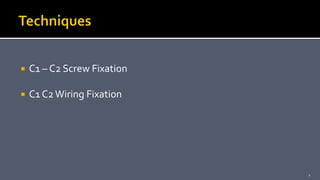
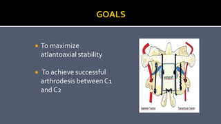
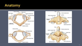
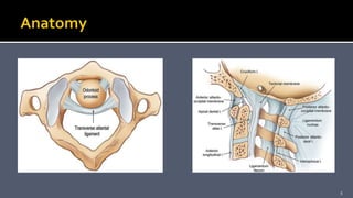
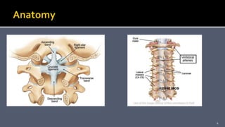
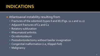
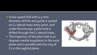
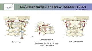
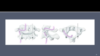
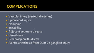
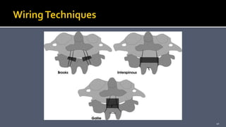
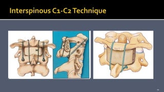


This document discusses surgical techniques for C1-C2 fixation, including posterior C1-C2 polyaxial screw and rod fixation, C1-C2 transarticular facet screws, and C1-C2 wiring fixation. It provides details on patient evaluation, surgical procedure, risks, and outcomes for each technique. Atlantoaxial instability can result from fractures, rheumatoid arthritis, or congenital anomalies and these fixation techniques are used to maximize stability and achieve arthrodesis between C1 and C2. Wiring techniques are less challenging than screw-based approaches but require an intact posterior arch and halo immobilization.


![CTEV [ clubfoot] DR ARUN LAL ,DR MOHAMED ASHRAF travancore medical college k...](https://cdn.slidesharecdn.com/ss_thumbnails/ctevclubfootdrarunlaldrmohamedashraftravancoremedicalcollegekollamkeralaindia-260208063247-18fc466c-thumbnail.jpg?width=640&height=640&fit=bounds)


![PERI-PROSTHETIC FRACTURE NAIL-PLATE CONSTRUCT [NPC].pptx](https://cdn.slidesharecdn.com/ss_thumbnails/drarunkumardrmohamedashrafperiprostheticfrasturenail-plateconstructnpc-260209164459-7e9d15a1-thumbnail.jpg?width=640&height=640&fit=bounds)

