This document discusses cellular system design fundamentals, including:
1. It provides an overview of key concepts like frequency reuse, cluster size, co-channel interference, and trunking.
2. It presents an example problem calculating the number of channels required per cell, number of subscribers served, and other metrics.
3. It gives another example comparing the spectral efficiency of digital and analog cellular systems using data on available bandwidth, coverage area, and interference ratios.
Orthogonal Frequency Division Multiplexing, OFDM uses a large number of narrow sub-carriers for multi-carrier transmission to overcome the effect of multi path fading problem. LTE uses OFDM for the downlink, from base station to terminal to transmit the data over many narrow band careers of 180 KHz each instead of spreading one signal over the complete 5MHz career bandwidth. OFDM meets the LTE requirement for spectrum flexibility and enables cost-efficient solutions for very wide carriers with high peak rates.
The primary advantage of OFDM over single-carrier schemes is its ability to cope with severe channel conditions. Channel equalization is simplified. The low symbol rate makes the use of a guard interval between symbols affordable, making it possible to eliminate inter symbol interference (ISI).
Broadside Array vs end-fire array
Higher directivity.
Provide increased directivity in
elevation and azimuth planes.
Generally used for reception.
Impedance match difficulty in
high power transmissions.
Variants are:
Horizontal Array of Dipoles
RCA Fishborne Antenna
Series Phase Array
This presentation is prepared for workshop session and is not in detail. You can ask your doubts here or you can email me at prakharbansal1@gmail.com. I'll try to answer to my best.
Transmission system used for optical fibers Jay Baria
In this presentation I have explained various types of transmission system used for optical transmission and also described about the budget method that has to be followed while selecting an source for optical fibers and also about the factors that should be consider while selecting an source.
There are several possible methods for increasing
transmission capacity over fixed bandwidth.
These include modulation employing different amplitude
levels, two orthogonal subcarriers and polarization.
In fact, the only remaining unused dimension is Space.
Multi user performance on mc cdma single relay cooperative system by distribu...IJCNCJournal
Increasing data rate and high performance is the target focus of wireless communication. The multi carrier on multi-hop communication system using relay's diversity technique which is supported by a reliable coding is a system that may give high performance. This research is developing a model of multi user and two scheme of multi carrier CDMA on multi hop communication system with diversity technique which is using Alamouti codes in Rayleigh fading channel. By Alamouti research, Space Time Block Code (STBC) for MIMO system can perform high quality signal at the receiver in the Rayleigh fading channel and the noisy system. In this research, MIMO by STBC is applied to single antenna system (Distributed-STBC/DSTBC) with multi carrier CDMA on multi hop wireless communication system (relay diversity) which is able to improve the received signal performance.
MC DS CDMA on multi hop wireless communication system with 2 hops is better performing than MC CDMA on multi user without Multi User Detector. To reach BER 10-3 multi hop system with MC CDMA needs more power 5 dB than MC DS CDMA at 5 users using Alamouti scheme for symbol transmission at the relay.
BER ENHANCEMENT OF MIMO-CDMA BASED ON SPACE-TIME BLOCK CODEScscpconf
Now a days, the demand for wireless communication systems with high data rates and high capacity has dramatically increased. CDMA (Code Division Multiple access) plays an important role in modern wireless communication systems. MIMO refers to links with multiple antennas at the transmitter and receiver side. CDMA with MIMO is a very promising technique beyond 3G and 4G wireless communications. The BER performance of MIMO-CDMA system depends on its spreading strategy. In this paper MIMO-CDMA system is designed with STBC (Space-Time Block Code) matrices for spreading. The proposed technique outperforms the tdesign permutation spreading method and also the conventional method. Simulation results shows that gain improvement with STBC approach as compared to other existing techniques.
Wireless communication now has been focus to increase data rate and high performance. The
multi carrier on multi-hop communication system using relay's diversity technique which is
supported by a reliable coding is a system that may give high performance.
This research is developing a model of multi carrier CDMA on multi hop communication
system with diversity technique which is using Alamouti codes in Rayleigh fading channel. By
Alamouti research, Space Time Block Code (STBC) for MIMO system can perform high quality
signal at the receiver in the Rayleigh fading channel and the noisy system. In this research,
MIMO by STBC is applied to single antenna system (Distributed-STBC/DSTBC) with multi
carrier CDMA on multi hop wireless communication system (relay diversity) which is able to
reduce the complexity of the system but the system performance even can be maintained and
improved.
MC CDMA on multi hop wireless communication system with 2 hops is performing much better
than Single Input Single Output (SISO) system (1 hop system). Power needed for 1 hop system to
have the same quality as 2 hops system to reach BER 10-3 is 12 dB. And multi hop system needs
orthogonal symbol to send from relay than original symbol to reach better performance. 12.5
dB power up is needed for multi hop system which sent same symbol as transmitter than relay
system which sent orthogonal symbol.
MC CDMA PERFORMANCE ON SINGLE RELAY COOPERATIVE SYSTEM BY DIVERSITY TECHNIQUE...cscpconf
Wireless communication now has been focus to increase data rate and high performance. The multi carrier on multi-hop communication system using relay's diversity technique which is
supported by a reliable coding is a system that may give high performance. This research is developing a model of multi carrier CDMA on multi hop communication system with diversity technique which is using Alamouti codes in Rayleigh fading channel. By Alamouti research, Space Time Block Code (STBC) for MIMO system can perform high quality signal at the receiver in the Rayleigh fading channel and the noisy system. In this research, MIMO by STBC is applied to single antenna system (Distributed-STBC/DSTBC) with multi carrier CDMA on multi hop wireless communication system (relay diversity) which is able to reduce the complexity of the system but the system performance even can be maintained andimproved.
MC CDMA on multi hop wireless communication system with 2 hops is performing much better than Single Input Single Output (SISO) system (1 hop system). Power needed for 1 hop system to have the same quality as 2 hops system to reach BER 10-3 is 12 dB. And multi hop system needs orthogonal symbol to send from relay than original symbol to reach better performance. 12.5 dB power up is needed for multi hop system which sent same symbol as transmitter than relay system which sent orthogonal symbol.
CHANNEL ESTIMATION AND MULTIUSER DETECTION IN ASYNCHRONOUS SATELLITE COMMUNIC...ijwmn
In this paper, we propose a new method of channel estimation for asynchronous additive white Gaussian noise channels in satellite communications. This method is based on signals correlation and multiuser interference cancellation which adopts a successive structure. Propagation delays and signals amplitudes are jointly estimated in order to be used for data detection at the receiver. As, a multiuser detector, a single stage successive interference cancellation (SIC) architecture is analyzed and integrated to the channel estimation technique and the whole system is evaluated. The satellite access method adopted is the direct sequence code division multiple access (DS CDMA) one. To evaluate the channel estimation and the detection technique, we have simulated a satellite uplink with an asynchronous multiuser access.
Energy-Efficient Target Coverage in Wireless Sensor Networks Based on Modifie...ijasuc
One of the major issues in Target-coverage problem of wireless sensor network is to increase the network
lifetime. This can be solved by selecting minimum working nodes that will cover all the targets. This
paper proposes a completely new method, in which minimum working node is selected by modified Ant
colony Algorithm. Experimental results show that the lever of algorithmic complication is depressed and
the searching time is reduced, and the proposed algorithm outperforms the other algorithm in terms.
Similar to Cellular system design fundamentals (20)
The Art of the Pitch: WordPress Relationships and SalesLaura Byrne
Clients don’t know what they don’t know. What web solutions are right for them? How does WordPress come into the picture? How do you make sure you understand scope and timeline? What do you do if sometime changes?
All these questions and more will be explored as we talk about matching clients’ needs with what your agency offers without pulling teeth or pulling your hair out. Practical tips, and strategies for successful relationship building that leads to closing the deal.
DevOps and Testing slides at DASA ConnectKari Kakkonen
My and Rik Marselis slides at 30.5.2024 DASA Connect conference. We discuss about what is testing, then what is agile testing and finally what is Testing in DevOps. Finally we had lovely workshop with the participants trying to find out different ways to think about quality and testing in different parts of the DevOps infinity loop.
Observability Concepts EVERY Developer Should Know -- DeveloperWeek Europe.pdfPaige Cruz
Monitoring and observability aren’t traditionally found in software curriculums and many of us cobble this knowledge together from whatever vendor or ecosystem we were first introduced to and whatever is a part of your current company’s observability stack.
While the dev and ops silo continues to crumble….many organizations still relegate monitoring & observability as the purview of ops, infra and SRE teams. This is a mistake - achieving a highly observable system requires collaboration up and down the stack.
I, a former op, would like to extend an invitation to all application developers to join the observability party will share these foundational concepts to build on:
UiPath Test Automation using UiPath Test Suite series, part 3DianaGray10
Welcome to UiPath Test Automation using UiPath Test Suite series part 3. In this session, we will cover desktop automation along with UI automation.
Topics covered:
UI automation Introduction,
UI automation Sample
Desktop automation flow
Pradeep Chinnala, Senior Consultant Automation Developer @WonderBotz and UiPath MVP
Deepak Rai, Automation Practice Lead, Boundaryless Group and UiPath MVP
PHP Frameworks: I want to break free (IPC Berlin 2024)Ralf Eggert
In this presentation, we examine the challenges and limitations of relying too heavily on PHP frameworks in web development. We discuss the history of PHP and its frameworks to understand how this dependence has evolved. The focus will be on providing concrete tips and strategies to reduce reliance on these frameworks, based on real-world examples and practical considerations. The goal is to equip developers with the skills and knowledge to create more flexible and future-proof web applications. We'll explore the importance of maintaining autonomy in a rapidly changing tech landscape and how to make informed decisions in PHP development.
This talk is aimed at encouraging a more independent approach to using PHP frameworks, moving towards a more flexible and future-proof approach to PHP development.
Builder.ai Founder Sachin Dev Duggal's Strategic Approach to Create an Innova...Ramesh Iyer
In today's fast-changing business world, Companies that adapt and embrace new ideas often need help to keep up with the competition. However, fostering a culture of innovation takes much work. It takes vision, leadership and willingness to take risks in the right proportion. Sachin Dev Duggal, co-founder of Builder.ai, has perfected the art of this balance, creating a company culture where creativity and growth are nurtured at each stage.
Accelerate your Kubernetes clusters with Varnish CachingThijs Feryn
A presentation about the usage and availability of Varnish on Kubernetes. This talk explores the capabilities of Varnish caching and shows how to use the Varnish Helm chart to deploy it to Kubernetes.
This presentation was delivered at K8SUG Singapore. See https://feryn.eu/presentations/accelerate-your-kubernetes-clusters-with-varnish-caching-k8sug-singapore-28-2024 for more details.
GraphRAG is All You need? LLM & Knowledge GraphGuy Korland
Guy Korland, CEO and Co-founder of FalkorDB, will review two articles on the integration of language models with knowledge graphs.
1. Unifying Large Language Models and Knowledge Graphs: A Roadmap.
https://arxiv.org/abs/2306.08302
2. Microsoft Research's GraphRAG paper and a review paper on various uses of knowledge graphs:
https://www.microsoft.com/en-us/research/blog/graphrag-unlocking-llm-discovery-on-narrative-private-data/
Elevating Tactical DDD Patterns Through Object CalisthenicsDorra BARTAGUIZ
After immersing yourself in the blue book and its red counterpart, attending DDD-focused conferences, and applying tactical patterns, you're left with a crucial question: How do I ensure my design is effective? Tactical patterns within Domain-Driven Design (DDD) serve as guiding principles for creating clear and manageable domain models. However, achieving success with these patterns requires additional guidance. Interestingly, we've observed that a set of constraints initially designed for training purposes remarkably aligns with effective pattern implementation, offering a more ‘mechanical’ approach. Let's explore together how Object Calisthenics can elevate the design of your tactical DDD patterns, offering concrete help for those venturing into DDD for the first time!
GDG Cloud Southlake #33: Boule & Rebala: Effective AppSec in SDLC using Deplo...James Anderson
Effective Application Security in Software Delivery lifecycle using Deployment Firewall and DBOM
The modern software delivery process (or the CI/CD process) includes many tools, distributed teams, open-source code, and cloud platforms. Constant focus on speed to release software to market, along with the traditional slow and manual security checks has caused gaps in continuous security as an important piece in the software supply chain. Today organizations feel more susceptible to external and internal cyber threats due to the vast attack surface in their applications supply chain and the lack of end-to-end governance and risk management.
The software team must secure its software delivery process to avoid vulnerability and security breaches. This needs to be achieved with existing tool chains and without extensive rework of the delivery processes. This talk will present strategies and techniques for providing visibility into the true risk of the existing vulnerabilities, preventing the introduction of security issues in the software, resolving vulnerabilities in production environments quickly, and capturing the deployment bill of materials (DBOM).
Speakers:
Bob Boule
Robert Boule is a technology enthusiast with PASSION for technology and making things work along with a knack for helping others understand how things work. He comes with around 20 years of solution engineering experience in application security, software continuous delivery, and SaaS platforms. He is known for his dynamic presentations in CI/CD and application security integrated in software delivery lifecycle.
Gopinath Rebala
Gopinath Rebala is the CTO of OpsMx, where he has overall responsibility for the machine learning and data processing architectures for Secure Software Delivery. Gopi also has a strong connection with our customers, leading design and architecture for strategic implementations. Gopi is a frequent speaker and well-known leader in continuous delivery and integrating security into software delivery.
GDG Cloud Southlake #33: Boule & Rebala: Effective AppSec in SDLC using Deplo...
Cellular system design fundamentals
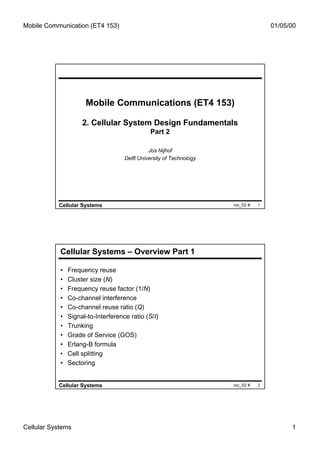
1. Mobile Communication (ET4 153) 01/05/00
Mobile Communications (ET4 153)
2. Cellular System Design Fundamentals
Part 2
Jos Nijhof
Delft University of Technology
Cellular Systems mc_02 # 1
Cellular Systems – Overview Part 1
• Frequency reuse
• Cluster size (N)
• Frequency reuse factor (1/N)
• Co-channel interference
• Co-channel reuse ratio (Q)
• Signal-to-Interference ratio (S/I)
• Trunking
• Grade of Service (GOS)
• Erlang-B formula
• Cell splitting
• Sectoring
Cellular Systems mc_02 # 2
Cellular Systems 1
2. Mobile Communication (ET4 153) 01/05/00
Cellular Systems – Overview Part 2
• Exercises on cellular planning
• Channel assignment strategies
• Handoff (handover) strategies
• Power control
Cellular Systems mc_02 # 3
Example 1.1 - Problem statement
(2)
(1) (5)
Compute:
66.7
30.8 (4) 38.2 (1) (a) The number of channels
(3) required in each cell
33.2 (7) (b) The number of subscribers
(6) 32.6
48.6 served by the system
(c) The average number of
37.8
subscribers per channel
Given: (d) The number of calls
Total available channels: 395 supported by the system
Each subscriber generates 0.03 erlang (e) The subscriber density per
Average holding time: 120 s square mile
System area: 1200 miles2
Grade of service: 2%
(f) The cell radius in miles
Cellular Systems mc_02 # 4
Cellular Systems 2
3. Mobile Communication (ET4 153) 01/05/00
Example 1.1 - Solution
Cell Traffic No. of No. of No. of Channel
Number (erlang) Channels Subscribers Calls Utilisation
Required Per Cell Per Cell
(An) (a) (b) (d)
1 30.8 40 1026.7 924 0.77
2 66.7 78 2223.3 2001 0.86
3 48.6 59 1620.0 1458 0.82
4 33.2 43 1106.7 996 0.77
5 38.2 48 1273.3 1146 0.80
6 37.8 48 1260.0 1134 0.79
7 32.6 42 1086.7 978 0.78
Total 287.9 358 9596.7 8637
From An An
erlang (b) x 0.9
0.03 (a)
table/chart
Cellular Systems mc_02 # 5
Example 1.1 - Solution
(a), (b) : see table
(c) : avg. number of subscriber s per channel : 9597 358 = 26.8
(d) : number of calls supported by system : A = λh ⇒ 0.03 = λ × 120
= 0.00025 [calls/s] = 0.00025 × 3600 = 0.9 [calls/hr ]
0.03
λ=
120
Cell (1) : Number of calls supported : 1026.7 × 0.9 = 924
(e) : subscriber density per mile 2 : 9597/1200 = 8.0
(f) : cell radius in miles : area/cell = 1200/7 = 171.4 miles 2 ⇒ radius
Cellular Systems mc_02 # 6
Cellular Systems 3
4. Mobile Communication (ET4 153) 01/05/00
Example 1.3 - Problem statement
Compare the spectral efficiency of the digital system with respect to the
analogue system using the following data:
(a) The total number of channels in the analogue cellular system = 416
(b) The number of control channels = 21
(c) The number of voice channels = 395
(d) The channel bandwidth = 30 kHz. The digital systems has 3 channels
per 30 kHz
(e) The reuse factor N = 7
(f) The total available bandwidth in each direction = 12.5 MHz
(g) The total coverage area = 10,000 km2
(h) The required S/I ratio for the analogue system = 18 dB (63.1)
(I) The required S/I ratio for the digital system = 14 dB (25.1)
(j) The call blocking (GOS) = 2%
Cellular Systems mc_02 # 7
Example 1.3 - Solution
Spectral efficiency - η m =
( Total traffic carried by the system )
( Bandwidth ) × ( Total coverage area)
ANALOGUE SYSTEM:
No. of voice channels / cell: 395 / 7 = 56.4 ⇒ 56
Offered traffic load: N = 56, B = 0.02 ⇒ A = 459 (from erlang table)
.
Carried traffic load: C = (1 − B) × A = (1 − 0.02) × 45.9 = 44.98 [erlang / cell]
10,000 10,000
Number of cells: =
Acell 2.6 R 2
10,000
44.98 ×
⇒ Spectral efficiency = 2.6 R 2 = 1384
.
12.5 × 10,000 R2
Cellular Systems mc_02 # 8
Cellular Systems 4
5. Mobile Communication (ET4 153) 01/05/00
Example 1.3 - Solution
Total traffic carried by the system
Spectral efficiency = ηm =
(Bandwidth ) × (Total coverage area )
DIGITAL SYSTEM :
No. of channels per 30 kHz = 3
Number of voice channels per cell = 56 × 3 = 168
Offered traffic load : N = 168,B = 0.02 ⇒ A = 154.5 (from erlang table)
Carried traffic load : C = (1 − B ) × A = (1 − 0.02 ) × 154.5 [erlang/cel l]
1 1
S 4 S 2 Qdigital 2 25.1
Q = 6 ⇒ Q = 6 ⇒
2
= = 0.6307
I I Qanaloge 2
63.1
151.4 7.386
⇒ Spectral efficiency = = erlang/MHz /km 2
12.5 × 2.6 R × 0.6307
2
R 2
ηm (digital ) 7.386
⇒ = = 5.34
ηm (analogue ) 1.384
Cellular Systems mc_02 # 9
GSM system architecture (1)
PLMN
& International
OMC
ISC
PSTN
ISDN
PDN
MS BTS
BSC
GMSC
BSC MSC
BTS
MS
EIR
MS AUC
BTS HLR
VLR
Cellular Systems mc_02 # 10
Cellular Systems 5
6. Mobile Communication (ET4 153) 01/05/00
GSM system architecture (2)
BTS Base Transceiving Station
BSC Base Station Controller
MSC Mobile Switching Center
GMSC Gateway MSC
ISC International Switching Center
MS Mobile Station
HLR Home Location Register
VLR Visitor Location Register
EIR Equipment Identity Register
AUC Authentication Center
OMC Operation and Maintenance Center
Cellular Systems mc_02 # 11
A mobile radio environment
Multipath fading
Ra
dio
pa
th Medium
Pro
pa
g
los ation
s
Base
station
Mobile
station
Cellular Systems mc_02 # 12
Cellular Systems 6
7. Mobile Communication (ET4 153) 01/05/00
The mobile radio channel: fading
10
Shadowing
0
Signal Level (dB)
-10
-20
-30
Rayleigh fading
-40 (multipath reception)
λ
-50
2
-60
0 1 2 3 4 5 6 7
time
Cellular Systems mc_02 # 13
GSM: Carrier frequencies, duplexing, and TDMA frames
960 MHz
959.8 MHz 124
123 Downlink
25 MHz
⋅⋅⋅
1 2 3 4 5 6 7 8
200 kHz ⋅⋅⋅
2
935.2 MHz 1
935 MHz
Data burst, 156.25 bit periods = 15/26 ms ≈ 576.9 µs
915 MHz
914.8 MHz 124
45 MHz 123 Delay
separation 1 2 3 4 5 6 7 8
⋅⋅⋅
200 kHz ⋅⋅⋅ Uplink
2
890.2 MHz 1
890 MHz
Cellular Systems mc_02 # 14
Cellular Systems 7
8. Mobile Communication (ET4 153) 01/05/00
Channel Assignment Strategies (1)
• Fixed channel allocation (FCA)
– fixed assignment of frequencies to cell clusters and
cells.
– not very efficient if traffic load varies
– simple to use, but requires careful traffic analysis
before installation
– used in the GSM system
• Variation: Borrowing channel allocation (BCA)
– heavy loaded cell can “borrow” channels from a light
loaded neighboring cell
– problem: interference
Cellular Systems mc_02 # 15
Channel Assignment Strategies (2)
• Dynamic channel allocation (DCA)
– each time a call request is made, the base station
requests a channel from the MSC
– MSC takes into account:
• probability of future blocking within the cell
• frequency of use of the channel
• frequency reuse distance
– Advantages:
• lower probability of blocking, increases trunking capacity of
the system
– Disadvantages:
• increased storage and computational load
Cellular Systems mc_02 # 16
Cellular Systems 8
9. Mobile Communication (ET4 153) 01/05/00
The handover process
Handover: Changing physical channels, radio channels of fixed
network connections involved in a call, while
maintaining the call
Two phases:
1. MONITORING PHASE
• measurement of the quality of the current and
possible candidate radio links
• initiation of a handover when necessary
2. HANOVER HANDLING PHASE
• determination of a new point of attachment (PoA)
• setting up of new links, release of old links
• initiation of a possible re-routing procedure
Cellular Systems mc_02 # 17
Two basic reasons for a handover
• MS moves out of the range of a BTS
– signal level becomes too low
– error rate becomes too high
• Load balancing
– traffic in one cell is too high ⇒ shift some MSs to other
cells with a lower load
The GSM standard identifies about 40 reasons for a handover!
Cellular Systems mc_02 # 18
Cellular Systems 9
10. Mobile Communication (ET4 153) 01/05/00
Handover types
• Intra-cell handover
– narrow-band interference ⇒ change carrier frequency
– controlled by BSC
• Inter-cell, intra-BSC handover
– typical handover scenario
– BSC performs the handover, assigns new radio channel in the
new cell, releases the old one
• Inter-BSC, intra-MSC handover
– handover between cells controlled by different BSCs
– controlled by the MSC
• Inter-MSC handover
– handover between cells belonging to different MSCs
– controlled by both MSCs
Cellular Systems mc_02 # 19
Handover types
PLMN
MSC MSC MSC
MSC
BSC BSC BSC BSC BSC
old handover new handover
PoA PoA
handover
Intra-BSC handover Inter-BSC / intra-MSC Inter-MSC handover
handover
Cellular Systems mc_02 # 20
Cellular Systems 10
11. Mobile Communication (ET4 153) 01/05/00
Intra-MSC handover (mobile assisted)
MS BTSold BSCold MSC BSCnew BTSnew
measurement measurement
report result HO required
HO decision ch. activation
HO request
resource allocation
HO request ack ch. activation ack
HO command HO command
HO command
HO access
Link establishment
HO complete HO complete
clear command clear command
clear complete clear complete
Cellular Systems mc_02 # 21
Handover scenario at cell boundary
Level at point A
Received signal level
Improper Handoff threshold
handover situation Minimum acceptable signal level
Level at point B
Received signal level
Level at point B
Proper
handover situation Level at which handover is made
BS1 A B BS2
Cellular Systems mc_02 # 22
Cellular Systems 11
12. Mobile Communication (ET4 153) 01/05/00
Handover decision depending on receive level
receive level receive level
BTSold BTSnew
average level
HO_MARGIN
MS MS
BTSold BTSnew
Cellular Systems mc_02 # 23
Handover – 1st generation systems
• 1st generation systems (analog cellular):
– signal strength measurements made by the BSs and
supervised by the MSC
– the BS constantly monitors the signal strengths of all
the voice channels
– locator receiver measures signal strength of MSs in
neighboring cells
– MSC decides if a handover is necessary or not.
Cellular Systems mc_02 # 24
Cellular Systems 12
13. Mobile Communication (ET4 153) 01/05/00
Handover – 2nd generation systems
• 2nd generation systems (digital TDMA):
– handover decisions are mobile assisted
– every MS measures the received power from
surrounding BSs and sends reports to its own BS
– handover is initiated when the power received from a
neighbor BS begins to exceed the power from the
current BS (by a certain level and/or for a certain
period)
Cellular Systems mc_02 # 25
Avoiding handovers: Umbrella cells
Small microcells for
low speed traffic
Large “umbrella” cell for
high speed traffic
Cellular Systems mc_02 # 26
Cellular Systems 13
14. Mobile Communication (ET4 153) 01/05/00
Power control
• Power levels transmitted by every MS are under
constant control by the BSC.
• Assures that each MS within a BTS coverage area
provides the same signal level to the BTS
receiver.
• Goals:
– to reduce interference
– to prolong battery life
– to combat the near-far problem in CDMA systems
Cellular Systems mc_02 # 27
Cellular Systems 14