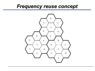
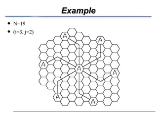
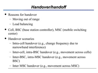
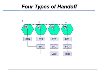
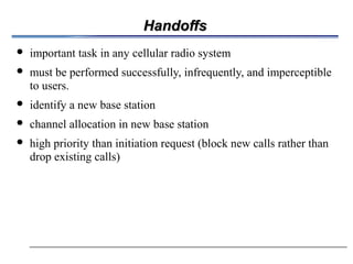
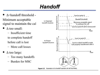
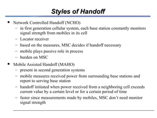
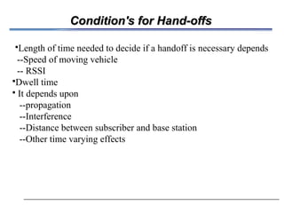
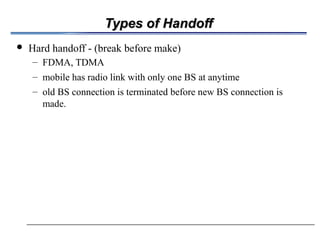
Cellular ConceptCellular Concept
 The limited capacity of the first mobile radio-telephone services was related
to the spectrum used…not much sharing and a lot of bandwidth dedicated to
a single call.
– good coverage
– interference: impossible to reuse the same frequency
 The cellular concept addressed many of the shortcomings of the first mobile
telephones
– Frequency reuse
– Wasted spectrum allocated to a single user
 In 1968, Bell Labs proposed the cellular telephony concept to the FCC
 It was approved and then the work began!
– FCC allocated spectrum (took away TV UHF channels 70-83) in the
825-845 MHz and 870-890 MHz bands
– AT&T put up a developmental system in Chicago
Cellular ConceptCellular Concept
 developed by Bell Labs 1960’s-70’s
 areas divided into cells
 a system approach, no major technological changes
 a few hundred meters in some cities,
 each served by base station with lower power transmitter
 each gets portion of total number of channels
 neighboring cells assigned different groups of channels,
interference minimized
 hexagon geometry cell shape
Frequency reuse conceptFrequency reuse concept
Frequency ReuseFrequency Reuse
 Adjacent cells assigned different frequencies to avoid
interference or crosstalk
 Objective is to reuse frequency in nearby cells
– 10 to 50 frequencies assigned to each cell
– transmission power controlled to limit power at that frequency
escaping to adjacent cells
– the issue is to determine how many cells must intervene between
two cells using the same frequency
Frequency ReuseFrequency Reuse
 each cell allocated a group k channels
– a cluster has N cells with unique and disjoint channel
 groups, N typically 4, 7, 12
 total number of duplex channels S = kN
 Cluster repeated M times in a system
 Total number of channels that can be used (capacity)
– C = MkN = MS
 Smaller cells  higher M  higher C
+ Channel reuse  higher capacity
+ Lower power requirements for mobiles
– Additional base stations required
– More frequent handoffs
Effect of cluster size NEffect of cluster size N
 channels unique in same cluster, repeated over clusters
 keep cell size same
– large N : weaker interference, but lower capacity
– small N: higher capacity, more interference need to maintain
certain S/I level
 frequency reuse factor: 1/N
– each cell within a cluster assigned 1/N of the total available
channels
 In most of the current networks, frequency reuse factor is 1.
Design of cluster sizeDesign of cluster size
 In order to connect without gaps between adjacent cells
 N = i2
+ ij + j2
where i and j are non-negative integers
 Example i = 2, j = 1
– N = 22
+ 2(1) + 12
= 4 + 2 + 1 = 7
 Next page example
– move i cells along any chain or hexagon.
– then turn 60 degrees counterclockwise and move j cel
ExampleExample
 N=19
 (i=3, j=2)
Handover/handoffHandover/handoff
 Reasons for handover
– Moving out of range
– Load balancing
 Cell, BSC (base station controller), MSC (mobile switching
center)
 Handover scenarios
– Intra-cell handover (e.g., change frequency due to
narrowband interference)
– Inter-cell, intra-BSC handover (e.g., movement across cells)
– Inter-BSC, intra-MSC handover (e.g., movement across
BSC)
– Inter MSC handover (e.g., movement across MSC)
Four Types of HandoffFour Types of Handoff
MSC MSC
BSC BSCBSC
BTS BTS BTSBTS
MS MS MS MS
1
2 3 4
HandoffsHandoffs
 important task in any cellular radio system
 must be performed successfully, infrequently, and imperceptible
to users.
 identify a new base station
 channel allocation in new base station
 high priority than initiation request (block new calls rather than
drop existing calls)
HandoffHandoff
 ∆=handoff threshold -
Minimum acceptable
signal to maintain the call
 ∆ too small:
– Insufficient time
to complete handoff
before call is lost
– More call losses
 ∆ too large:
– Too many handoffs
– Burden for MSC
Styles of HandoffStyles of Handoff
 Network Controlled Handoff (NCHO)
– in first generation cellular system, each base station constantly monitors
signal strength from mobiles in its cell
– Locator receiver
– based on the measures, MSC decides if handoff necessary
– mobile plays passive role in process
– burden on MSC
 Mobile Assisted Handoff (MAHO)
– present in second generation systems
– mobile measures received power from surrounding base stations and
report to serving base station
– handoff initiated when power received from a neighboring cell exceeds
current value by a certain level or for a certain period of time
– faster since measurements made by mobiles, MSC don’t need monitor
signal strength
Condition's for Hand-offsCondition's for Hand-offs
Length of time needed to decide if a handoff is necessary depends
--Speed of moving vehicle
-- RSSI
Dwell time
 It depends upon
--propagation
--Interference
--Distance between subscriber and base station
--Other time varying effects
Types of HandoffTypes of Handoff
 Hard handoff - (break before make)
– FDMA, TDMA
– mobile has radio link with only one BS at anytime
– old BS connection is terminated before new BS connection is
made.
Types of HandoffTypes of Handoff
 Soft handoff (make before break)
– CDMA systems
– mobile has simultaneous radio link with more than one BS at any
time
– new BS connection is made before old BS connection is broken
– mobile unit remains in this state until one base station clearly
predominates
Types of HandoffTypes of Handoff
 Vertical handoff
Interference and System CapacityInterference and System Capacity
 major limiting factor in performance of cellular radio systems
 sources of interference:
– other mobiles in same cell
– a call in progress in a neighboring cell
– other base stations operating in the same frequency band
– Non-cellular system leaking energy into the cellular frequency
band
 effect of interference:
– voice channel: cross talk
– More Severe in urban areas due to large number of base stations
and mobiles.
– control channel: missed or blocked calls
 two main types:
– co-channel interference ,adjacent channel interference
Co-Channel InterferenceCo-Channel Interference
 cells that use the same set of frequencies are called co-channel
cells.
 Interference between the cells is called co-channel interference.
 Co-channel reuse ratio: Q = D/R=sqrt(3N)
– R: radius of cell
– D: distance between nearest co-channel cells
 Small Q  small cluster size N  large capacity
 large Q  good transmission quality means less interference
 tradeoff must be made in actual cellular design
Co-channel Reuse RatioCo-channel Reuse Ratio
 SINR Power
propagation
factor 2-6∑
=
=
0
1
i
i
iI
S
I
S






−=






=
−
0
0
log10)()(
d
d
dBmPdBmP
d
d
PP
tr
tr
α
α
Cochannel Interference
 Assuming transmission power of each base station is
equal and n is same for whole coverage area.
 Approximation
 AMPS example
α=4, S/I=18dB, N needs to be larger than 6.49.
00
1
)3()/(
)(
0
i
N
i
RD
D
R
I
S
i
i
i
αα
α
α
===
∑=
−
−
Adjacent Channel InterferenceAdjacent Channel Interference
 Interference resulting from signals where are adjacent in
frequency to the desired signal.
 Due to imperfect receiver filters that allow
nearby frequencies to leak into pass band.
 Can be minimized by careful filtering and assignments, and by
keeping frequency separation between channel in a given cell as
large as possible, the adjacent channel interference may be
reduced considerably.

Cellular concept

  • 1.
    Cellular ConceptCellular Concept The limited capacity of the first mobile radio-telephone services was related to the spectrum used…not much sharing and a lot of bandwidth dedicated to a single call. – good coverage – interference: impossible to reuse the same frequency  The cellular concept addressed many of the shortcomings of the first mobile telephones – Frequency reuse – Wasted spectrum allocated to a single user  In 1968, Bell Labs proposed the cellular telephony concept to the FCC  It was approved and then the work began! – FCC allocated spectrum (took away TV UHF channels 70-83) in the 825-845 MHz and 870-890 MHz bands – AT&T put up a developmental system in Chicago
  • 2.
    Cellular ConceptCellular Concept developed by Bell Labs 1960’s-70’s  areas divided into cells  a system approach, no major technological changes  a few hundred meters in some cities,  each served by base station with lower power transmitter  each gets portion of total number of channels  neighboring cells assigned different groups of channels, interference minimized  hexagon geometry cell shape
  • 3.
  • 4.
    Frequency ReuseFrequency Reuse Adjacent cells assigned different frequencies to avoid interference or crosstalk  Objective is to reuse frequency in nearby cells – 10 to 50 frequencies assigned to each cell – transmission power controlled to limit power at that frequency escaping to adjacent cells – the issue is to determine how many cells must intervene between two cells using the same frequency
  • 5.
    Frequency ReuseFrequency Reuse each cell allocated a group k channels – a cluster has N cells with unique and disjoint channel  groups, N typically 4, 7, 12  total number of duplex channels S = kN  Cluster repeated M times in a system  Total number of channels that can be used (capacity) – C = MkN = MS  Smaller cells  higher M  higher C + Channel reuse  higher capacity + Lower power requirements for mobiles – Additional base stations required – More frequent handoffs
  • 6.
    Effect of clustersize NEffect of cluster size N  channels unique in same cluster, repeated over clusters  keep cell size same – large N : weaker interference, but lower capacity – small N: higher capacity, more interference need to maintain certain S/I level  frequency reuse factor: 1/N – each cell within a cluster assigned 1/N of the total available channels  In most of the current networks, frequency reuse factor is 1.
  • 7.
    Design of clustersizeDesign of cluster size  In order to connect without gaps between adjacent cells  N = i2 + ij + j2 where i and j are non-negative integers  Example i = 2, j = 1 – N = 22 + 2(1) + 12 = 4 + 2 + 1 = 7  Next page example – move i cells along any chain or hexagon. – then turn 60 degrees counterclockwise and move j cel
  • 8.
  • 9.
    Handover/handoffHandover/handoff  Reasons forhandover – Moving out of range – Load balancing  Cell, BSC (base station controller), MSC (mobile switching center)  Handover scenarios – Intra-cell handover (e.g., change frequency due to narrowband interference) – Inter-cell, intra-BSC handover (e.g., movement across cells) – Inter-BSC, intra-MSC handover (e.g., movement across BSC) – Inter MSC handover (e.g., movement across MSC)
  • 10.
    Four Types ofHandoffFour Types of Handoff MSC MSC BSC BSCBSC BTS BTS BTSBTS MS MS MS MS 1 2 3 4
  • 11.
    HandoffsHandoffs  important taskin any cellular radio system  must be performed successfully, infrequently, and imperceptible to users.  identify a new base station  channel allocation in new base station  high priority than initiation request (block new calls rather than drop existing calls)
  • 12.
    HandoffHandoff  ∆=handoff threshold- Minimum acceptable signal to maintain the call  ∆ too small: – Insufficient time to complete handoff before call is lost – More call losses  ∆ too large: – Too many handoffs – Burden for MSC
  • 13.
    Styles of HandoffStylesof Handoff  Network Controlled Handoff (NCHO) – in first generation cellular system, each base station constantly monitors signal strength from mobiles in its cell – Locator receiver – based on the measures, MSC decides if handoff necessary – mobile plays passive role in process – burden on MSC  Mobile Assisted Handoff (MAHO) – present in second generation systems – mobile measures received power from surrounding base stations and report to serving base station – handoff initiated when power received from a neighboring cell exceeds current value by a certain level or for a certain period of time – faster since measurements made by mobiles, MSC don’t need monitor signal strength
  • 14.
    Condition's for Hand-offsCondition'sfor Hand-offs Length of time needed to decide if a handoff is necessary depends --Speed of moving vehicle -- RSSI Dwell time  It depends upon --propagation --Interference --Distance between subscriber and base station --Other time varying effects
  • 15.
    Types of HandoffTypesof Handoff  Hard handoff - (break before make) – FDMA, TDMA – mobile has radio link with only one BS at anytime – old BS connection is terminated before new BS connection is made.
  • 16.
    Types of HandoffTypesof Handoff  Soft handoff (make before break) – CDMA systems – mobile has simultaneous radio link with more than one BS at any time – new BS connection is made before old BS connection is broken – mobile unit remains in this state until one base station clearly predominates
  • 17.
    Types of HandoffTypesof Handoff  Vertical handoff
  • 18.
    Interference and SystemCapacityInterference and System Capacity  major limiting factor in performance of cellular radio systems  sources of interference: – other mobiles in same cell – a call in progress in a neighboring cell – other base stations operating in the same frequency band – Non-cellular system leaking energy into the cellular frequency band  effect of interference: – voice channel: cross talk – More Severe in urban areas due to large number of base stations and mobiles. – control channel: missed or blocked calls  two main types: – co-channel interference ,adjacent channel interference
  • 19.
    Co-Channel InterferenceCo-Channel Interference cells that use the same set of frequencies are called co-channel cells.  Interference between the cells is called co-channel interference.  Co-channel reuse ratio: Q = D/R=sqrt(3N) – R: radius of cell – D: distance between nearest co-channel cells  Small Q  small cluster size N  large capacity  large Q  good transmission quality means less interference  tradeoff must be made in actual cellular design
  • 20.
    Co-channel Reuse RatioCo-channelReuse Ratio  SINR Power propagation factor 2-6∑ = = 0 1 i i iI S I S       −=       = − 0 0 log10)()( d d dBmPdBmP d d PP tr tr α α
  • 21.
    Cochannel Interference  Assumingtransmission power of each base station is equal and n is same for whole coverage area.  Approximation  AMPS example α=4, S/I=18dB, N needs to be larger than 6.49. 00 1 )3()/( )( 0 i N i RD D R I S i i i αα α α === ∑= − −
  • 22.
    Adjacent Channel InterferenceAdjacentChannel Interference  Interference resulting from signals where are adjacent in frequency to the desired signal.  Due to imperfect receiver filters that allow nearby frequencies to leak into pass band.  Can be minimized by careful filtering and assignments, and by keeping frequency separation between channel in a given cell as large as possible, the adjacent channel interference may be reduced considerably.