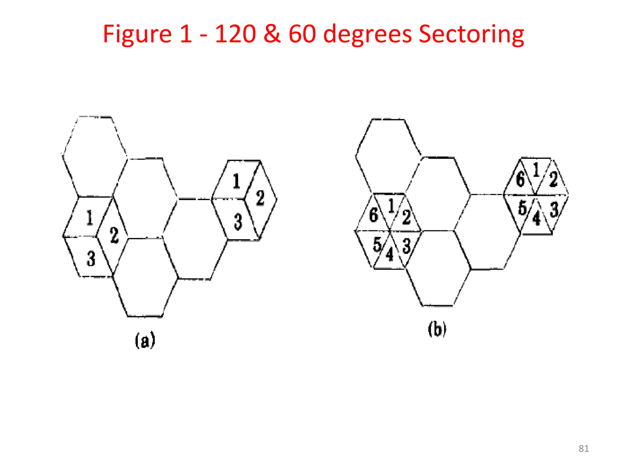
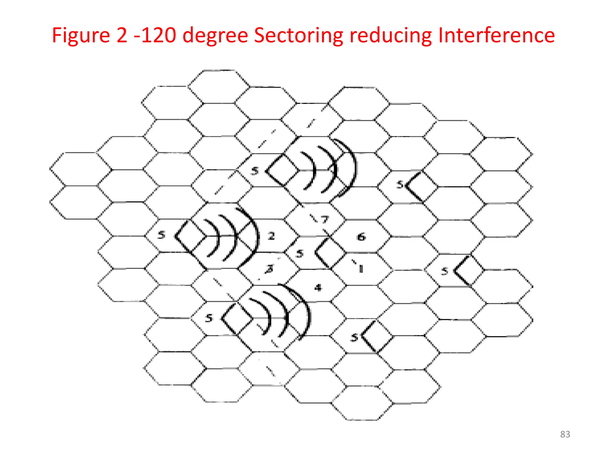
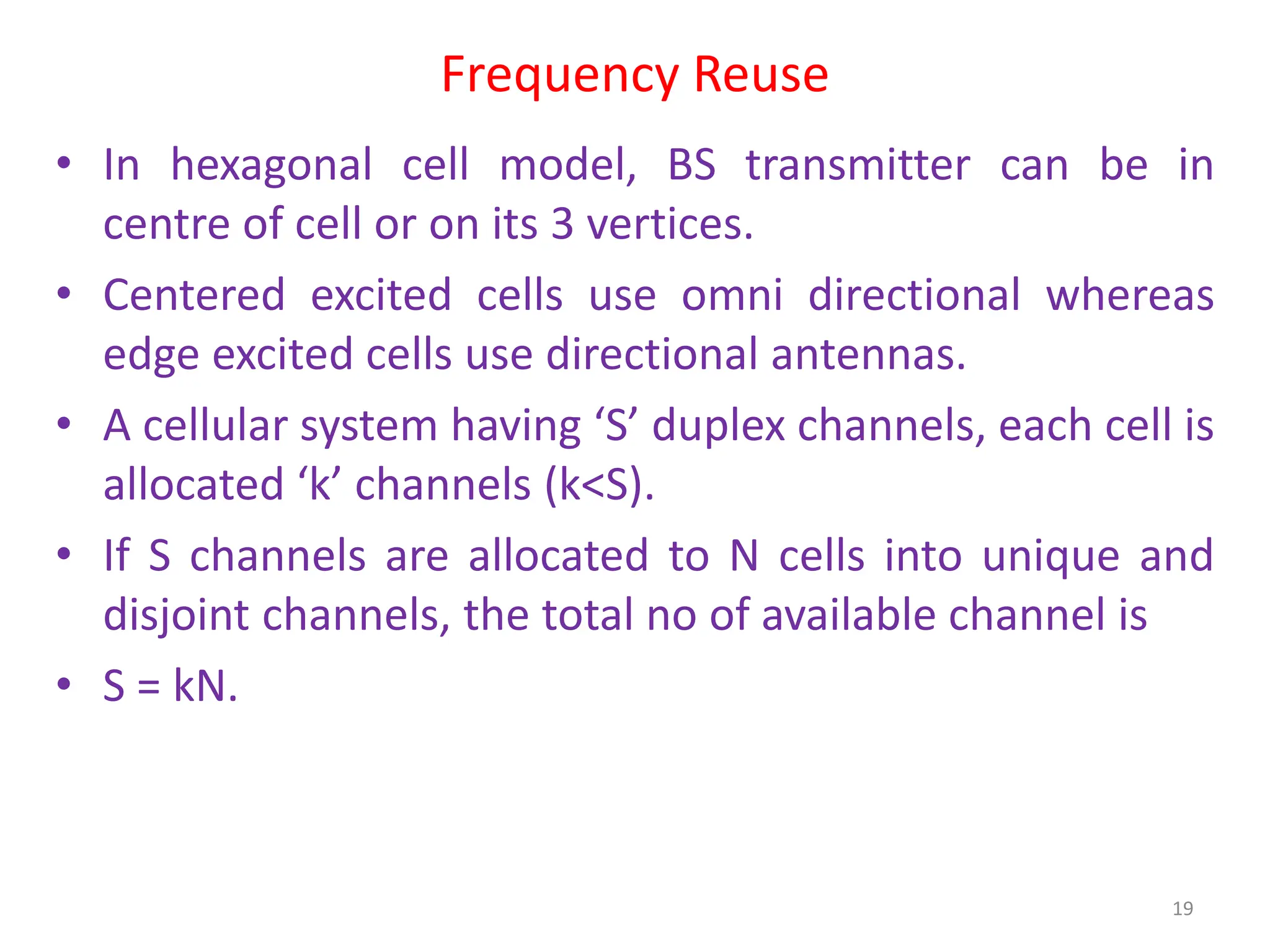
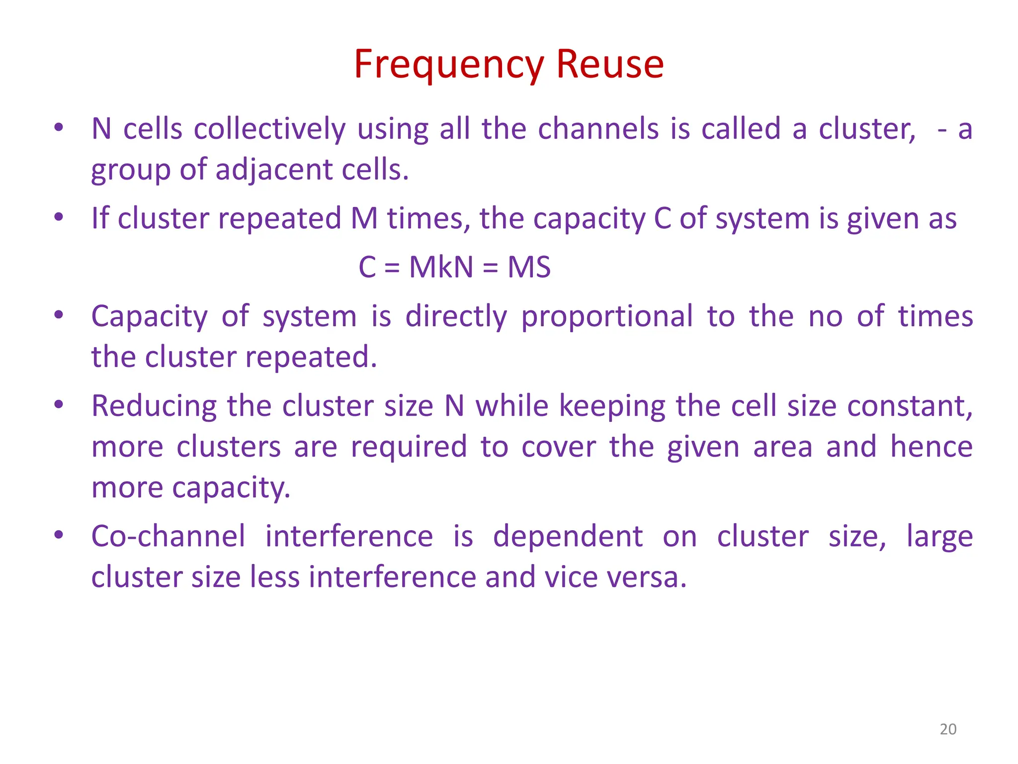
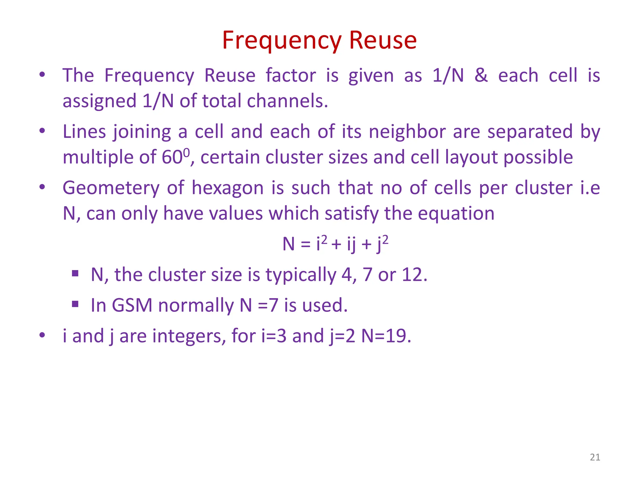
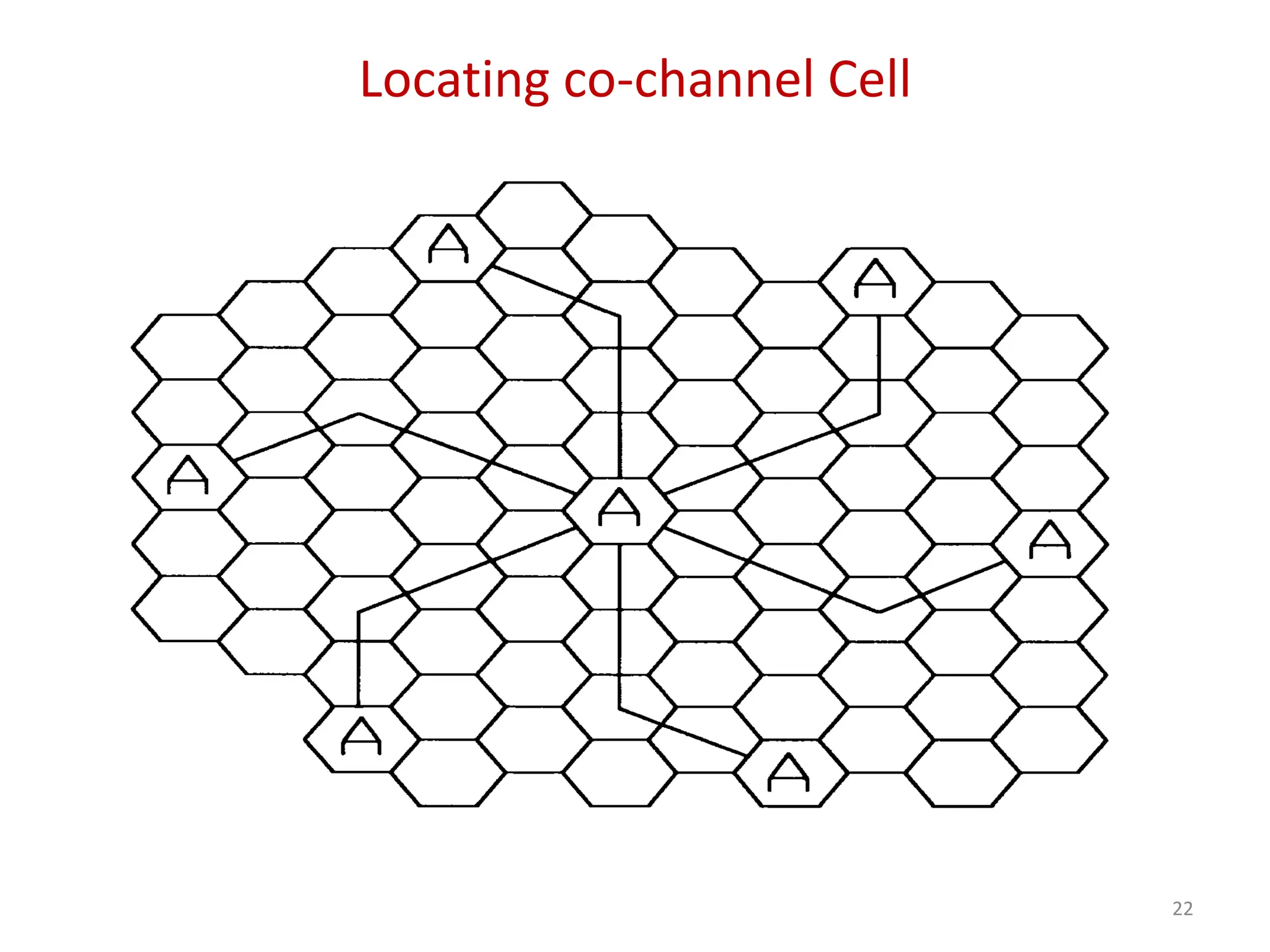
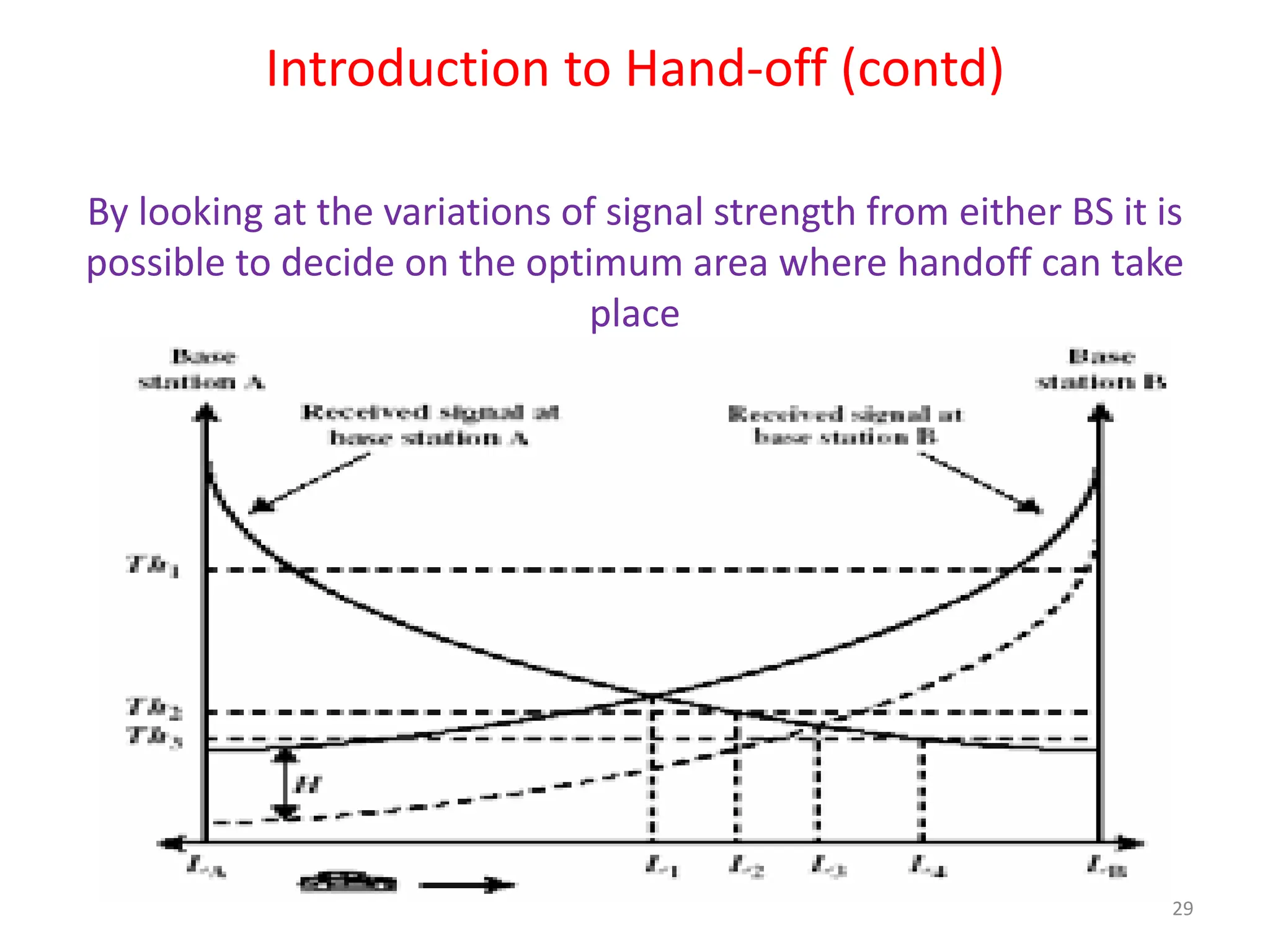
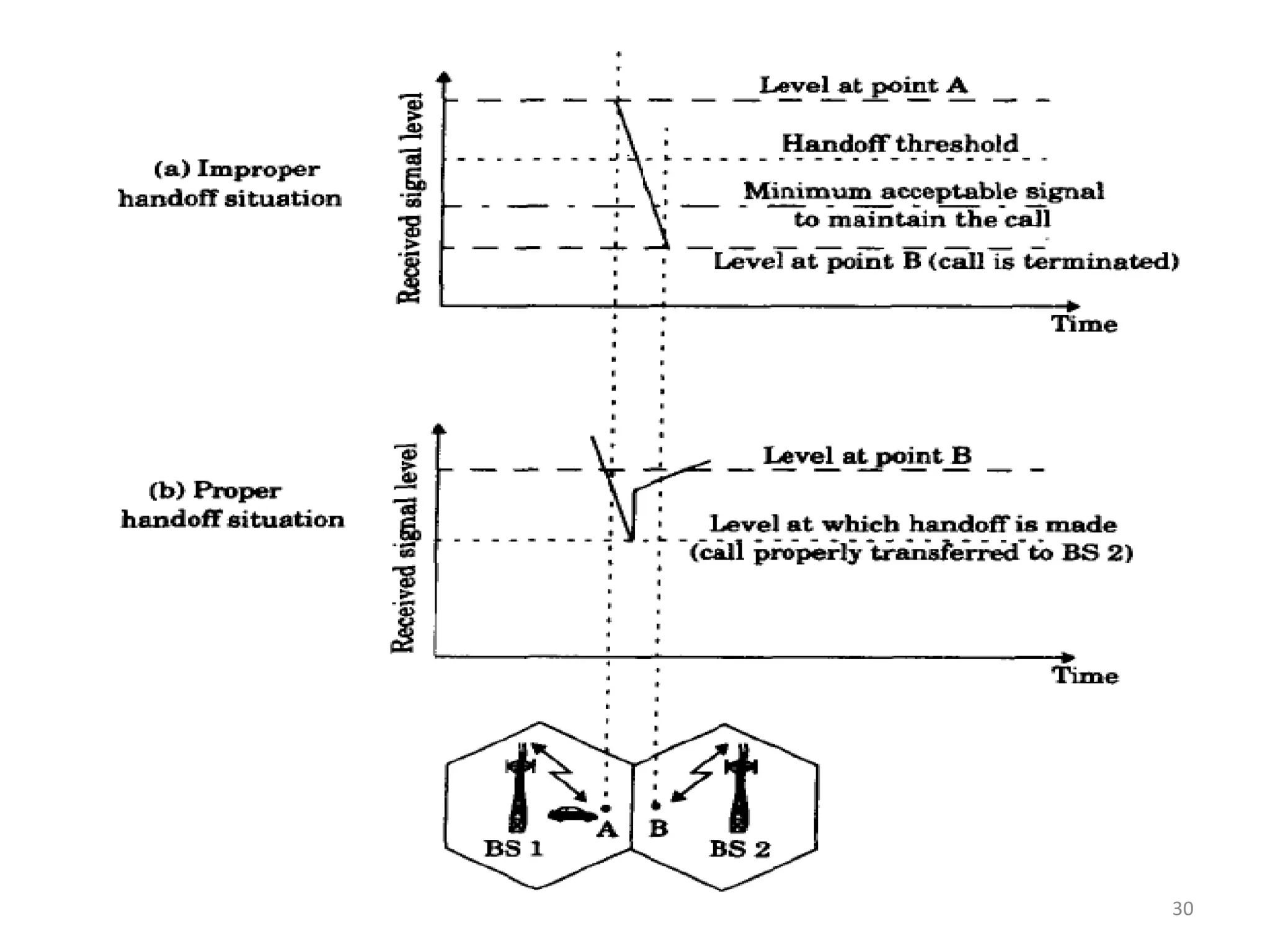
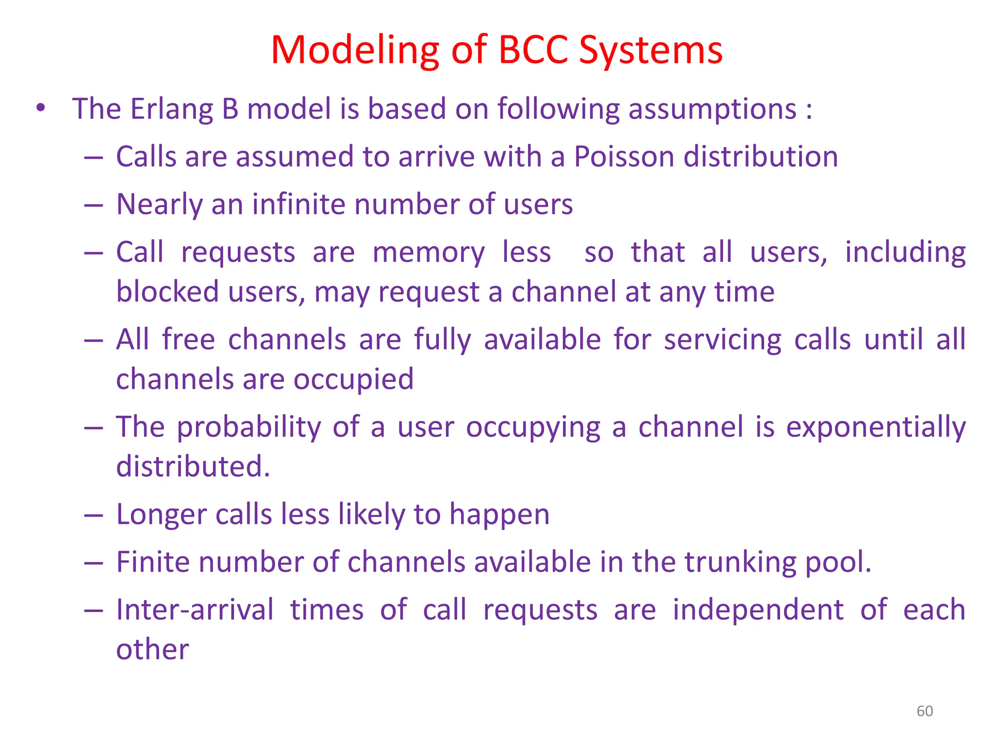
The document outlines the principles and strategies of mobile communication systems, focusing on concepts such as frequency reuse, channel assignment strategies, handoff procedures, and interference management. It discusses the limitations of older systems like 2G and 2.5G while presenting design approaches for 3G and future mobile communication technologies. Key topics include the importance of frequency reuse for capacity enhancement and the role of handoff strategies in maintaining call quality as users move between cells.


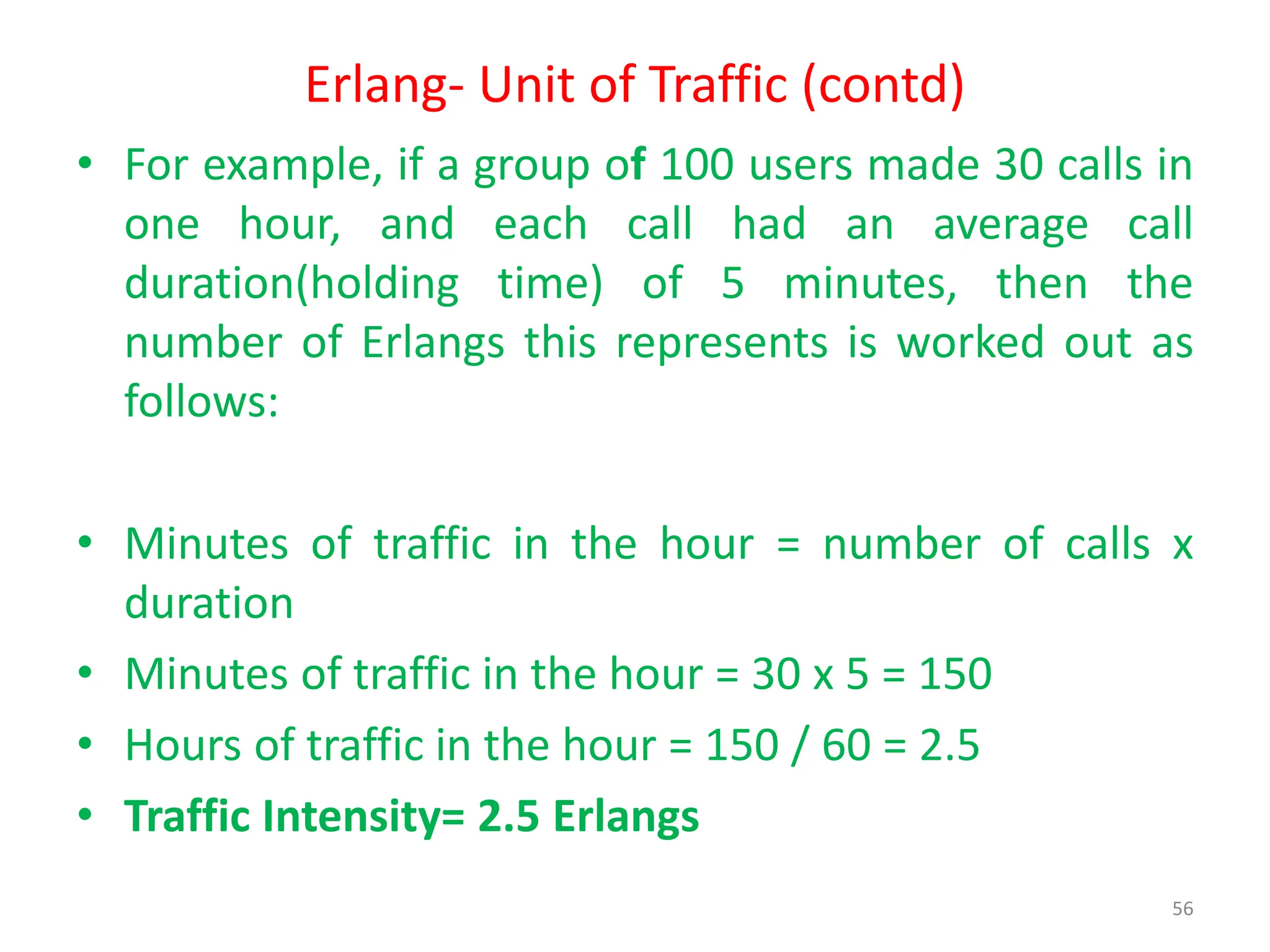
![Modeling of BCC Systems (contd)
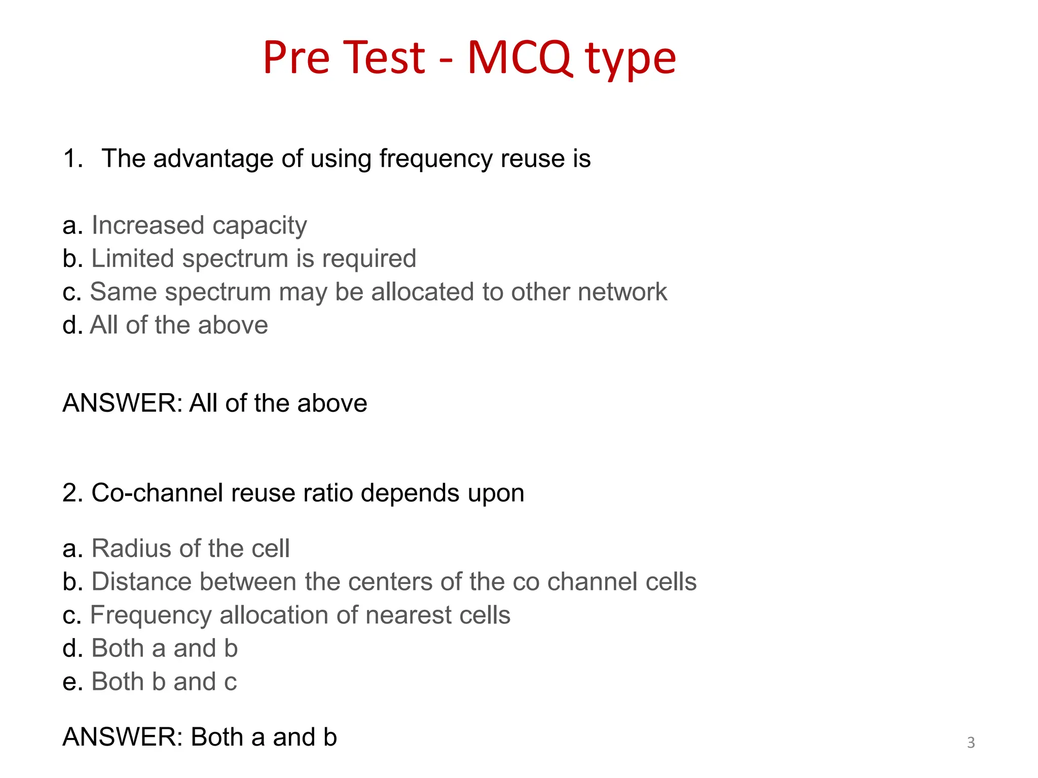
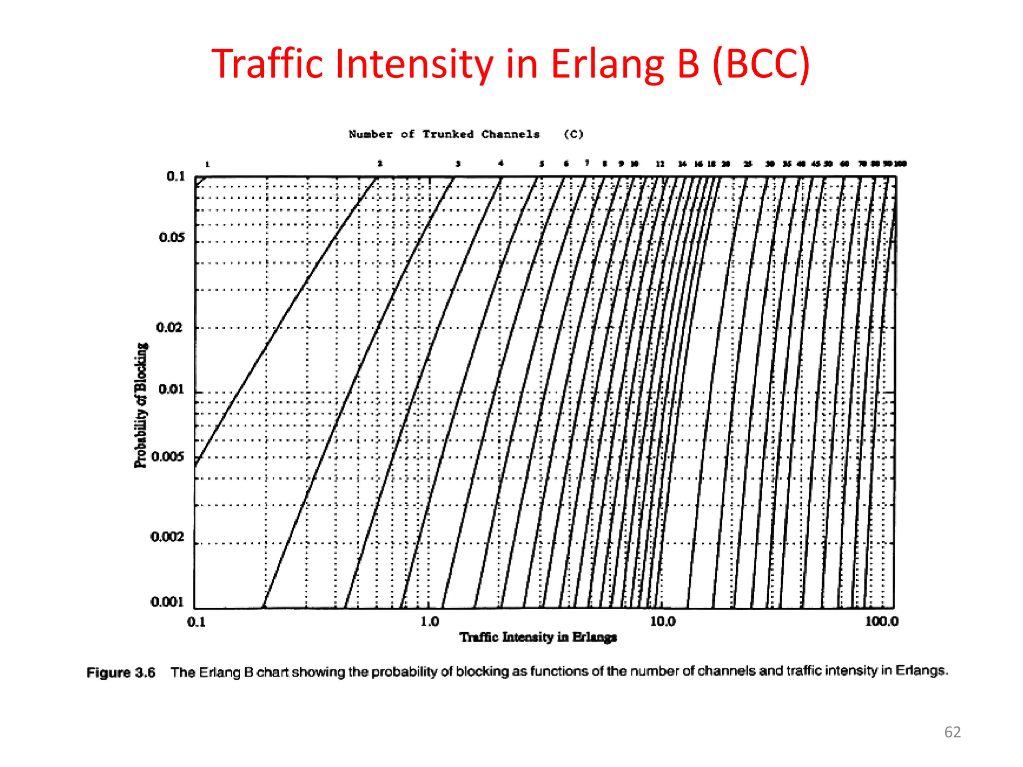
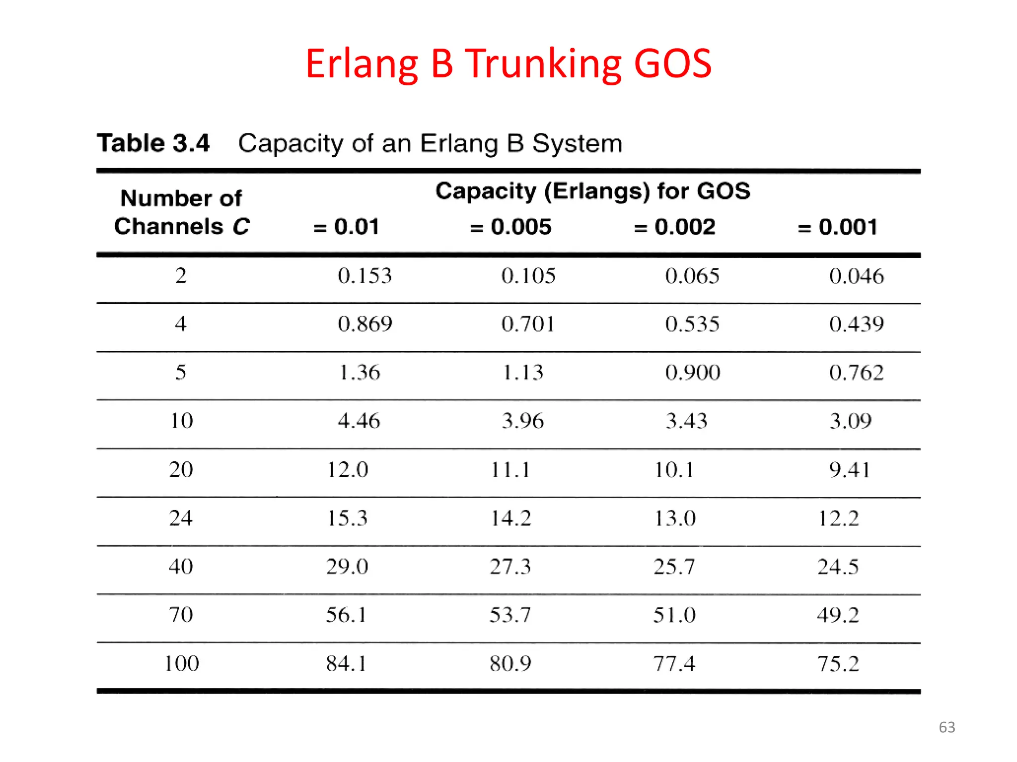
• Erlang B formula is given by
• where ‘C’ is the number of trunked channels offered by
a trunked radio system.
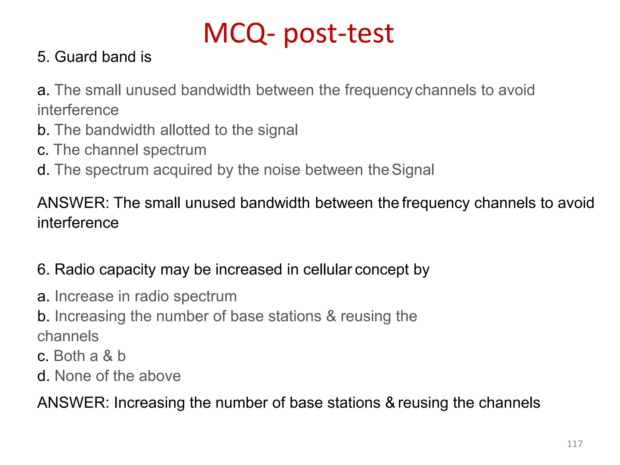
• ‘A’ is the total offered traffic.
61
Pr [blocking] = (AC/C ! )](https://image.slidesharecdn.com/mobilecommunication-240714081448-6a931d75/75/MobileCommunication-related-document-pdf-61-2048.jpg)
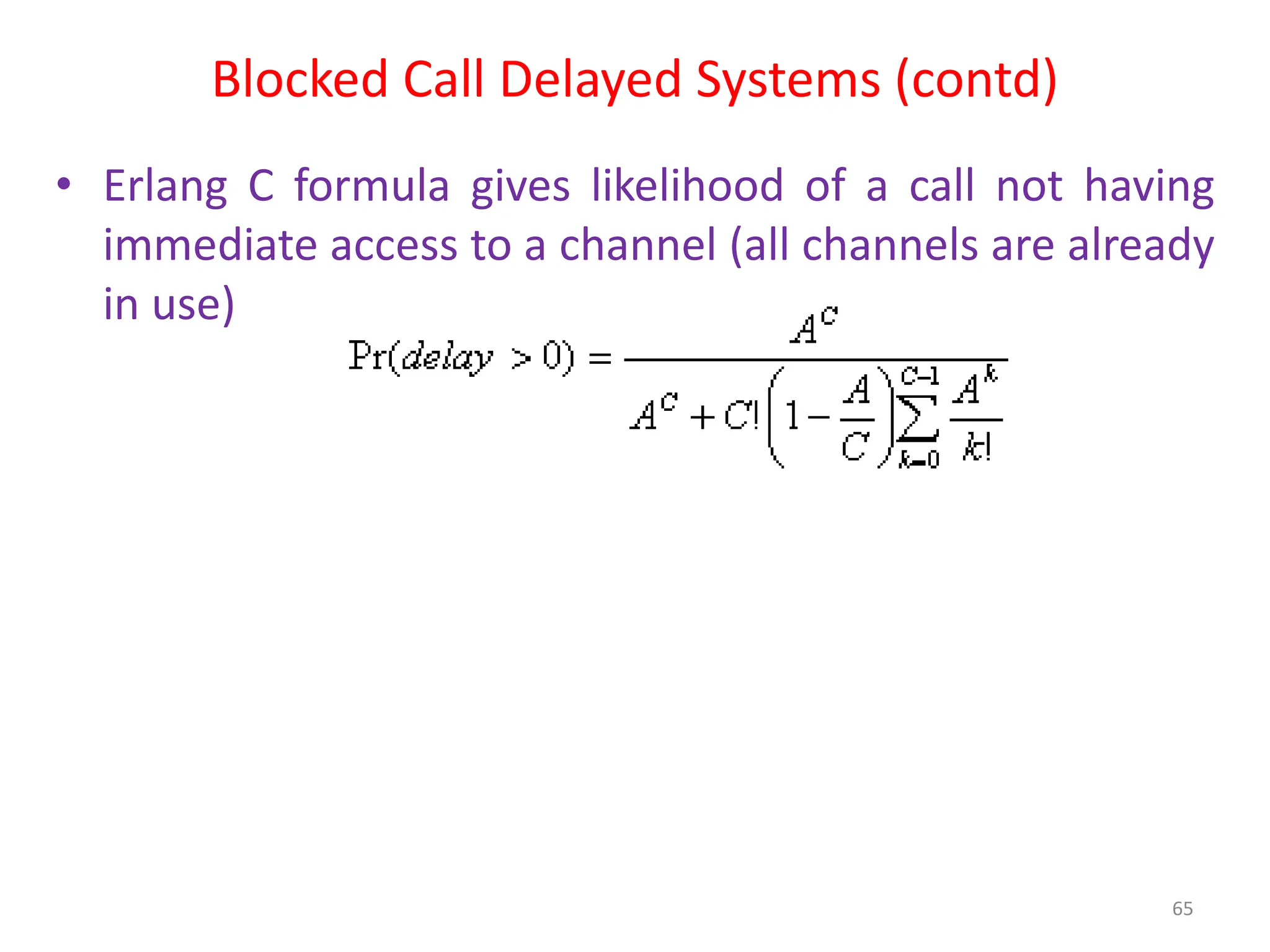
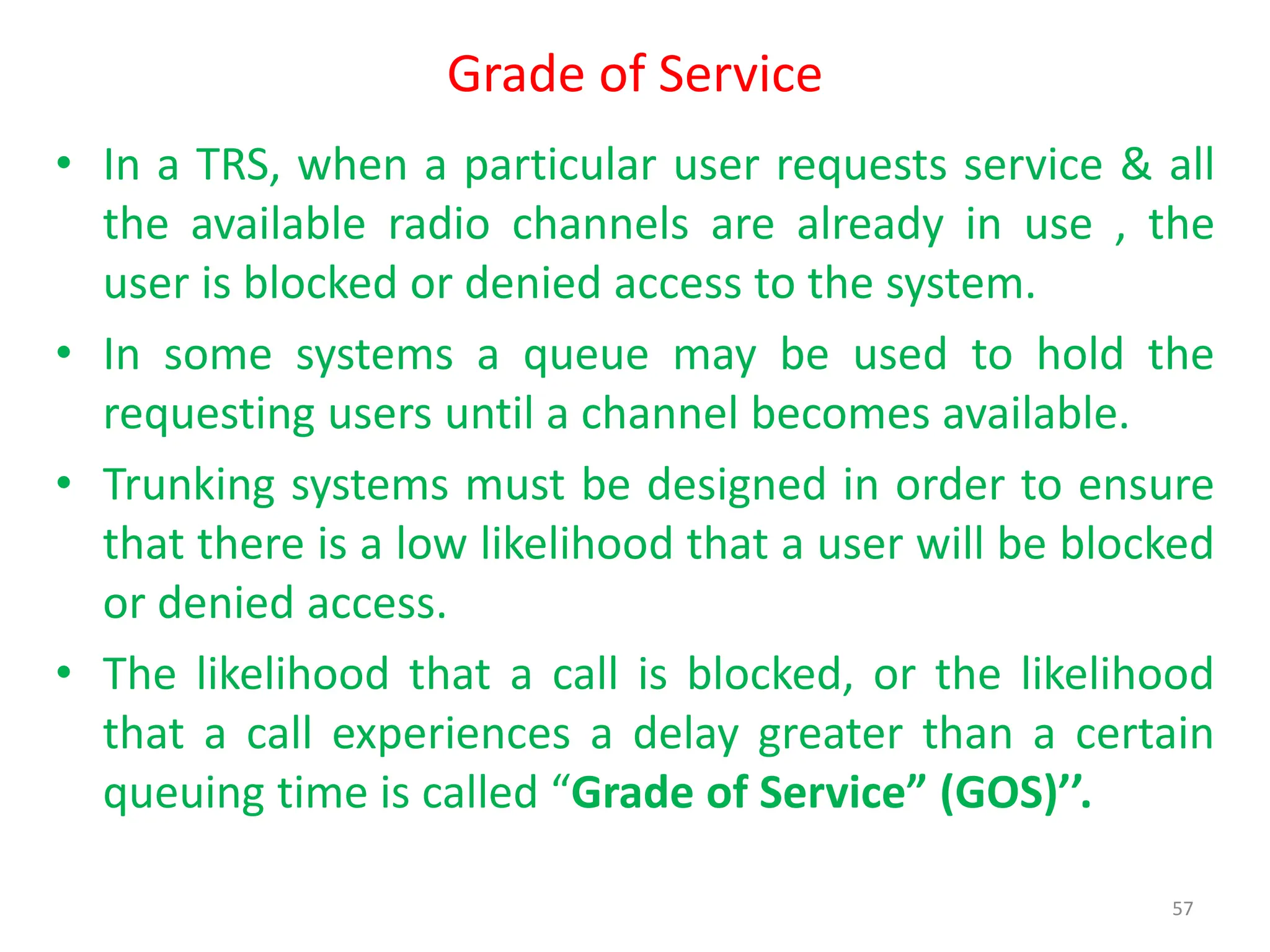
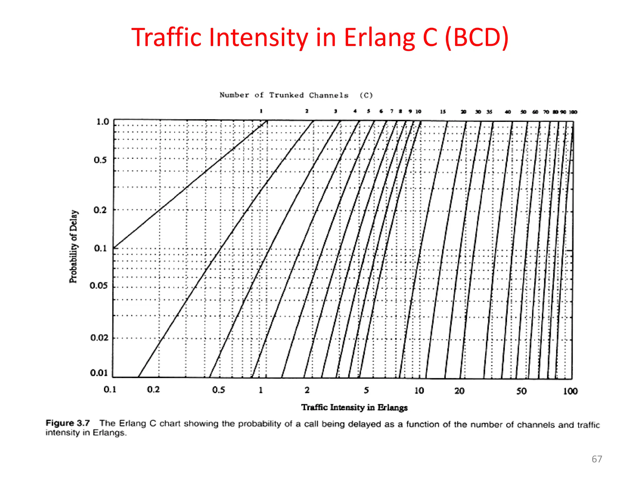
![Modeling of BCD Systems
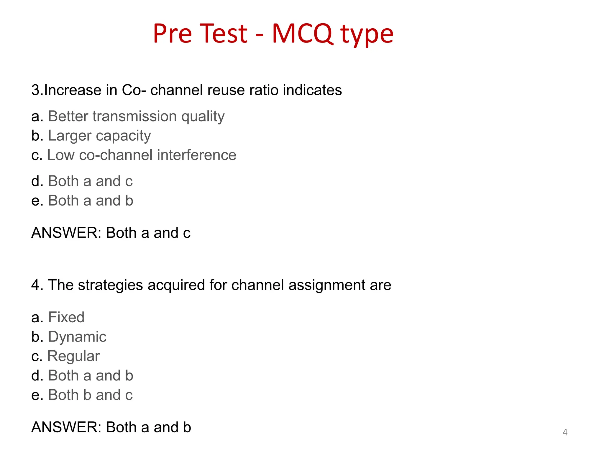
• Probability that any caller is delayed in queue for a wait time
greater than t seconds is given as GOS of a BCD System
• The probability of a call getting delayed for any period of time
greater than zero is -
P[delayed call is forced to wait > t sec]=P[delayed] x Conditional
P[delay is >t sec]
• Mathematically;
Pr [delay>t] = Pr [delay>0] Pr [delay>t | delay>0]
• Where P[delay>t | delay>0]= e(-(C-A)t/H)
Pr[delay>t] = Pr [delay>0] e(-(C-A)t/H)
– where C = total number of channels, t = delay time of
interest, H = average duration of call
66](https://image.slidesharecdn.com/mobilecommunication-240714081448-6a931d75/75/MobileCommunication-related-document-pdf-66-2048.jpg)


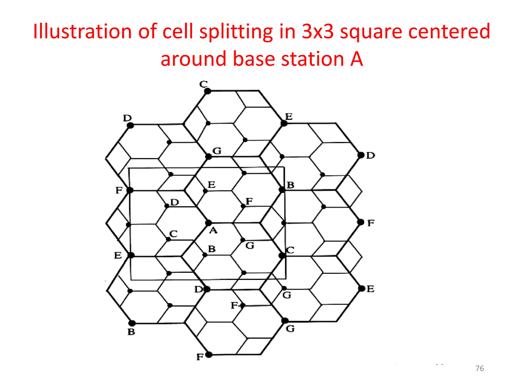
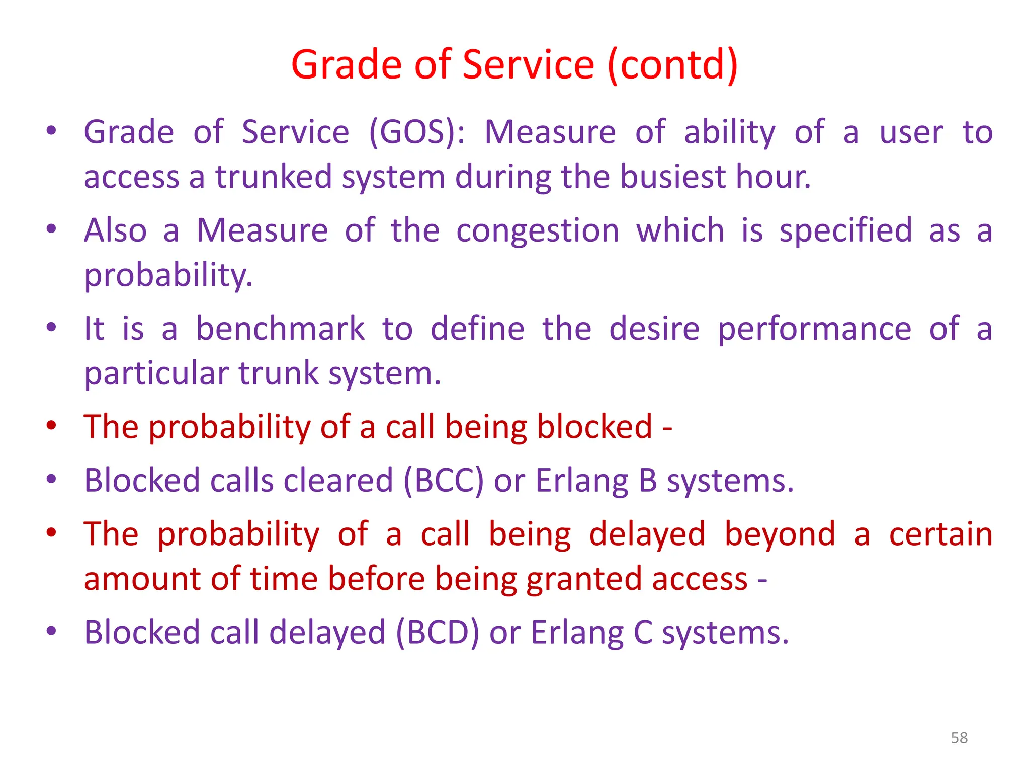
![Cell Splitting-Power Issues
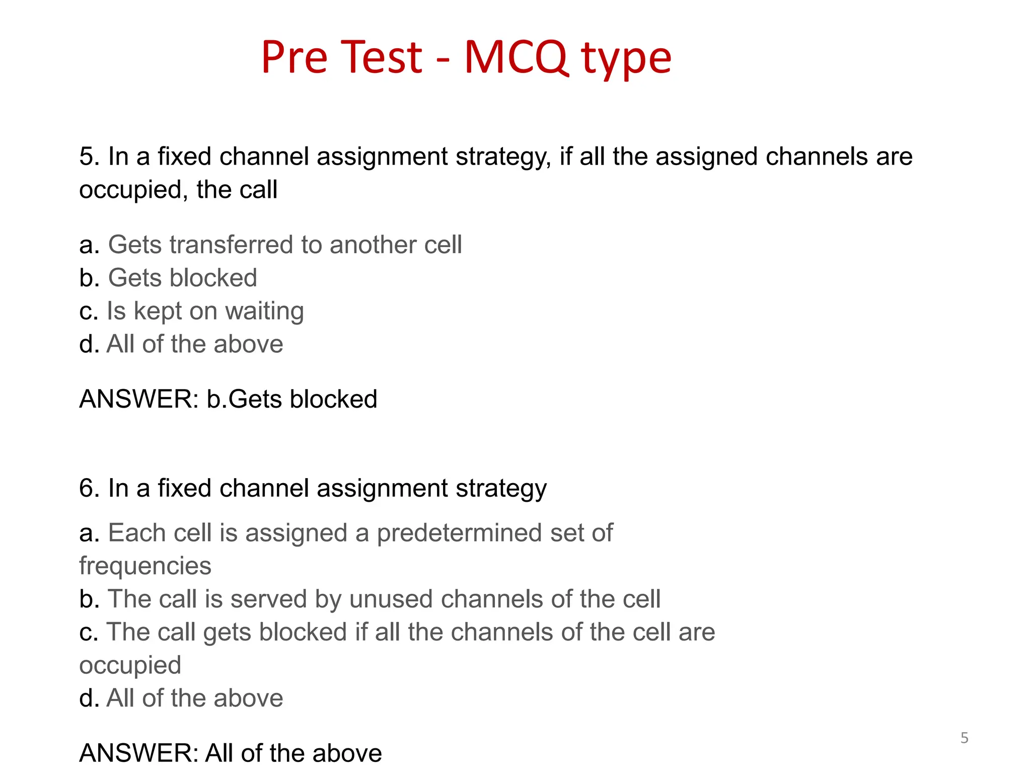
• Suppose the cell radius of new cells is reduced by half
• What is the required transmit power for these new cells?
Pr [at old cell boundary] = Pt1 (R)-n
Pr [at new cell boundary] = Pt2 (R/2)–n
• where Pt1 and Pt2 are the transmit powers of the larger and
smaller cell base stations & n is the path loss exponent.
• So, Pt2 = Pt1 / 2n
• If we take n=3 and the received powers equal to each other, then
Pt2 = Pt1 / 8
• In other words, the transmit power must be reduced by 9dB in
order to fill in the original coverage area while maintaining the
S/I requirement.
75](https://image.slidesharecdn.com/mobilecommunication-240714081448-6a931d75/75/MobileCommunication-related-document-pdf-75-2048.jpg)