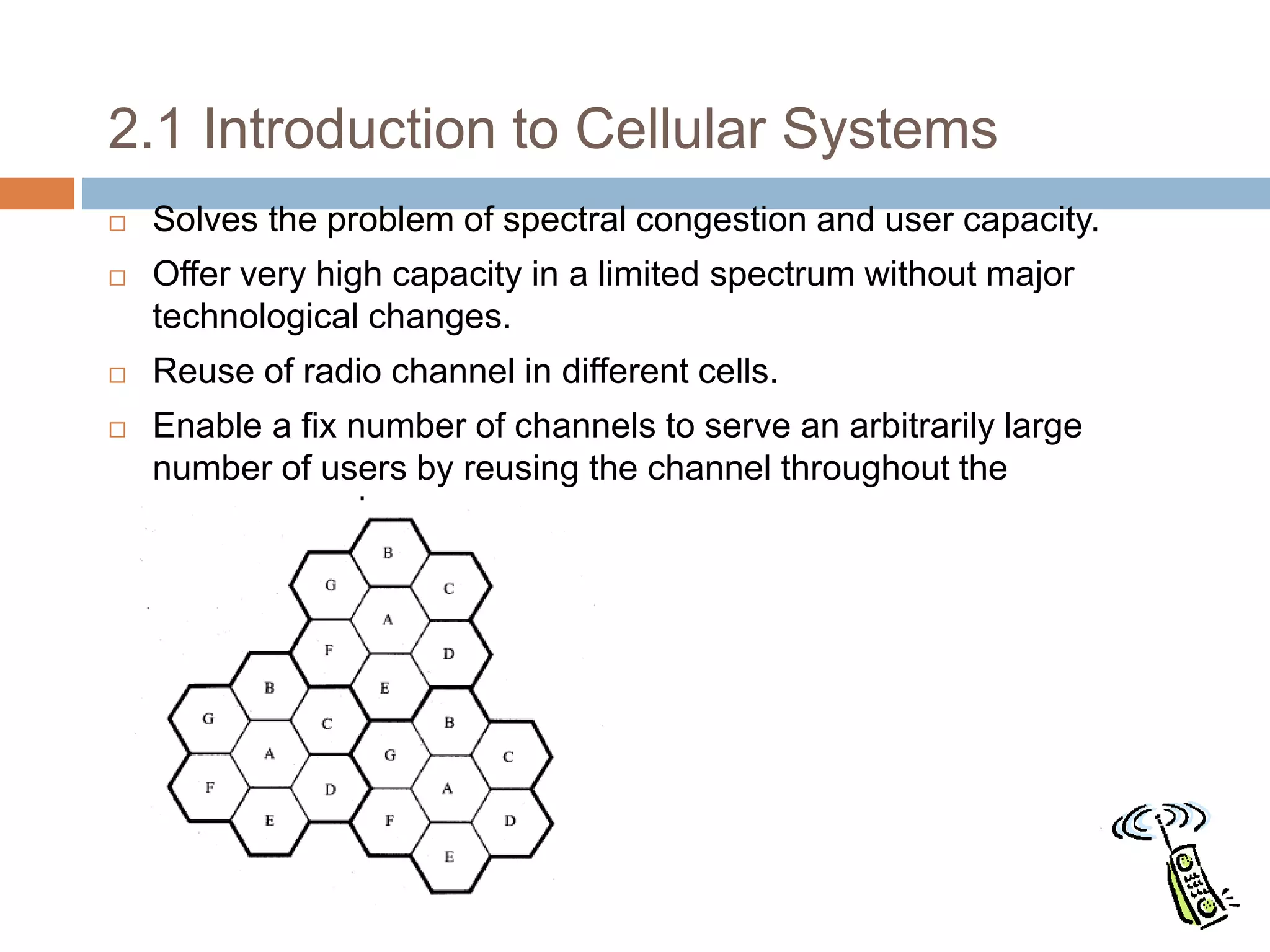
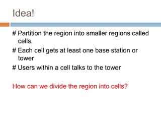
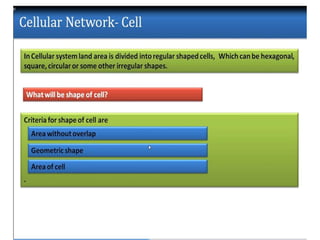
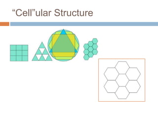
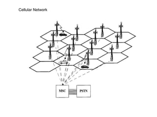
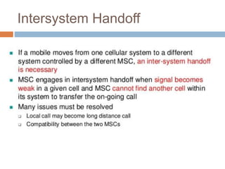
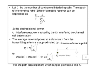
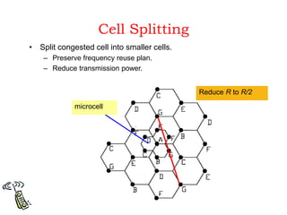
1) Cellular networks divide a region into smaller areas called cells to improve capacity and reuse frequencies. Each cell contains a base station that can communicate with user equipment within its coverage area.
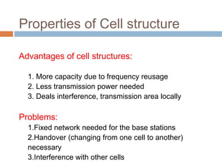
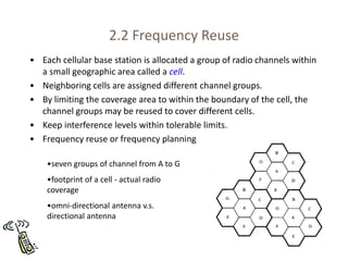
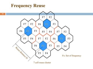
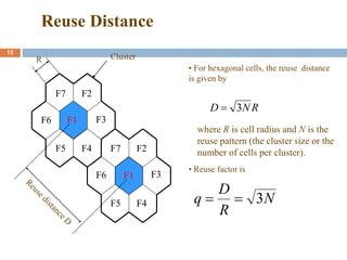
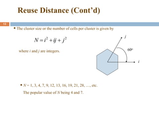
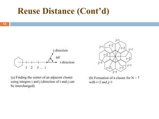
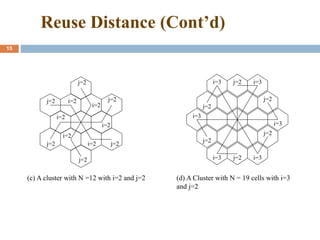
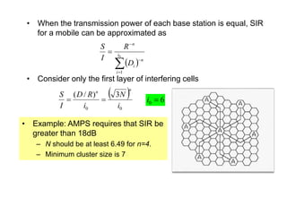
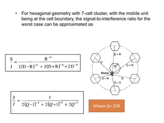
2) Frequency reuse allows the same set of frequencies to be reused in different cells by ensuring sufficient distance between cells using the same frequencies. This increases overall network capacity.
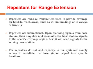
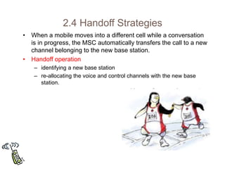
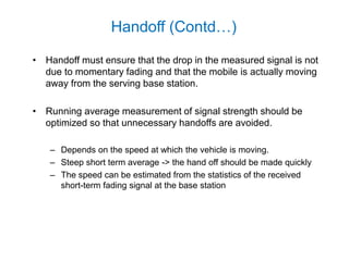
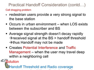
3) Handoff allows calls to be transferred between base stations as users move between cells to maintain call quality. Various handoff strategies aim to minimize call drops during handoffs.

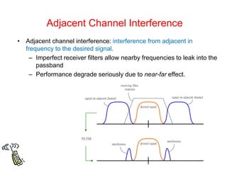
![Types of protocols [Handoff
Methods]
4 types of handoff protocols which help in
providing continuous and QOS-guaranteed
service.
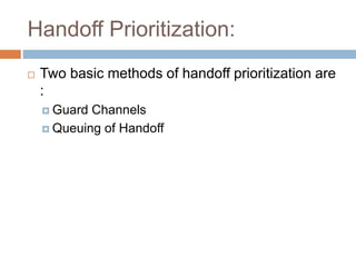
Network-controlled handoff (NCHO)
Mobile-assisted handoff (MAHO)
Soft handoff (SHO) and
Mobile-controlled handoff (MCHO)](https://image.slidesharecdn.com/wcpptunit-ii-230823020352-dd53119c/85/WC-PPT-UNIT-II-ppt-27-320.jpg)
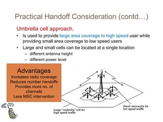
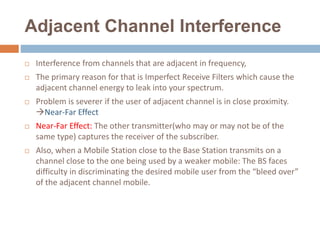
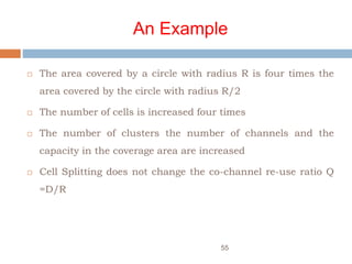
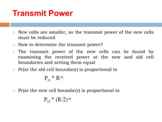
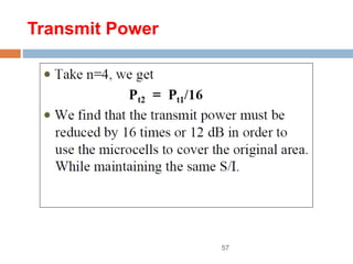
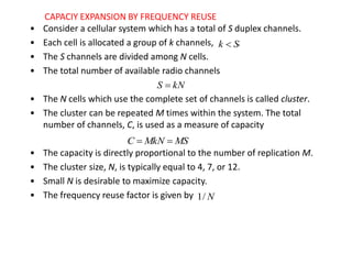
![• Transmission power reduction from to
• Examining the receiving power at the new and old cell boundary
• If we take n = 4 and set the received power equal to each other
• The transmit power must be reduced by 12 dB in order to fill in
the original coverage area.
• Problem: if only part of the cells are splited
– Different cell sizes will exist simultaneously
• Handoff issues - high speed and low speed traffic can be
simultaneously accommodated
1
t
P 2
t
P
n
t
r R
P
P
1
]
boundary
cell
old
at
[
n
t
r R
P
P
)
2
/
(
]
boundary
cell
new
at
[ 2
16
1
2
t
t
P
P ](https://image.slidesharecdn.com/wcpptunit-ii-230823020352-dd53119c/85/WC-PPT-UNIT-II-ppt-60-320.jpg)