Downloaded 114 times


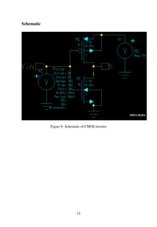


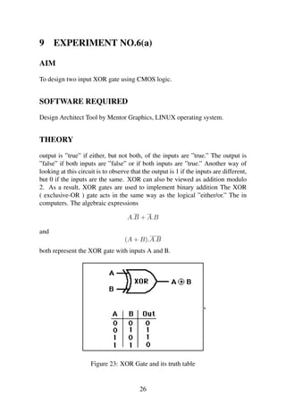


The document is a lab report submitted by Priya Hada to Mr. Venkatrao Selamneni describing 9 experiments conducted on VLSI circuits. It includes introductions to VLSI, NMOS transistors, PMOS transistors and various digital logic gates. The experiments analyze the characteristics of NMOS and PMOS transistors and implement basic logic gates like inverters, NOR gates, NAND gates and flip-flops using CMOS technology. Schematics, truth tables and output waveforms are provided for each circuit designed and analyzed in the experiments.