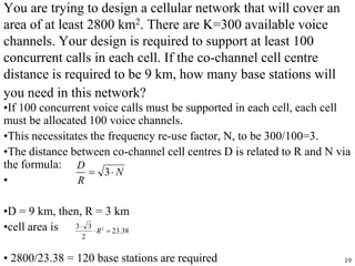
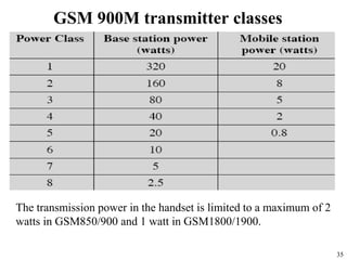
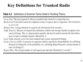
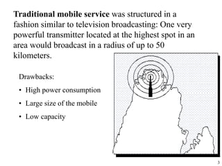
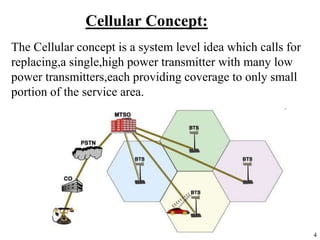
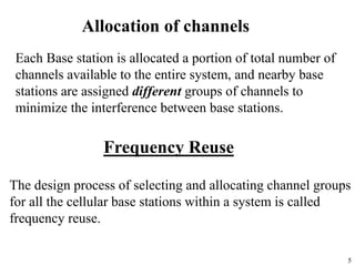
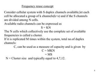
Cellular systems use multiple low-power transmitters (base stations) rather than a single, high-power transmitter to increase capacity and coverage. Frequency reuse is used to allocate channels to nearby base stations to minimize interference. Handoff strategies are employed to transfer calls between base stations as users move. Interference and power control techniques aim to equalize signal power levels and improve capacity. Traffic engineering principles including Erlang formulas are applied to determine the optimal number of channels needed based on expected call volumes.
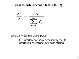
Frequencies management,Channel assignments,
Frequency reuse, System capacity and its improvement: Cell spliting and sectoring, Handoffs & its types, prioritizing handoff, Umbrella cell approach, Cell dragging, Roaming, Co channel and adjacent channel interference, Improving coverage- Repeaters for range extension and microcell zone concept, Examples
Cellular Concepts by Mian Shehzad Iqbal,
Earlier systems used single high power
transmitter. So no frequency reuse
• Cellular concept solve the problem of spectral
congestion and user capacity without any major
technological changes.
• Replaces single high power transmitter with
many low power transmitters.
• Each base station is allocated portion of
available channels.
• Distribution to neighbors so that minimize
interference.
Hexagonal shape is only logical shape.
Actual coverage of cell is known as
footprint and is determined by
measurements and prediction models.
Cell must be designed to serve the
weakest mobile at edge in footprint.
MSC plays major role by monitoring reuse
distance, cost function and other issues. • MSC
needs to collect real time data on channel
occupancy, traffic distribution and radio signal
strength indications (RSSI) this increases the
storage and computational load but provides the
advantage of increased channel utilization and
decreased probability of blocked calls.
Using recycled concrete aggregates (RCA) for pavements is crucial to achieving sustainability. Implementing RCA for new pavement can minimize carbon footprint, conserve natural resources, reduce harmful emissions, and lower life cycle costs. Compared to natural aggregate (NA), RCA pavement has fewer comprehensive studies and sustainability assessments.
ACEP Magazine edition 4th launched on 05.06.2024Rahul
This document provides information about the third edition of the magazine "Sthapatya" published by the Association of Civil Engineers (Practicing) Aurangabad. It includes messages from current and past presidents of ACEP, memories and photos from past ACEP events, information on life time achievement awards given by ACEP, and a technical article on concrete maintenance, repairs and strengthening. The document highlights activities of ACEP and provides a technical educational article for members.
Online aptitude test management system project report.pdfKamal Acharya
The purpose of on-line aptitude test system is to take online test in an efficient manner and no time wasting for checking the paper. The main objective of on-line aptitude test system is to efficiently evaluate the candidate thoroughly through a fully automated system that not only saves lot of time but also gives fast results. For students they give papers according to their convenience and time and there is no need of using extra thing like paper, pen etc. This can be used in educational institutions as well as in corporate world. Can be used anywhere any time as it is a web based application (user Location doesn’t matter). No restriction that examiner has to be present when the candidate takes the test.
Every time when lecturers/professors need to conduct examinations they have to sit down think about the questions and then create a whole new set of questions for each and every exam. In some cases the professor may want to give an open book online exam that is the student can take the exam any time anywhere, but the student might have to answer the questions in a limited time period. The professor may want to change the sequence of questions for every student. The problem that a student has is whenever a date for the exam is declared the student has to take it and there is no way he can take it at some other time. This project will create an interface for the examiner to create and store questions in a repository. It will also create an interface for the student to take examinations at his convenience and the questions and/or exams may be timed. Thereby creating an application which can be used by examiners and examinee’s simultaneously.
Examination System is very useful for Teachers/Professors. As in the teaching profession, you are responsible for writing question papers. In the conventional method, you write the question paper on paper, keep question papers separate from answers and all this information you have to keep in a locker to avoid unauthorized access. Using the Examination System you can create a question paper and everything will be written to a single exam file in encrypted format. You can set the General and Administrator password to avoid unauthorized access to your question paper. Every time you start the examination, the program shuffles all the questions and selects them randomly from the database, which reduces the chances of memorizing the questions.
Hierarchical Digital Twin of a Naval Power SystemKerry Sado
A hierarchical digital twin of a Naval DC power system has been developed and experimentally verified. Similar to other state-of-the-art digital twins, this technology creates a digital replica of the physical system executed in real-time or faster, which can modify hardware controls. However, its advantage stems from distributing computational efforts by utilizing a hierarchical structure composed of lower-level digital twin blocks and a higher-level system digital twin. Each digital twin block is associated with a physical subsystem of the hardware and communicates with a singular system digital twin, which creates a system-level response. By extracting information from each level of the hierarchy, power system controls of the hardware were reconfigured autonomously. This hierarchical digital twin development offers several advantages over other digital twins, particularly in the field of naval power systems. The hierarchical structure allows for greater computational efficiency and scalability while the ability to autonomously reconfigure hardware controls offers increased flexibility and responsiveness. The hierarchical decomposition and models utilized were well aligned with the physical twin, as indicated by the maximum deviations between the developed digital twin hierarchy and the hardware.
NUMERICAL SIMULATIONS OF HEAT AND MASS TRANSFER IN CONDENSING HEAT EXCHANGERS...ssuser7dcef0
Power plants release a large amount of water vapor into the
atmosphere through the stack. The flue gas can be a potential
source for obtaining much needed cooling water for a power
plant. If a power plant could recover and reuse a portion of this
moisture, it could reduce its total cooling water intake
requirement. One of the most practical way to recover water
from flue gas is to use a condensing heat exchanger. The power
plant could also recover latent heat due to condensation as well
as sensible heat due to lowering the flue gas exit temperature.
Additionally, harmful acids released from the stack can be
reduced in a condensing heat exchanger by acid condensation. reduced in a condensing heat exchanger by acid condensation.
Condensation of vapors in flue gas is a complicated
phenomenon since heat and mass transfer of water vapor and
various acids simultaneously occur in the presence of noncondensable
gases such as nitrogen and oxygen. Design of a
condenser depends on the knowledge and understanding of the
heat and mass transfer processes. A computer program for
numerical simulations of water (H2O) and sulfuric acid (H2SO4)
condensation in a flue gas condensing heat exchanger was
developed using MATLAB. Governing equations based on
mass and energy balances for the system were derived to
predict variables such as flue gas exit temperature, cooling
water outlet temperature, mole fraction and condensation rates
of water and sulfuric acid vapors. The equations were solved
using an iterative solution technique with calculations of heat
and mass transfer coefficients and physical properties.
Literature Review Basics and Understanding Reference Management.pptxDr Ramhari Poudyal
Three-day training on academic research focuses on analytical tools at United Technical College, supported by the University Grant Commission, Nepal. 24-26 May 2024
Harnessing WebAssembly for Real-time Stateless Streaming PipelinesChristina Lin
Traditionally, dealing with real-time data pipelines has involved significant overhead, even for straightforward tasks like data transformation or masking. However, in this talk, we’ll venture into the dynamic realm of WebAssembly (WASM) and discover how it can revolutionize the creation of stateless streaming pipelines within a Kafka (Redpanda) broker. These pipelines are adept at managing low-latency, high-data-volume scenarios.
NO1 Uk best vashikaran specialist in delhi vashikaran baba near me online vas...Amil Baba Dawood bangali
Contact with Dawood Bhai Just call on +92322-6382012 and we'll help you. We'll solve all your problems within 12 to 24 hours and with 101% guarantee and with astrology systematic. If you want to take any personal or professional advice then also you can call us on +92322-6382012 , ONLINE LOVE PROBLEM & Other all types of Daily Life Problem's.Then CALL or WHATSAPP us on +92322-6382012 and Get all these problems solutions here by Amil Baba DAWOOD BANGALI
#vashikaranspecialist #astrologer #palmistry #amliyaat #taweez #manpasandshadi #horoscope #spiritual #lovelife #lovespell #marriagespell#aamilbabainpakistan #amilbabainkarachi #powerfullblackmagicspell #kalajadumantarspecialist #realamilbaba #AmilbabainPakistan #astrologerincanada #astrologerindubai #lovespellsmaster #kalajaduspecialist #lovespellsthatwork #aamilbabainlahore#blackmagicformarriage #aamilbaba #kalajadu #kalailam #taweez #wazifaexpert #jadumantar #vashikaranspecialist #astrologer #palmistry #amliyaat #taweez #manpasandshadi #horoscope #spiritual #lovelife #lovespell #marriagespell#aamilbabainpakistan #amilbabainkarachi #powerfullblackmagicspell #kalajadumantarspecialist #realamilbaba #AmilbabainPakistan #astrologerincanada #astrologerindubai #lovespellsmaster #kalajaduspecialist #lovespellsthatwork #aamilbabainlahore #blackmagicforlove #blackmagicformarriage #aamilbaba #kalajadu #kalailam #taweez #wazifaexpert #jadumantar #vashikaranspecialist #astrologer #palmistry #amliyaat #taweez #manpasandshadi #horoscope #spiritual #lovelife #lovespell #marriagespell#aamilbabainpakistan #amilbabainkarachi #powerfullblackmagicspell #kalajadumantarspecialist #realamilbaba #AmilbabainPakistan #astrologerincanada #astrologerindubai #lovespellsmaster #kalajaduspecialist #lovespellsthatwork #aamilbabainlahore #Amilbabainuk #amilbabainspain #amilbabaindubai #Amilbabainnorway #amilbabainkrachi #amilbabainlahore #amilbabaingujranwalan #amilbabainislamabad
2. 2
Topics
• Cellular Concept
• Frequency reuse
• Channel Assignment Strategies
• Handoff Strategies
• Interference and System Capacity
• Co-channel Interference
• Adjacent Channel Interference
• Power Control for Reducing Interference
• Trunking
• Improving Capacity in Cellular Systems
3. 3
Traditional mobile service was structured in a
fashion similar to television broadcasting: One very
powerful transmitter located at the highest spot in an
area would broadcast in a radius of up to 50
kilometers.
Drawbacks:
• High power consumption
• Large size of the mobile
• Low capacity
4. 4
Cellular Concept:
The Cellular concept is a system level idea which calls for
replacing,a single,high power transmitter with many low
power transmitters,each providing coverage to only small
portion of the service area.
5. 5
Allocation of channels
Each Base station is allocated a portion of total number of
channels available to the entire system, and nearby base
stations are assigned different groups of channels to
minimize the interference between base stations.
Frequency Reuse
The design process of selecting and allocating channel groups
for all the cellular base stations within a system is called
frequency reuse.
8. 8
Frequency reuse concept
Consider cellular system with S duplex channels available,let each
cell be allocated a group of k channels(k<s) and if the S channels
are divided among N cells.
Available radio channels can be expressed as
S = KN
The N cells which collectively use the complete set of available
frequencies is called a cluster.
If it is replicated M times within the system, total no.of duplex
channels:
C, can be used as a measure of capacity and is given by
C = MKN
= MS
N = Cluster size and typically equal to 4,7,12.
9. 9
From geometry of hexagons is such that the number of cells per
Cluster, N, can only have the values which satisfy equation
N = i2 + ij + j2
i and j are non-negative integers.
N can have the values of 3, 4, 7, 9, 12, 13,19,…
11. 11
Channel assignment strategies
Fixed channel assignment
Each cell is allocated a predetermined set of voice channels. Any
call attempt within the cells can only be served by unused channels
in that particular cell. If all the channels in the cell are occupied,
the call is blocked and the subscriber does not receive service.
Fixed assignment with borrowing
Before a call is blocked, a BS might try to “borrow" a channel
from a neighbouring BS.
Dynamic channel assignment
The voice channels are not allocated to different cells permanently,
instead each time a call request is made, the serving base station
request a channel from the mobile switching center.
12. 12
Handoff strategies
•When a mobile moves into a different cell while a
conversation is in progress, the MSC automatically
transfers the call to a new channel belonging to the new
base station.
This handoff operation not only involves identifying a
new base station, but also requires that the voice and
control signals be allocated to channels associated with
the new base station.
14. 14
•In the first generation analog cellular systems, Signal
strength Measurements are made by the base station to
determine the relative location of each mobile user with
respect to the base station.
•In second generation systems that use digital TDMA
technology,handoff decisions are made mobile assisted
handoff (MAHO). Every mobile station measures the
received power from surrounding base stations and
continually reports the results of these measurements to the
serving base station. A handoff is initiated when the power
received from the base station of a neighboring cell begins
to exceed the power received from the current base station
by a certain level or for a certain period of time.
15. 15
Prioritizing handoffs
• Guard channel concept
In this a fraction of total available channels in a cell is
reserved exclusively for handoff requests from
ongoing calls which may be handed off into the cell.
• Queuing of handoff requests is another method
to decrease the probability of forced termination of a
call due to lack of available channels.
16. 16
Practical handoff considerations
•Using different antenna heights and different power levels it is possible
to provide large and small cells which are co-located at a single location.
This technique is called umbrella cell approach and is used to provide
large area coverage to high speed users while providing small area
coverage to users traveling at low speeds.
The umbrella cell approach ensures that the number of handoffs in
minimized for high speed users and provides additional microcell
channels for pedestrian users.
17. 17
Hard handoff and soft handoff
• Hard handoff: When the signal strength of a neighboring
cell exceeds that of the current cell, plus a threshold, the
mobile station is instructed to switch to a new frequency
band that is within the allocation of the new cell.
• Soft handoff: a mobile station is temporarily connected to
more than one base station simultaneously. A mobile unit
may start out assigned to a single cell. If the unit enters a
region in which the transmissions from two base stations are
comparable (within some threshold of each other), the
mobile unit enters the soft handoff state in which it is
connected to the two base stations. The mobile unit remains
in this state until one base station clearly predominates, at
which time it is assigned exclusively to that cell.
18. 18
Co-channel reuse ratio
Assuming same cell size and that the base stations
transmit the same power
The Co-channel interference ratio becomes
independent of the Transmitted power and becomes
function of Radius of the cell (R) and Distance
between centers of the nearest co-channel cells (D)
19. 19
You are trying to design a cellular network that will cover an
area of at least 2800 km2. There are K=300 available voice
channels. Your design is required to support at least 100
concurrent calls in each cell. If the co-channel cell centre
distance is required to be 9 km, how many base stations will
you need in this network?
•If 100 concurrent voice calls must be supported in each cell, each cell
must be allocated 100 voice channels.
•This necessitates the frequency re-use factor, N, to be 300/100=3.
•The distance between co-channel cell centres D is related to R and N via
the formula:
•
•D = 9 km, then, R = 3 km
•cell area is
• 2800/23.38 = 120 base stations are required
N
R
D
3
38
.
23
2
3
3 2
R
20. 20
Interference
• Interference is a major limiting factor in the performance of
cellular radio system
• Sources of Interference
• Another mobile in the same cell
• A call in progress in a neighboring cell
• Other base stations operating in the same
frequency band or
• Any non cellular system which inadvertently leaks
energy into the cellular frequency band
The two major types of system generated interferences are
Co-channel interference
Adjacent channel interference
23. 23
Signal to Interference Ratio (SIR)
where S – desired signal power
Ii – Interference power caused by the ith
interfering co-channel cell base station
0
1
i
i
i
I
S
I
S
24. 24
Assuming that the transmitting power of each base
station is equal and the path loss exponent same
through out the coverage area
0
1
)
(
i
i
n
i
n
D
R
I
S
io – The number of Co-channel interfering cells and
S/I – Signal to interference ratio at the desired
mobile receiver
25. 25
Considering first layer of interfering cells. If all the
interfering base stations are equidistant from the
desired base station (by D between cell centers)
0
0
)
3
(
)
/
(
i
N
i
R
D
I
S n
n
26. 26
For the case where the mobile unit is at the cell
boundary in a 7-cell cluster (the worst case). The distances from
the co-channel interfering cells are approximated to
D-R, D and D+R .
Assuming n= 4
4
4
4
4
2
)
(
2
)
(
2
D
R
D
R
D
R
I
S
4
4
4
2
)
1
(
2
)
1
(
2
1
Q
Q
Q
I
S
the worst case SIR
27. 27
For N=7 , Q= 4.58 from
From
(worst case)
S/I = 49.56 (17 dB)
But by using
S/I = 17.8 dB
(average)
Hence for a 7-cell cluster, the S/I ratio is slightly less that 18 dB
in the worst case.
4
4
4
2
)
1
(
2
)
1
(
2
1
Q
Q
Q
I
S
0
1
)
(
i
i
n
i
n
D
R
I
S
28. 28
Adjacent Channel Interference
1. What is adjacent channel interference?
Interference resulting from signals which are adjacent
in frequency to desired signal.
2. Why does it occur?
This results from imperfect receiver filters which allow
nearby frequencies to leak into the pass band.
3. How can adjacent channel interference be reduced?
careful filtering and channel assignment
By keeping the frequency separation between each
channel in a given cell as large as possible
By sequentially assigning successive channels in the
frequency band to different cells
29. 29
Power Control For Reducing Interference
In practical cellular radio and personal communication systems
the power levels transmitted by every subscriber unit are
controlled by the serving base stations
Need for Power Control:
• Received power must be sufficiently above the background
noise for effective communication
• Desirable to minimize power in the transmitted signal from
the mobile. Reduce co-channel interference, alleviate health
concerns, save battery power
• In Spread Spectrum systems using CDMA, it’s desirable to
equalize the received power level from all mobile units at the
Base station.
31. 31
•Power control enable the transmitter side to
adapt its output power according to pilot signal’s
strength.
•Aims to solve the ‘near-far’ problem with the
goal to achieve uniform signal to interference
ratio (SIR) for all the active users.
•Two methods:
a) open-loop Power Control
b) closed-loop Power Control.
Power Control
32. 32
Open-loop Power Control
• In open-loop PC, the mobile measures the pilot
strength (continuously transmitted by the BS) which
is related to path loss. If the pilot gets weak it
powers-up, when the pilot gets strong it powers
down.
• It assumes that the forward and reverse link are
similar.--- not accurately (incase of FDD).
• Quickly react. – e.g. mobile emerges from a behind a
large building.
• It gives quite results with the TDD mode.
• It is used in WCDMA-FDD mode but only to
provide initial power setting of the mobile station at
the beginning of the connection.
33. 33
Closed-loop Power Control
• In closed-loop PC, feedback is used whereby the
base-station measures the signal-quality of mobile;
e.g. frame error rate (FER) and commands each
mobile to power up and down accordingly in order to
keep the overall FER at desired level. – reverse link.
• The mobile provides information about received
signal quality to the BS, which then adjusts
transmitted power. – forward link.
• The UTRA-FDD mode uses fast closed-loop power
control technique both in uplink and downlink.
35. 35
GSM 900M transmitter classes
The transmission power in the handset is limited to a maximum of 2
watts in GSM850/900 and 1 watt in GSM1800/1900.
36. 36
Equivalent isotropically
radiated power (dBW)
Network Frequency Base
Stations
Minimu
m
Averag
e
Maxim
um
Vodafone 900 MHz 23 7.1 7.1 7.4
O2 900 MHz 21 0.3 7.3 11.7
Orange 1800 MHz 22 12.9 15.2 19.4
T-Mobile 1800 MHz 25 4.0 9.3 11.0
T-Mobile 2100 MHz 3 9.0 10.0 11.0
Low-height high-power mobile phone base station (under 10m)
7 dBW represents 5 watts radiated power per channel. 15 dBW (the
Orange average) represents 32 watts radiated power per channel
37. 37
Traffic Engineering
Developed in PSTN, but equally apply to cellular
networks.
Ideally, Num of channels = Num of total subscribers (could
be active at any time).
It is not practicable to have the capacity to handle any
possible load at all time. And not all subscribes place calls
at the same time.---- share the channels.
39. 39
1 Erlang :
Represents the amount of traffic intensity carried by a channel that is
completely occupied : 1 call hour per hour
Ex: a radio channel that is occupied for 30 min during an hour
carries 0.5 Erlangs of traffic.
Grade of Service :
• Measure of the ability of a user to access a trunked system during
the busiest hour.
• The busy hour is based on customer demand at the busiest hour
during a week, month or year.
• For cellular radio systems : rush hour is between 4pm-6pm,
Thurs-Fri.
40. 40
Traffic intensity generated by each user : Au Erlangs
Au = H
H : average duration of the call
: average number of call requests per unit time
For a system containing U users and unspecified number of channels,
Total offered traffic intensity : A Erlangs
A = U Au
In C channel trunked system, if the traffic is equally distributed among
the channels,
Traffic intensity per channel : Ac Erlangs
Ac = U Au/ C
Formulas and derivation
41. 41
Types of trunked system
• No queuing for call requests
“ Blocked Calls Cleared ”
• Queue is provided to hold calls
“ Blocked Calls Delayed ”
Assumption :
• calls arrive as determined by Poisson distribution
• infinite number of users
• memoryless arrivals of requests : all users can request channel at
any time
• probability of user occupying a channel is exponentially
distributed
• finite number of channels available in the trunking pool
42. 42
Erlang B formula : determines the probability that the call is
blocked, and is the measure of the GOS for a trunked system that
provides no queuing for blocked calls.
Erlang C formula : if offered call cannot be assigned a channel, it
is placed in a queue which has a finite length, each call is then
serviced in the order of its arrival.
Probability that an arriving call occurs when all C channels are
busy and thus has to wait is
43. 43
If no channels are immediately available the call is delayed, and the
probability that the delayed call is forced to wait more than ‘t’ secs is
Trunking efficiency :
Measure of the number of users which can be offered a particular
GOS with a particular configuration of fixed channels.
Allocation of channels in a trunked radio system has a major
impact on overall system capacity.
47. 47
Improve Capacity
• Cell Splitting : It allows an orderly growth of the
cellular system
• Sectoring : It uses Directional antennas to control the
interference and frequency reuse of channels.
• Zone Microcell: It distributes the coverage of the
Cell.
• More bandwidth
• Borrow channel from nearby cells
48. 48
CELL SPLITTING
• Cell Splitting : It is the process of subdividing the congested
cell into smaller cells.
• Each of the smaller cells will have their own base station with
a reduction in antenna height and transmitted power.
• The smaller cells are known as Microcells.
• Cell Splitting increases the capacity of the cellular system as it
increases the number of times the channels are reused
• The increased number of cells would increase the number of
clusters over the coverage region,which in turn increase the
number of channels,and thus capacity in the coverage area
• Cell Splitting allows the system to grow by replacing large
cells with smaller cells without changing the co-channel re-
use ratio Q
51. 51
Sectoring:
• The co-channel interference in a cellular system can
be decreased by replacing the omni directional
antenna at the base station by several directional
antennas, each radiating within a specified sector.
• The process of reducing the co-channel interference
and thus increasing the capacity of the system by
using directional antennas is known as Sectoring.
• In general a cell is partitioned into three 120 degree
sectors or six 60 degree sectors.
• When sectoring is employed, the channels used in a
particular cell are broken down into sectored groups
and are used only in a particular sector.
55. 55
• The Improvement in (S/I) suggests that the
minimum required (S/I) of 18 dB can be easily
achieved with 7-cell reuse by employing 120
degree sector technique when compared to 12-cell
reuse
• Therefore Sectoring reduces interference and
increases the capacity by an amount of (12/7) i.e
1.714
• In general, the reduction in interference by
sectoring enables planners to reduce the cluster
size N, and provides an additional freedom in
assigning channels
56. 56
Disadvantages:
• Increased number of antennas at each base station
• Decrease in trunking efficiency due to channel
sectoring at each base station
• As sectoring reduces the coverage area of a
particular group of channels, the number of
handoffs increase.
58. 58
ADVANTAGES OVER SECTORING
• As the mobile travels from one zone to another
within the cell, it retains the same channel.Thus, a
handoff is not required at the MSC
• A given channel is active only in the particular
zone in which the mobile is traveling and hence
the base station radiation is localised and
interference is reduced
• The co-channel interference is also reduced as a
large base station is replaced by several lower
powered transmitters on the edges of the cell
59. 59
Summary
• In this chapter,concepts like handoff,frequency
reuse,trunking efficiency have been studied
• The capacity of a cellular system,it’s dependence on
several factors and the methods to increase the
capacity have also been studied
• The main objective of these points is to increase the
number of users in the system