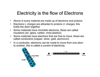
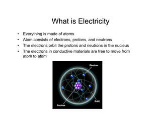
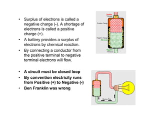
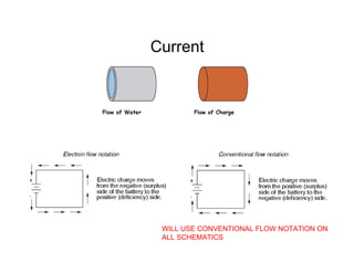
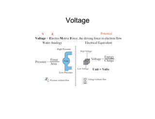
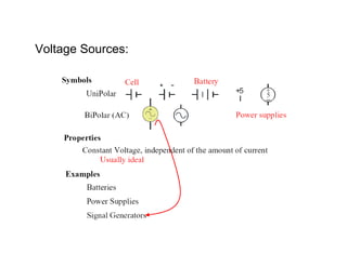
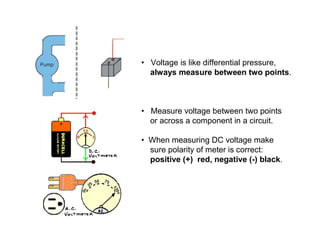
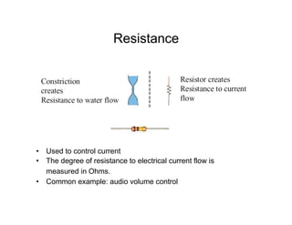
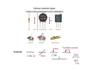
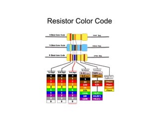
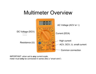
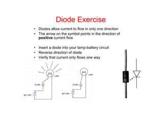
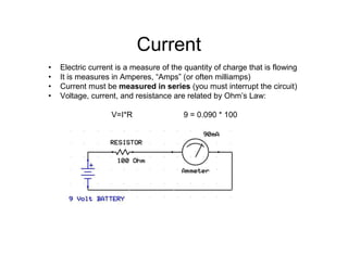
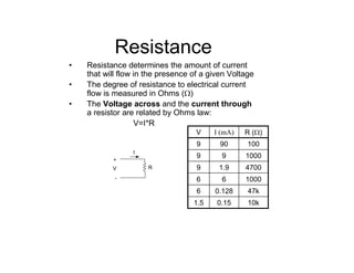
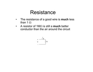
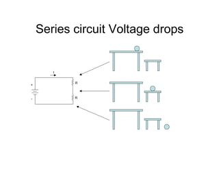
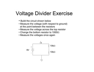
Intro to Electronics
Things to be covered:
• What is electricity
• Voltage, Current, Resistance
• LEDs
• Ohm’s Law
• Capacitors
• Breadboards
• Atoms in every material are made up of electrons and protons
• Electrons (- charge) are attracted to protons (+ charge), this
holds the atom together
• Some materials have immobile electrons, these are called
insulators (air, glass, rubber, most plastics)
• Some materials have electrons that are free to move, these are
called conductors (copper, silver, gold, aluminum)
• In a conductor, electrons can be made to move from one atom
to another, this is called a current of electricity.
Electricity is the flow of Electrons
What is Electricity
• Everything is made of atoms
• Atom consists of electrons, protons, and neutrons
• The electrons orbit the protons and neutrons in the nucleus
• The electrons in conductive materials are free to move from
atom to atom
• Surplus of electrons is called a
negative charge (-). A shortage of
electrons is called a positive
charge (+).
• A battery provides a surplus of
electrons by chemical reaction.
• By connecting a conductor from
the positive terminal to negative
terminal electrons will flow.
• A circuit must be closed loop
• By convention electricity runs
from Positive (+) to Negative (-)
• Ben Franklin was wrong
Current
WILL USE CONVENTIONAL FLOW NOTATION ON
ALL SCHEMATICS
Voltage
• A battery has a positive terminal (+) and a negative terminal (-)
• The Voltage measured between the terminals of a battery is a
measure of the ability of the battery to move charge through an
external circuit.
Water Analogy
• A battery is analogous to a pump
• A higher voltage battery is analogous to a higher pressure pump
Voltage
Voltage Sources:
• Voltage is like differential pressure,
always measure between two points.
• Measure voltage between two points
or across a component in a circuit.
• When measuring DC voltage make
sure polarity of meter is correct:
positive (+) red, negative (-) black.
Resistance
• Used to control current
• The degree of resistance to electrical current flow is
measured in Ohms.
• Common example: audio volume control
Various resistors types
Resistor Color Code
Multimeter Overview
DC Voltage (DCV)
Resistance (Ω)
Current (DCA)
AC Voltage (ACV or ~)
Common connection
High current
ACV, DCV, Ω, small current
IMPORTANT: when set to any current scale,
meter must only be connected in series (like a “smart wire”)
Multimeter Scales
microamps1/1,000,000µA
milliamps1/1000mA
Amperes (Amps)1A
megohms1,000,000MΩ
kilohms1000kΩ
Ohms1Ω
millivolts1/1000mV
Volts1V
Multimeter Notes
• IMPORTANT: when set to any current
scale, the meter must only be connected
in series (like a “smart wire”)
• When measuring current, start at a high
scale and move down
• A resistor must be removed from a circuit
before measuring its resistance
Measuring Voltage
• Always measured between two points in a circuit
• Negative (black lead) connects to a reference point
(often ground or battery -)
• Positive (red lead) connects to another point in the circuit
Make sure the meter is set to a Voltage scale
Measuring Current
• Current is measured through a section of a circuit
• Meter must be connected in series
• Open a section of the circuit
• Re-complete the circuit with the meter
• Meter acts like a “smart wire”
Make sure the meter is set to a current scale
Measuring Resistance
• Measured with resistor (or other device) out of circuit
• Connect one lead to each lead of the component
Make sure the meter is set to a resistance scale
Exercise
• Measure DC voltage from battery using multimeter
• Connect light bulb to 9 Volt battery
• Connect light bulb to 3 Volt battery
• Light should be brighter when connected to higher voltage
• Find a 50 Ohm resistor using multimeter
• Insert resistor into the circuit
• Light should be dimmer
Diode Exercise
• Diodes allow current to flow in only one direction
• The arrow on the symbol points in the direction of
positive current flow
• Insert a diode into your lamp-battery circuit
• Reverse direction of diode
• Verify that current only flows one way
• Electric current is a measure of the quantity of charge that is flowing
• It is measures in Amperes, “Amps” (or often milliamps)
• Current must be measured in series (you must interrupt the circuit)
• Voltage, current, and resistance are related by Ohm’s Law:
V=I*R 9 = 0.090 * 100
Current
Assignment
Assignment for Thursday Jan 28th:
• Order Arduino Kit ! http://www.adafruit.com/index.php?main_page=product_info&cPath=17&products_id=68
• Complete survey
• Read Physical Computing, introduction and chapters 1-3
(note info relating to specific microcontrollers and BASIC)
• Read soldering tutorial pp. 41-45 of Physical Computing.,
• Review online soldering information available at:
http://www.aaroncake.net/electronics/solder.htm
http://itp.nyu.edu/physcomp/Tutorials/SolderingAPerfBoard
There is also a rather extensive video on soldering available at:
http://blog.makezine.com/archive/2007/01/soldering_tutor_1.html
More on Voltage
• Also called “electromotive force”
• Things fall because of gravitational force
• Currents flow in a circuit because of
electromotive force (Voltage)
• Objects will only fall if they are given a path
to the ground
• Electric current will only flow if given a path
from high to low Voltage
Voltage Potential
Gravitational Potential Analogy
+
-
+
-
• a battery is like a bin of balls on the table,
constantly supplying balls of a given potential
• imagine the table under water,
air – low resistance, water - higher resistance
Voltage
• Voltage is always measured between
two points in a circuit
• Sometimes we refer to a “voltage drop”
or “voltage difference” between two
points
• Other times voltage is stated with
respect to a reference point called
“ground” (usually the negative source of
power)
• Voltage drops occur across components
• The voltage between one end of a wire
to the other is zero
Current
• Electric current (Amps) is the quantity of charge
flowing through a section of a circuit
• Voltage may be present between two points, but
current will only flow if there is a circuit between the
points
• A current meter (Ammeter) must be inserted in series
(you must interrupt the circuit)
• Think of an Ammeter as a smart wire telling you how
much current is passing through it
Current & Voltage
• Voltage is always measured between two
points in a circuit
• Sometimes we refer to a “voltage drop” or
“voltage difference” between two points or
across a component
• Current is measured at a point in a circuit
• An ammeter acts like a smart wire telling
you how much current is passing through it
+
-
V
A
Resistance
• Resistance determines the amount of current
that will flow in the presence of a given Voltage
• The degree of resistance to electrical current
flow is measured in Ohms (Ω)
• The Voltage across and the current through
a resistor are related by Ohms law:
V=I*R
+
-
V R
I
10k0.151.5
47k0.1286
100066
47001.99
100099
100909
R (Ω)I (mA)V
Resistance
+
-
V R
I
• The resistance of a good wire is much less
than 1 Ω
• A resistor of 1MΩ is still a much better
conductor than the air around the circuit
Series Circuits
• Current is conserved in a circuit
• I1 = I2 = I3
• The Voltage across each resistor depends
on its individual resistance
• The voltage across each resistor obeys
Ohms law
+
- R
I1
R
I2
I3
Series circuit Voltage drops
+
- R
R
I
Voltage Divider Exercise
• Build the circuit shown below
• Measure the voltage (with respect to ground)
at the point between the resistors
• Measure the voltage across the top resistor
• Change the bottom resistor to 1000Ω
• Measure the voltages once again
+
-
I
9V
10kΩ
10kΩ
Voltage Divider Exercise
+
-
I
9V
R2
R1
4.54.510kΩ10kΩ
.828.21kΩ10kΩ
6320kΩ10kΩ
V2V1R2R1
Potentiometer as Voltage Divider
+
-
I
9V
V
Power & Ground Symbols
Series vs Parallel Circuits
In the parallel circuit:
• Voltage across both resistors is the same
• Current divides between the two resistors
• I1 = I2 + I3
• The voltage across and current through
each resistor still obey Ohms law
+
- R
I1
R
I2
I3
+
-
I1
I2 I3
Resistors in Series
• Resistances add when wired in series
• Rtotal = R1 + R2
• Example: 1200Ω + 3000Ω = 4200Ω
Resistors in Parallel
• Resulting resistance is always less than either
• If resistors are equal, resulting resistance will be half
• Equation and example:












+
=
21
11
1
RR
Rtotal
Ω=












+
857
3000
1
1200
1
1
Light Emitting Diodes (LEDs)
• Will only pass current in one direction
• Behave like 1-3 volt light bulbs
• Generally require a resistor in series with them
• Connect LED in series with 1000 Ohm resistor
• Connect LED in series with 100 Ohm resistor
• Add variable resistor (potentiometer) to the mix
Exercises
• Use the multimeter to measure the current
through 1k and 100Ω resistors
• Build a series circuit using an LED
and a flex sensor
Prototyping Board
Example of how components are
Inserted in the protoboard
Capacitance
Battery
Capacitor
Unit = Farad
Pico Farad - pF = 10-12F
Micro Farad - uF = 10-6F
• A capacitor is used to store charge for a short amount of time
• It is like a small rechargeable battery
• Capacitance is a measure of the quantity of charge that a
capacitor can store (at a given voltage)
• Capacitance is measured in Farads (often microfarads)
Capacitor Exercise
• Charge the capacitor by connecting it to the battery
• Observe polarity
• Use the capacitor to power the LED
• Use a smaller resistor in series with the LED
Capacitors can be used for timing
Capacitor Discharge
Capacitance
• What will happen with this circuit?
• What will happen if the battery polarity is reversed?
Capacitance & AC power
• In its simplest form AC is just DC switching polarity
• A capacitor will conduct AC but not DC
Resources
Technical texts
The Art of Electronics, by Horowitz and Hill
The Radio Amateurs Handbook
Anything by Forest Mims
Organizations:
Dorkbot.org
Make Magazine and MakePhilly http://www.makephilly.com/
The Hacktory http://thehacktory.org/content/about
NextFab http://nextfabstudio.com/
Hive 76 http://www.hive76.org/
Resources
Electronic Components, Transducers, & Sensors
http://www.acroname.com/products.html – robotics, sensors
http://www.mpja.com/ – components, sensors, transducers, interesting surplus
http://www.timeline-inc.com/ - LCD displays, odds & ends
http://www.allelectronics.com/– components, sensors, transducers, interesting surplus
http://www.hosfelt.com/ – components, sensors, transducers, interesting surplus
http://www.jameco.com/ – components, sensors, transducers, interesting surplus
http://www.bgmicro.com/ – components, sensors, transducers, interesting surplus
http://www.goldmine-elec-products.com/ – components, sensors, transducers, interesting surplus, robotics
http://www.digikey.com/ – components, sensors, transducers
http://www.sparkfun.com/ – components, sensors, transducers, cool kits, robotics
http://www.parallax.com – BasicStamp, sensors, transducers, robotics
Other Links of Interest
http://www.chaneyelectronics.com/ - kits
http://www.expresspcb.com/- free schematic and printed circuit board layout software
http://www.smallparts.com/ - all kinds of small mechanical components
Local source for used computers:
Nonprofit Technology Resources
http://ntronline.org/
1524 Brandywine Street
Computers and peripherals:
http://www.tigerdirect.com/
Summary
• Voltage (Volts)
• Resistance (Ohms)
• Current (Amps)
• Ohms law V=I*R
• Resistors
• Diodes
• LEDs
• Capacitors
• Schematic symbols
• Breadboards
• AC versus DC power
• Notation, terminology, algebra
Intro to electronics

Intro to electronics

  • 1.
    Intro to Electronics Thingsto be covered: • What is electricity • Voltage, Current, Resistance • LEDs • Ohm’s Law • Capacitors • Breadboards
  • 2.
    • Atoms inevery material are made up of electrons and protons • Electrons (- charge) are attracted to protons (+ charge), this holds the atom together • Some materials have immobile electrons, these are called insulators (air, glass, rubber, most plastics) • Some materials have electrons that are free to move, these are called conductors (copper, silver, gold, aluminum) • In a conductor, electrons can be made to move from one atom to another, this is called a current of electricity. Electricity is the flow of Electrons
  • 3.
    What is Electricity •Everything is made of atoms • Atom consists of electrons, protons, and neutrons • The electrons orbit the protons and neutrons in the nucleus • The electrons in conductive materials are free to move from atom to atom
  • 4.
    • Surplus ofelectrons is called a negative charge (-). A shortage of electrons is called a positive charge (+). • A battery provides a surplus of electrons by chemical reaction. • By connecting a conductor from the positive terminal to negative terminal electrons will flow. • A circuit must be closed loop • By convention electricity runs from Positive (+) to Negative (-) • Ben Franklin was wrong
  • 5.
    Current WILL USE CONVENTIONALFLOW NOTATION ON ALL SCHEMATICS
  • 6.
    Voltage • A batteryhas a positive terminal (+) and a negative terminal (-) • The Voltage measured between the terminals of a battery is a measure of the ability of the battery to move charge through an external circuit. Water Analogy • A battery is analogous to a pump • A higher voltage battery is analogous to a higher pressure pump
  • 7.
  • 8.
  • 9.
    • Voltage islike differential pressure, always measure between two points. • Measure voltage between two points or across a component in a circuit. • When measuring DC voltage make sure polarity of meter is correct: positive (+) red, negative (-) black.
  • 10.
    Resistance • Used tocontrol current • The degree of resistance to electrical current flow is measured in Ohms. • Common example: audio volume control
  • 11.
  • 12.
  • 13.
    Multimeter Overview DC Voltage(DCV) Resistance (Ω) Current (DCA) AC Voltage (ACV or ~) Common connection High current ACV, DCV, Ω, small current IMPORTANT: when set to any current scale, meter must only be connected in series (like a “smart wire”)
  • 14.
  • 15.
    Multimeter Notes • IMPORTANT:when set to any current scale, the meter must only be connected in series (like a “smart wire”) • When measuring current, start at a high scale and move down • A resistor must be removed from a circuit before measuring its resistance
  • 16.
    Measuring Voltage • Alwaysmeasured between two points in a circuit • Negative (black lead) connects to a reference point (often ground or battery -) • Positive (red lead) connects to another point in the circuit Make sure the meter is set to a Voltage scale
  • 17.
    Measuring Current • Currentis measured through a section of a circuit • Meter must be connected in series • Open a section of the circuit • Re-complete the circuit with the meter • Meter acts like a “smart wire” Make sure the meter is set to a current scale
  • 18.
    Measuring Resistance • Measuredwith resistor (or other device) out of circuit • Connect one lead to each lead of the component Make sure the meter is set to a resistance scale
  • 19.
    Exercise • Measure DCvoltage from battery using multimeter • Connect light bulb to 9 Volt battery • Connect light bulb to 3 Volt battery • Light should be brighter when connected to higher voltage • Find a 50 Ohm resistor using multimeter • Insert resistor into the circuit • Light should be dimmer
  • 20.
    Diode Exercise • Diodesallow current to flow in only one direction • The arrow on the symbol points in the direction of positive current flow • Insert a diode into your lamp-battery circuit • Reverse direction of diode • Verify that current only flows one way
  • 21.
    • Electric currentis a measure of the quantity of charge that is flowing • It is measures in Amperes, “Amps” (or often milliamps) • Current must be measured in series (you must interrupt the circuit) • Voltage, current, and resistance are related by Ohm’s Law: V=I*R 9 = 0.090 * 100 Current
  • 22.
    Assignment Assignment for ThursdayJan 28th: • Order Arduino Kit ! http://www.adafruit.com/index.php?main_page=product_info&cPath=17&products_id=68 • Complete survey • Read Physical Computing, introduction and chapters 1-3 (note info relating to specific microcontrollers and BASIC) • Read soldering tutorial pp. 41-45 of Physical Computing., • Review online soldering information available at: http://www.aaroncake.net/electronics/solder.htm http://itp.nyu.edu/physcomp/Tutorials/SolderingAPerfBoard There is also a rather extensive video on soldering available at: http://blog.makezine.com/archive/2007/01/soldering_tutor_1.html
  • 23.
    More on Voltage •Also called “electromotive force” • Things fall because of gravitational force • Currents flow in a circuit because of electromotive force (Voltage) • Objects will only fall if they are given a path to the ground • Electric current will only flow if given a path from high to low Voltage
  • 24.
    Voltage Potential Gravitational PotentialAnalogy + - + - • a battery is like a bin of balls on the table, constantly supplying balls of a given potential • imagine the table under water, air – low resistance, water - higher resistance
  • 25.
    Voltage • Voltage isalways measured between two points in a circuit • Sometimes we refer to a “voltage drop” or “voltage difference” between two points • Other times voltage is stated with respect to a reference point called “ground” (usually the negative source of power) • Voltage drops occur across components • The voltage between one end of a wire to the other is zero
  • 26.
    Current • Electric current(Amps) is the quantity of charge flowing through a section of a circuit • Voltage may be present between two points, but current will only flow if there is a circuit between the points • A current meter (Ammeter) must be inserted in series (you must interrupt the circuit) • Think of an Ammeter as a smart wire telling you how much current is passing through it
  • 27.
    Current & Voltage •Voltage is always measured between two points in a circuit • Sometimes we refer to a “voltage drop” or “voltage difference” between two points or across a component • Current is measured at a point in a circuit • An ammeter acts like a smart wire telling you how much current is passing through it + - V A
  • 28.
    Resistance • Resistance determinesthe amount of current that will flow in the presence of a given Voltage • The degree of resistance to electrical current flow is measured in Ohms (Ω) • The Voltage across and the current through a resistor are related by Ohms law: V=I*R + - V R I 10k0.151.5 47k0.1286 100066 47001.99 100099 100909 R (Ω)I (mA)V
  • 29.
    Resistance + - V R I • Theresistance of a good wire is much less than 1 Ω • A resistor of 1MΩ is still a much better conductor than the air around the circuit
  • 30.
    Series Circuits • Currentis conserved in a circuit • I1 = I2 = I3 • The Voltage across each resistor depends on its individual resistance • The voltage across each resistor obeys Ohms law + - R I1 R I2 I3
  • 31.
    Series circuit Voltagedrops + - R R I
  • 32.
    Voltage Divider Exercise •Build the circuit shown below • Measure the voltage (with respect to ground) at the point between the resistors • Measure the voltage across the top resistor • Change the bottom resistor to 1000Ω • Measure the voltages once again + - I 9V 10kΩ 10kΩ
  • 33.
  • 34.
    Potentiometer as VoltageDivider + - I 9V V
  • 35.
  • 36.
    Series vs ParallelCircuits In the parallel circuit: • Voltage across both resistors is the same • Current divides between the two resistors • I1 = I2 + I3 • The voltage across and current through each resistor still obey Ohms law + - R I1 R I2 I3 + - I1 I2 I3
  • 37.
    Resistors in Series •Resistances add when wired in series • Rtotal = R1 + R2 • Example: 1200Ω + 3000Ω = 4200Ω
  • 38.
    Resistors in Parallel •Resulting resistance is always less than either • If resistors are equal, resulting resistance will be half • Equation and example:             + = 21 11 1 RR Rtotal Ω=             + 857 3000 1 1200 1 1
  • 39.
    Light Emitting Diodes(LEDs) • Will only pass current in one direction • Behave like 1-3 volt light bulbs • Generally require a resistor in series with them • Connect LED in series with 1000 Ohm resistor • Connect LED in series with 100 Ohm resistor • Add variable resistor (potentiometer) to the mix
  • 40.
    Exercises • Use themultimeter to measure the current through 1k and 100Ω resistors • Build a series circuit using an LED and a flex sensor
  • 41.
    Prototyping Board Example ofhow components are Inserted in the protoboard
  • 42.
    Capacitance Battery Capacitor Unit = Farad PicoFarad - pF = 10-12F Micro Farad - uF = 10-6F • A capacitor is used to store charge for a short amount of time • It is like a small rechargeable battery • Capacitance is a measure of the quantity of charge that a capacitor can store (at a given voltage) • Capacitance is measured in Farads (often microfarads)
  • 44.
    Capacitor Exercise • Chargethe capacitor by connecting it to the battery • Observe polarity • Use the capacitor to power the LED • Use a smaller resistor in series with the LED
  • 45.
    Capacitors can beused for timing
  • 46.
  • 47.
    Capacitance • What willhappen with this circuit? • What will happen if the battery polarity is reversed?
  • 48.
    Capacitance & ACpower • In its simplest form AC is just DC switching polarity • A capacitor will conduct AC but not DC
  • 49.
    Resources Technical texts The Artof Electronics, by Horowitz and Hill The Radio Amateurs Handbook Anything by Forest Mims Organizations: Dorkbot.org Make Magazine and MakePhilly http://www.makephilly.com/ The Hacktory http://thehacktory.org/content/about NextFab http://nextfabstudio.com/ Hive 76 http://www.hive76.org/
  • 50.
    Resources Electronic Components, Transducers,& Sensors http://www.acroname.com/products.html – robotics, sensors http://www.mpja.com/ – components, sensors, transducers, interesting surplus http://www.timeline-inc.com/ - LCD displays, odds & ends http://www.allelectronics.com/– components, sensors, transducers, interesting surplus http://www.hosfelt.com/ – components, sensors, transducers, interesting surplus http://www.jameco.com/ – components, sensors, transducers, interesting surplus http://www.bgmicro.com/ – components, sensors, transducers, interesting surplus http://www.goldmine-elec-products.com/ – components, sensors, transducers, interesting surplus, robotics http://www.digikey.com/ – components, sensors, transducers http://www.sparkfun.com/ – components, sensors, transducers, cool kits, robotics http://www.parallax.com – BasicStamp, sensors, transducers, robotics Other Links of Interest http://www.chaneyelectronics.com/ - kits http://www.expresspcb.com/- free schematic and printed circuit board layout software http://www.smallparts.com/ - all kinds of small mechanical components Local source for used computers: Nonprofit Technology Resources http://ntronline.org/ 1524 Brandywine Street Computers and peripherals: http://www.tigerdirect.com/
  • 51.
    Summary • Voltage (Volts) •Resistance (Ohms) • Current (Amps) • Ohms law V=I*R • Resistors • Diodes • LEDs • Capacitors • Schematic symbols • Breadboards • AC versus DC power • Notation, terminology, algebra