This document discusses Cisco Certified Network Associate (CCNA) certification and networking concepts. It includes:
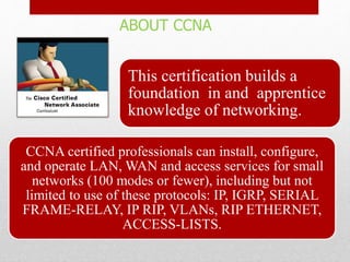
- An overview of the CCNA certification and what skills it demonstrates in networking areas like LANs, WANs, routing protocols, and network access.
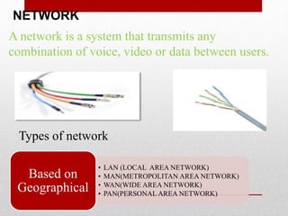
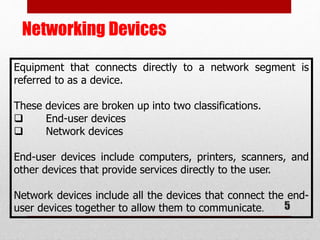
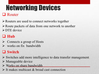
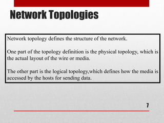
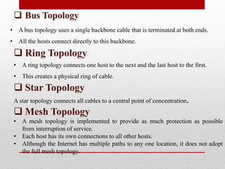
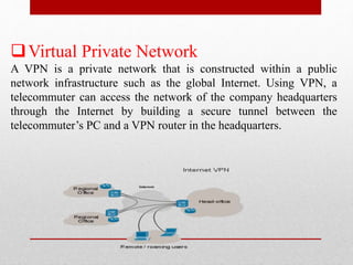
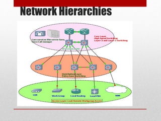
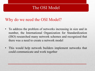
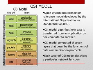
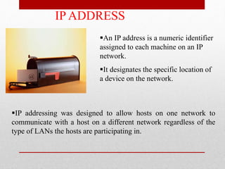
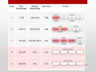
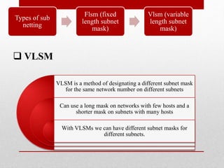
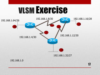
- Explanations of common networking devices, topologies, protocols like IP addressing and routing, and models like the OSI model.
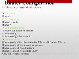
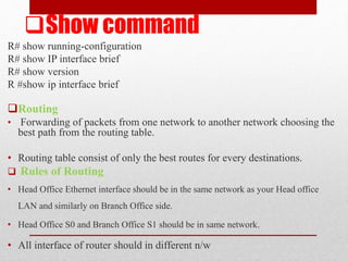
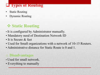
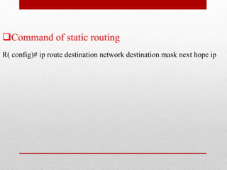
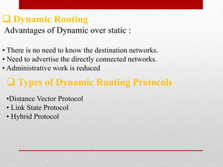
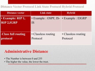
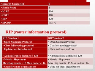
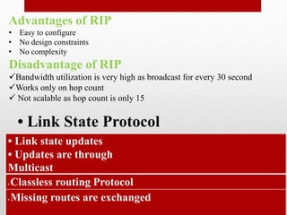
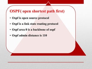
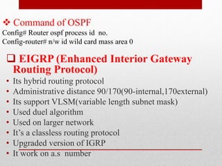
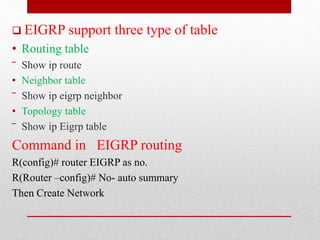
- Descriptions of static and dynamic routing, protocols like RIP, OSPF, EIGRP, and commands used to configure routers.