"LLMs for Python Engineers: Advanced Data Analysis and Semantic Kernel",Oleks...
Networking in college
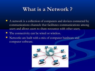
1. What is a Network ?
A network is a collection of computers and devices connected by
communications channels that facilitates communications among
users and allows users to share resources with other users.
The connectivity can be wired or wireless.
Networks are built with a mix of computer hardware and
computer software.
2. Network Classification
By Range:
By Functional Relationship:
Local Area Network ( LAN )
Metropolitan Area Network ( MAN )
Wide Area Network ( WAN )
Personal Area Network ( PAN )
Client-Server
Peer to Peer
By Network Topology:
Bus Networks
Star Networks
Ring Networks
3. Routing
Routing (or routeing) is the process of selecting
paths in a network along which to send network
traffic.
primarily with routing in electronic data
networks using packet switching technology.
Routing process usually directs forwarding of
packets on the basis of routing tables which
maintain a record of the routes to various
network destinations.
4. Classification of Routing
Based on the route telling scheme to the router
Static Routing
Routing tables are manually configured.
The advantage of this routing type is maximum
computing resources are saved but are conditioned.
Dynamic Routing
Routing tables are constructed automatically, based on
information carried by routing protocols.
Dynamic routing dominates the Internet because it allows
the network to act nearly autonomous in avoiding
network failures and blockages.
5. Dynamic Routing
Distance Vector
This approach assigns a number, the cost, to each of the links
between each node in the network.
Nodes will send information from point A to point B via the path
that results in the lowest total cost.
Link State
Each node uses as its fundamental data a map of the network in the
form of a graph.
Each router then independently determines the least-cost path from
itself to every other node using a standard shortest path algorithm
such as Dijkstra's algorithm.
The result is a tree which serves to construct the routing table, which
specifies the best next hop to get from the current node to any other
node.
6. Major Routing Protocols
Routing Information Protocol ( RIP )
Open Shortest Path First ( OSPF)
External Interior Gateway Routing Protocol
( EIGRP )
7. RIP
Random Facts:Is a Dynamic Routing Protocol
Uses Distance Vector Routing algorithm
RIP updates are used as keep alives and are periodic
Routing table is sent as updates
Hello Timer is 30 seconds
Dead(flush) Timer is 240 seconds i.e. 8 consecutive packets
Updates are UDP based and uses destination port no. 520
Hop Count is used as the metric
RIP v1 does not support subnetting
RIP v2 supports subnetting
8. OSPF
Random Facts:Is a Link State Routing Protocol
OSPF Hello Packets are used as keep alives
Hello Timer is 10 seconds
Dead Timers is 40 seconds i.e. 4 consecutive Hello Packets
Information of networks is sent only during neighbourship
establishment
Metric = cost = 100/Bandwidth in Mbps
Linked State Database(LSD) is formed from the Link State
Updates(LSU), from which graph of whole network is created
Auto-summarization is OFF by default
9. Access Lists
Is a group of permit/deny statements
The list is scanned from top to bottom--in the exact order that it
was entered for a pattern that matches the incoming packet
Can use a mask, which is like a wild card, to determine how
much of an IP source or destination address to apply to the
pattern match
To make a change, we have to re-enter the entire list
Any packet not processed by the list is dropped by default.
Is associated with an interface of the router, where we want to
filter the traffic.
Can be INBOUND i.e. applied for incoming traffic or
OUTBOUND i.e. applied for outgoing traffic of an interface
10. Types of Access List
Standard
Operates on the Network Layer (Layer 3)of the OSI model
Used to block/permit networks from reaching other networks
based on the source ip addresses and mask
Uses Access List range from 1 to 99
Extended
Operates on both Layer 3 and Layer 4 of OSI model
Allow us to filter traffic not only by network address but also by
the type of traffic that is being sent or received and also on the
basis of source as well as destination ip addresses and mask
Uses Access List Range from 100 to 199
11. Domain Name System( DNS)
Standard technology for managing the names of Web
sites and other Internet domain
DNS server is any computer registered to join the
Domain Name System
DNS server runs special-purpose networking software,
features a public ip address, and contains a database of
network names and addresses for other Internet hosts
DNS servers are organized in a hierarchy
At the top level of the hierarchy, so-called root
servers store the complete database of Internet domain
names and their corresponding IP addresses
DNS networking is based on
the client/serrver architecture
13. Certain Facts:The concepts of networking used to demonstrate and configure the networks are as
follows: Routing Protocols
Access-Lists
Link State Routing Protocol ( OSPF )
Distance Vector Routing Protocol ( RIP )
Standard
Extended
Domain Name System
The elements of networks used in the configuration are as follows: Routers ( Cisco 2811)
Switches ( Cisco 2960 24 TT )
Network Cables
Serial cables
Straight Ethernet Cables
Crossover Ethernet Cables
Servers
14. Constraints on the Network:
The DNS server is located in another Autonomous
System. We have to make sure that all users in the
college network get access to the DNS server.
Perform sufficient configuration at appropriate
places so that only the users in Department 1 get
access to the College web server.
Enable internet access for all the clients except
PC5 and PC6 in Department 2
15. Explanation: College Network
The college network comprises an autonomous system
which uses OSPF which is a Link State Routing
Protocol.
There are 2 routers used in the network.
10.0.0.0/8 network is used for connecting computers of
department 1, thus using class A private addresses.
192.168.21.0/24 network is used for connecting
computers of department 2, thus using class C private
addresses.
The College Server uses 22.0.0.0/8 network
17. Configuration of OSPF on Routers
To turn ON OSPF process globally on a router
Router# configure terminal
Router(conf)# router OSPF <process id>
Select the interfaces(networks) which we want to advertise
Router 1(conf-router)# network 10.0.0.0 0.255.255.255 area 0
10.0.0.0 – The network which we want to advertise and enable routing on.
0.255.255.255 – Wild Card Mask, allowing certain ip addresses to be
advertised.
Area 0 – The area ID, identifying all the machines in an area.
18. Routes at the College Router
The result of ‘show ip route’ command on College Router is:R2#show ip route
O 10.0.0.0/8 [110/65] via 20.0.0.1, 00:58:11, Serial0/1/1
C 20.0.0.0/8 is directly connected, Serial0/1/1
C 22.0.0.0/8 is directly connected, FastEthernet0/0
C 23.0.0.0/8 is directly connected, Serial0/1/0
O 30.0.0.0/8 [110/65] via 23.0.0.2, 00:58:11, Serial0/1/0
O E2 34.0.0.0/8 [110/20] via 23.0.0.2, 00:58:11, Serial0/1/0
O E2 35.0.0.0/8 [110/20] via 23.0.0.2, 00:58:11, Serial0/1/0
O E2 45.0.0.0/8 [110/20] via 23.0.0.2, 00:58:11, Serial0/1/0
O E2 56.0.0.0/8 [110/20] via 23.0.0.2, 00:58:11, Serial0/1/0
C 192.168.21.0/24 is directly connected, FastEthernet0/1
O*E2 0.0.0.0/0 [110/1] via 23.0.0.2, 00:58:11, Serial0/1/0
20. Configuration of RIP on Routers
To turn ON RIP process globally on a router
Router4# configure terminal
Router4(conf)# router RIP
Select the interfaces(networks) which we want to advertise
Router 4(conf-router)# network 34.0.0.0
Router 4(conf-router)# network 45.0.0.0
10.0.0.0 – The network which we want to advertise and enable routing on.
21. Routes at the ISP Router
The result of ‘show ip route’ command on an ISP Router is:R4#show ip route
R 10.0.0.0/8 [120/2] via 34.0.0.1, 00:00:29, Serial0/1/1
[120/2] via 45.0.0.1, 00:00:00, Serial0/0/0
R 20.0.0.0/8 [120/2] via 34.0.0.1, 00:00:29, Serial0/1/1
[120/2] via 45.0.0.1, 00:00:00, Serial0/0/0
R 22.0.0.0/8 [120/2] via 34.0.0.1, 00:00:29, Serial0/1/1
[120/2] via 45.0.0.1, 00:00:00, Serial0/0/0
R 23.0.0.0/8 [120/2] via 34.0.0.1, 00:00:24, Serial0/1/1
R 30.0.0.0/8 [120/2] via 34.0.0.1, 00:00:24, Serial0/1/1
C 34.0.0.0/8 is directly connected, Serial0/1/1
C 45.0.0.0/8 is directly connected, Serial0/0/0
R 56.0.0.0/8 [120/1] via 45.0.0.1, 00:00:00, Serial0/0/0
R 192.168.21.0/24 [120/2] via 34.0.0.1, 00:00:29, Serial0/1/1
[120/2] via 45.0.0.1, 00:00:00, Serial0/0/0
R* 0.0.0.0/0 [120/1] via 45.0.0.1, 00:00:00, Serial0/0/0
24. Entries of Access Lists:
Access List 100 used for applying the second constraint
R2#show ip access-lists 100
Extended IP access list 100
deny tcp host 192.168.21.50 host 60.0.0.60
deny tcp host 192.168.21.60 host 60.0.0.60
deny tcp host 192.168.21.60 host 70.0.0.70
deny tcp host 192.168.21.50 host 70.0.0.70
permit ip any any
Access List 101 used for applying the third constraint
R2#show ip access-lists 101
Extended IP access list 101
permit ip 10.0.0.0 0.255.255.255 host 22.0.0.2
deny ip any any
25. Different parts of an Access List
deny tcp host 192.168.21.50 host 60.0.0.60
Deny – Specifies the permission whether to permit/deny the access
Tcp – This specifies the type of traffic we want to permit/deny
The type of traffic we can control is:IP – Represents all the traffic flowing on the internet.
TCP – Represents only the packets which use Transmission Control Protocol
UDP - Represents only the packets which use the User Datagram Protocol
ICMP - Represents only the packets which use Internet Control Message Protocol
Host 192.168.21.50 – This section specifies the source machine we want to control
access to
Host 60.0.0.60 - This section specifies the destination machine we want to control
access to
Instead, if we want to control the access to all the machines, we do it by writing ‘any’
like:-
Permit ip any any