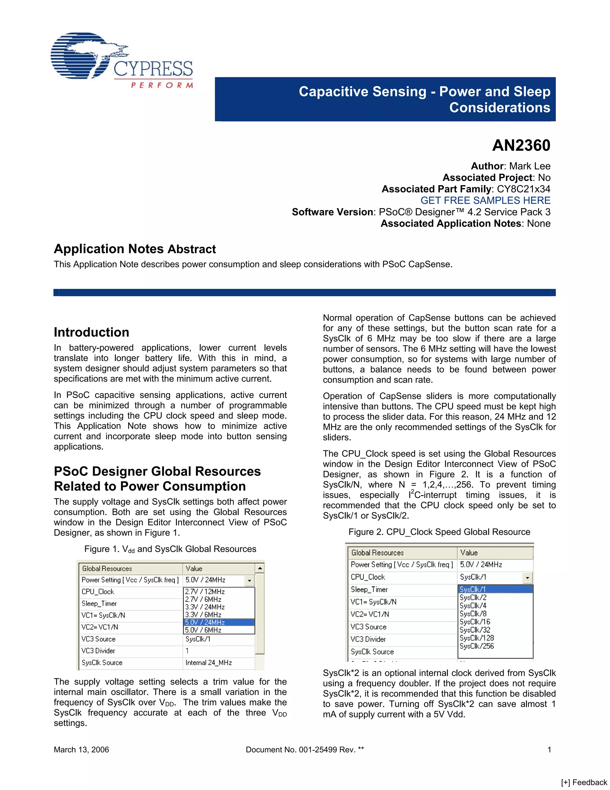
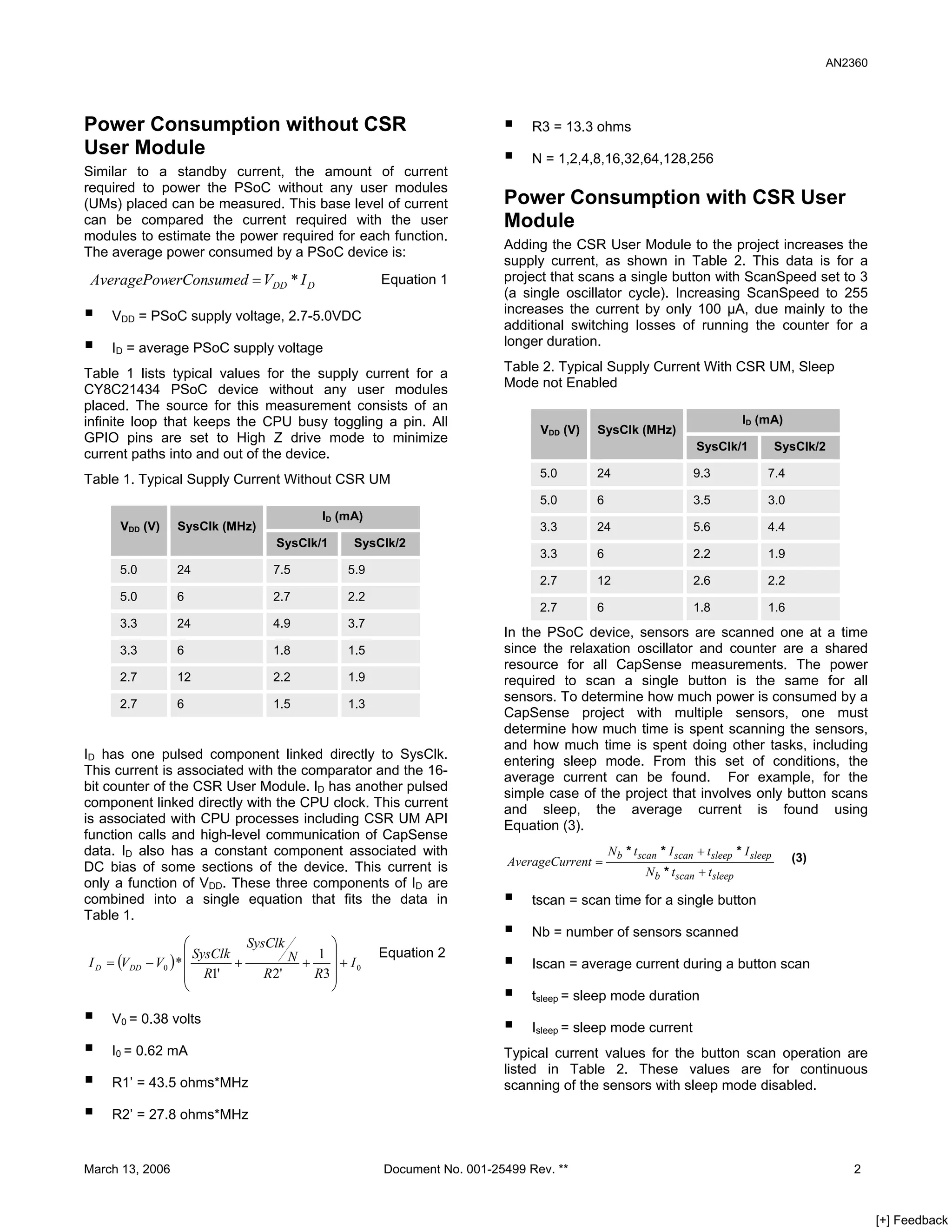
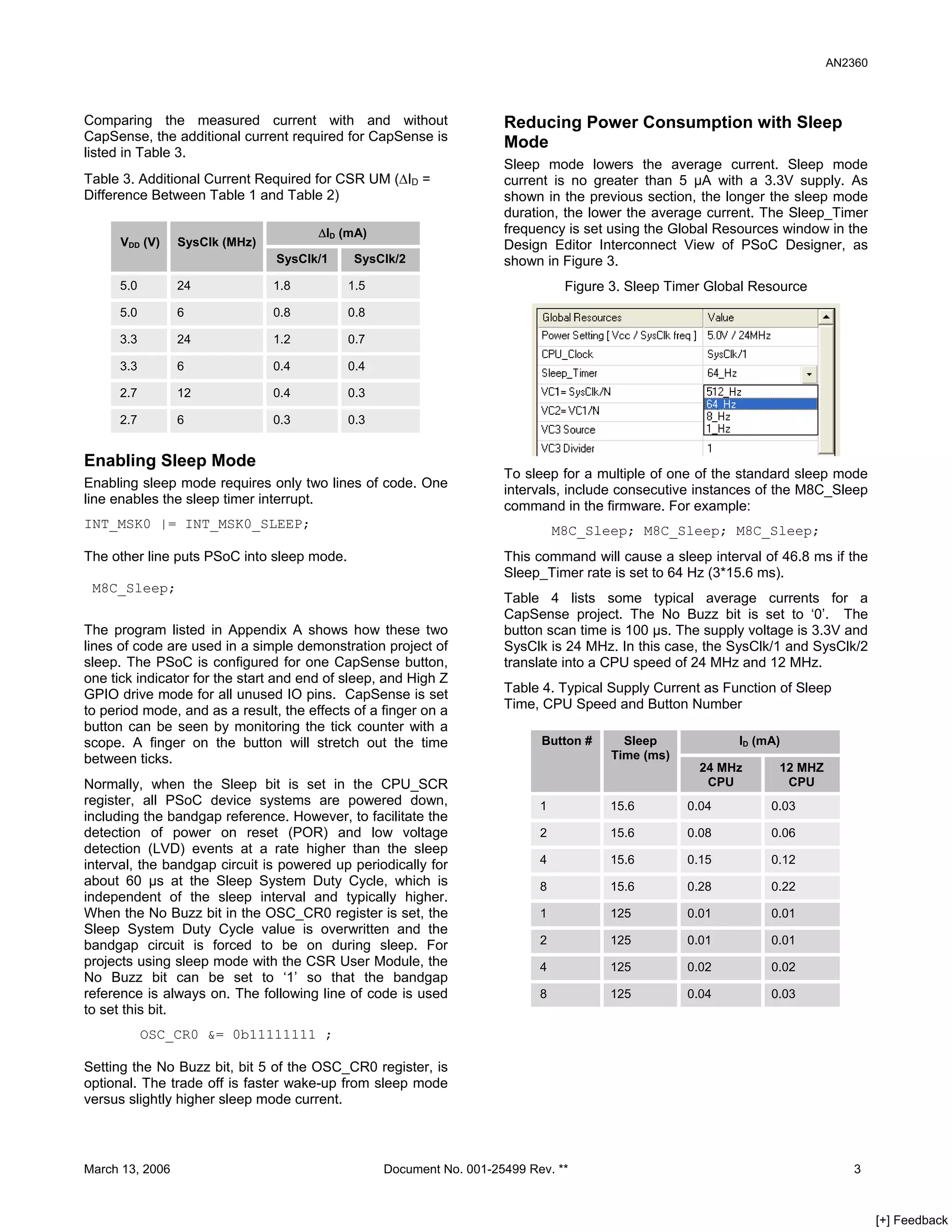
SlideShare a Scribd company logo
Capacitive Sensing - Power and Sleep
                                                                                     Considerations

                                                                                                              AN2360
                                                                                                  Author: Mark Lee
                                                                                            Associated Project: No
                                                                                Associated Part Family: CY8C21x34
                                                                                        GET FREE SAMPLES HERE
                                                              Software Version: PSoC® Designer™ 4.2 Service Pack 3
                                                                                Associated Application Notes: None

Application Notes Abstract
This Application Note describes power consumption and sleep considerations with PSoC CapSense.


                                                                    Normal operation of CapSense buttons can be achieved
                                                                    for any of these settings, but the button scan rate for a
Introduction                                                        SysClk of 6 MHz may be too slow if there are a large
In battery-powered applications, lower current levels               number of sensors. The 6 MHz setting will have the lowest
translate into longer battery life. With this in mind, a            power consumption, so for systems with large number of
system designer should adjust system parameters so that             buttons, a balance needs to be found between power
specifications are met with the minimum active current.             consumption and scan rate.
In PSoC capacitive sensing applications, active current             Operation of CapSense sliders is more computationally
can be minimized through a number of programmable                   intensive than buttons. The CPU speed must be kept high
settings including the CPU clock speed and sleep mode.              to process the slider data. For this reason, 24 MHz and 12
This Application Note shows how to minimize active                  MHz are the only recommended settings of the SysClk for
current and incorporate sleep mode into button sensing              sliders.
applications.
                                                                    The CPU_Clock speed is set using the Global Resources
                                                                    window in the Design Editor Interconnect View of PSoC
PSoC Designer Global Resources                                      Designer, as shown in Figure 2. It is a function of
                                                                    SysClk/N, where N = 1,2,4,…,256. To prevent timing
Related to Power Consumption
                                                                    issues, especially I2C-interrupt timing issues, it is
The supply voltage and SysClk settings both affect power            recommended that the CPU clock speed only be set to
consumption. Both are set using the Global Resources                SysClk/1 or SysClk/2.
window in the Design Editor Interconnect View of PSoC
                                                                          Figure 2. CPU_Clock Speed Global Resource
Designer, as shown in Figure 1.
       Figure 1. Vdd and SysClk Global Resources


                                                                    SysClk*2 is an optional internal clock derived from SysClk
The supply voltage setting selects a trim value for the             using a frequency doubler. If the project does not require
internal main oscillator. There is a small variation in the         SysClk*2, it is recommended that this function be disabled
frequency of SysClk over VDD. The trim values make the              to save power. Turning off SysClk*2 can save almost 1
SysClk frequency accurate at each of the three VDD                  mA of supply current with a 5V Vdd.
settings.

March 13, 2006                                  Document No. 001-25499 Rev. **                                             1


                                                                                                                                 [+] Feedback
AN2360


Power Consumption without CSR                                                R3 = 13.3 ohms
User Module                                                                  N = 1,2,4,8,16,32,64,128,256
Similar to a standby current, the amount of current
required to power the PSoC without any user modules
                                                                        Power Consumption with CSR User
(UMs) placed can be measured. This base level of current
can be compared the current required with the user                      Module
modules to estimate the power required for each function.
                                                                        Adding the CSR User Module to the project increases the
The average power consumed by a PSoC device is:
                                                                        supply current, as shown in Table 2. This data is for a
                                                                        project that scans a single button with ScanSpeed set to 3
 AveragePowerConsumed = VDD * I D                    Equation 1
                                                                        (a single oscillator cycle). Increasing ScanSpeed to 255
                                                                        increases the current by only 100 μA, due mainly to the
    VDD = PSoC supply voltage, 2.7-5.0VDC
                                                                        additional switching losses of running the counter for a
                                                                        longer duration.
    ID = average PSoC supply voltage
                                                                        Table 2. Typical Supply Current With CSR UM, Sleep
Table 1 lists typical values for the supply current for a
                                                                        Mode not Enabled
CY8C21434 PSoC device without any user modules
placed. The source for this measurement consists of an
infinite loop that keeps the CPU busy toggling a pin. All                                                                     ID (mA)
                                                                              VDD (V)   SysClk (MHz)
GPIO pins are set to High Z drive mode to minimize
                                                                                                                  SysClk/1              SysClk/2
current paths into and out of the device.
                                                                              5.0       24                       9.3                7.4
Table 1. Typical Supply Current Without CSR UM
                                                                              5.0       6                        3.5                3.0
                                           ID (mA)
                                                                              3.3       24                       5.6                4.4
      VDD (V)     SysClk (MHz)
                                   SysClk/1     SysClk/2
                                                                              3.3       6                        2.2                1.9
     5.0          24              7.5          5.9
                                                                              2.7       12                       2.6                2.2
     5.0          6               2.7          2.2
                                                                              2.7       6                        1.8                1.6
     3.3          24              4.9          3.7
                                                                        In the PSoC device, sensors are scanned one at a time
                                                                        since the relaxation oscillator and counter are a shared
     3.3          6               1.8          1.5
                                                                        resource for all CapSense measurements. The power
     2.7          12              2.2          1.9                      required to scan a single button is the same for all
                                                                        sensors. To determine how much power is consumed by a
     2.7          6               1.5          1.3
                                                                        CapSense project with multiple sensors, one must
                                                                        determine how much time is spent scanning the sensors,
                                                                        and how much time is spent doing other tasks, including
ID has one pulsed component linked directly to SysClk.                  entering sleep mode. From this set of conditions, the
This current is associated with the comparator and the 16-              average current can be found. For example, for the
bit counter of the CSR User Module. ID has another pulsed               simple case of the project that involves only button scans
component linked directly with the CPU clock. This current              and sleep, the average current is found using
is associated with CPU processes including CSR UM API                   Equation (3).
function calls and high-level communication of CapSense
                                                                                            N b * t scan * I scan + t sleep * I sleep
data. ID also has a constant component associated with
                                                                         AverageCurrent =                                                 (3)
DC bias of some sections of the device. This current is                                              N b * t scan + t sleep
only a function of VDD. These three components of ID are
combined into a single equation that fits the data in                        tscan = scan time for a single button
Table 1.
                                                                             Nb = number of sensors scanned
                      ⎛                         ⎞
                                 SysClk
                      ⎜ SysClk           N + 1 ⎟+I   Equation 2
I D = (VDD   − V0 ) * ⎜        +                                             Iscan = average current during a button scan
                                                ⎟0
                      ⎜ R1'                  R3 ⎟
                                    R 2'
                      ⎝                         ⎠
                                                                             tsleep = sleep mode duration
    V0 = 0.38 volts
                                                                             Isleep = sleep mode current
    I0 = 0.62 mA                                                        Typical current values for the button scan operation are
                                                                        listed in Table 2. These values are for continuous
    R1’ = 43.5 ohms*MHz                                                 scanning of the sensors with sleep mode disabled.

    R2’ = 27.8 ohms*MHz


March 13, 2006                                       Document No. 001-25499 Rev. **                                                                 2


                                                                                                                                                         [+] Feedback
AN2360


Comparing the measured current with and without                      Reducing Power Consumption with Sleep
CapSense, the additional current required for CapSense is            Mode
listed in Table 3.
                                                                     Sleep mode lowers the average current. Sleep mode
Table 3. Additional Current Required for CSR UM (ΔID =               current is no greater than 5 μA with a 3.3V supply. As
Difference Between Table 1 and Table 2)                              shown in the previous section, the longer the sleep mode
                                                                     duration, the lower the average current. The Sleep_Timer
                                                                     frequency is set using the Global Resources window in the
                                       ΔID (mA)
                                                                     Design Editor Interconnect View of PSoC Designer, as
      VDD (V)    SysClk (MHz)
                                                                     shown in Figure 3.
                                SysClk/1     SysClk/2

                                                                                Figure 3. Sleep Timer Global Resource
      5.0        24             1.8         1.5

      5.0        6              0.8         0.8

      3.3        24             1.2         0.7

      3.3        6              0.4         0.4

      2.7        12             0.4         0.3

      2.7        6              0.3         0.3


Enabling Sleep Mode
                                                                     To sleep for a multiple of one of the standard sleep mode
Enabling sleep mode requires only two lines of code. One             intervals, include consecutive instances of the M8C_Sleep
line enables the sleep timer interrupt.                              command in the firmware. For example:
INT_MSK0 |= INT_MSK0_SLEEP;                                                    M8C_Sleep; M8C_Sleep; M8C_Sleep;
The other line puts PSoC into sleep mode.                            This command will cause a sleep interval of 46.8 ms if the
                                                                     Sleep_Timer rate is set to 64 Hz (3*15.6 ms).
 M8C_Sleep;
                                                                     Table 4 lists some typical average currents for a
                                                                     CapSense project. The No Buzz bit is set to ‘0’. The
The program listed in Appendix A shows how these two                 button scan time is 100 μs. The supply voltage is 3.3V and
lines of code are used in a simple demonstration project of          SysClk is 24 MHz. In this case, the SysClk/1 and SysClk/2
sleep. The PSoC is configured for one CapSense button,               translate into a CPU speed of 24 MHz and 12 MHz.
one tick indicator for the start and end of sleep, and High Z
                                                                     Table 4. Typical Supply Current as Function of Sleep
GPIO drive mode for all unused IO pins. CapSense is set
                                                                     Time, CPU Speed and Button Number
to period mode, and as a result, the effects of a finger on a
button can be seen by monitoring the tick counter with a
scope. A finger on the button will stretch out the time                    Button #      Sleep            ID (mA)
                                                                                       Time (ms)
between ticks.
                                                                                                     24 MHz     12 MHZ
Normally, when the Sleep bit is set in the CPU_SCR                                                    CPU        CPU
register, all PSoC device systems are powered down,                        1          15.6         0.04        0.03
including the bandgap reference. However, to facilitate the
detection of power on reset (POR) and low voltage                          2          15.6         0.08        0.06
detection (LVD) events at a rate higher than the sleep
                                                                           4          15.6         0.15        0.12
interval, the bandgap circuit is powered up periodically for
about 60 μs at the Sleep System Duty Cycle, which is                       8          15.6         0.28        0.22
independent of the sleep interval and typically higher.
When the No Buzz bit in the OSC_CR0 register is set, the                   1          125          0.01        0.01
Sleep System Duty Cycle value is overwritten and the
                                                                           2          125          0.01        0.01
bandgap circuit is forced to be on during sleep. For
projects using sleep mode with the CSR User Module, the                    4          125          0.02        0.02
No Buzz bit can be set to ‘1’ so that the bandgap
reference is always on. The following line of code is used                 8          125          0.04        0.03
to set this bit.
            OSC_CR0 &= 0b11111111 ;

Setting the No Buzz bit, bit 5 of the OSC_CR0 register, is
optional. The trade off is faster wake-up from sleep mode
versus slightly higher sleep mode current.


March 13, 2006                                    Document No. 001-25499 Rev. **                                             3


                                                                                                                                  [+] Feedback
AN2360


Summary
Sleep mode is an effective method for extending battery
life in PSoC applications with CapSense. Two important
system parameters that affect battery life are the supply
voltage and the CPU speed. Design equations are
presented that quantify the effect of these two parameters
on the supply current. The number of sensors scanned
influences the average current in sleep mode. More
buttons translate into longer scan rates or higher average
current. Through minor firmware adjustments, the system
designer can find the right balance between scan rate and
current. The ability of PSoC to adapt to changing
requirements through firmware is a big asset to engineers
designing CapSense systems for long battery life.


March 13, 2006                                 Document No. 001-25499 Rev. **       4


                                                                                         [+] Feedback
AN2360


Appendix. Sleep Mode Example Firmware Listing
//--- Sleep Mode example, main.c, for CY8C21434 PSoC
#include <m8c.h>        // part specific constants and macros
#include quot;PSoCAPI.hquot;    // PSoC API definitions for all User Modules
void main()
{
  INT_MSK0 |= INT_MSK0_SLEEP ;

//P1[1] toggles to indicate start and end   of sleep
//P0[4] has capsense button
//all other ports set to Hi-Z to minimize   current
  PRT3DM0=0b00000000; PRT3DM1=0b11111111;   PRT3DM2=0b11111111;     PRT3DR=0b00000000;
  PRT2DM0=0b00000000; PRT2DM1=0b11111111;   PRT2DM2=0b11111111;     PRT2DR=0b00000000;
  PRT1DM0=0b00000010; PRT1DM1=0b11111101;   PRT1DM2=0b11111101;     PRT1DR=0b00000000;
  PRT0DM0=0b00010000; PRT0DM1=0b11101111;   PRT0DM2=0b11101111;     PRT0DR=0b00000000;

  CSR_1_Start(); CSR_1_SetDacCurrent(0x10,0); CSR_1_SetScanSpeed(3);
  M8C_EnableGInt;

  while(1)
  {
// Scan only switch 0
    CSR_1_StartScan(0,1,0);
// stall until the button 0 scan are finished
    while(!(CSR_1_GetScanStatus() & CSR_1_SCAN_SET_COMPLETE));

//mark start of sleep
    PRT1DR=0b00000010; PRT1DR=0b00000000;
    M8C_Sleep;
//mark end of sleep
    PRT1DR=0b00000010; PRT1DR=0b00000000;
  }
}


March 13, 2006                     Document No. 001-25499 Rev. **                            5


                                                                                                  [+] Feedback
AN2360


About the Author
                      Mark Lee
        Name:
                      Senior Application Engineer
          Title:
                      olr@cypress.com
       Contact:


In March of 2007, Cypress recataloged all of its Application Notes using a new documentation number and revision code. This new
documentation number and revision code (001-xxxxx, beginning with rev. **), located in the footer of the document, will be used in all
subsequent revisions.
PSoC is a registered trademark of Cypress Semiconductor Corp. quot;Programmable System-on-Chip,quot; PSoC Designer, and PSoC Express are
trademarks of Cypress Semiconductor Corp. All other trademarks or registered trademarks referenced herein are the property of their
respective owners.


                                                                                                                                 Cypress Semiconductor
                                                                                                                                    198 Champion Court
                                                                                                                               San Jose, CA 95134-1709
                                                                                                                                   Phone: 408-943-2600
                                                                                                                                       Fax: 408-943-4730
                                                                                                                                http://www.cypress.com/


© Cypress Semiconductor Corporation, 2006-2007. The information contained herein is subject to change without notice. Cypress Semiconductor
Corporation assumes no responsibility for the use of any circuitry other than circuitry embodied in a Cypress product. Nor does it convey or imply any
license under patent or other rights. Cypress products are not warranted nor intended to be used for medical, life support, life saving, critical control or
safety applications, unless pursuant to an express written agreement with Cypress. Furthermore, Cypress does not authorize its products for use as
critical components in life-support systems where a malfunction or failure may reasonably be expected to result in significant injury to the user. The
inclusion of Cypress products in life-support systems application implies that the manufacturer assumes all risk of such use and in doing so indemnifies
Cypress against all charges.
This Source Code (software and/or firmware) is owned by Cypress Semiconductor Corporation (Cypress) and is protected by and subject to worldwide
patent protection (United States and foreign), United States copyright laws and international treaty provisions. Cypress hereby grants to licensee a
personal, non-exclusive, non-transferable license to copy, use, modify, create derivative works of, and compile the Cypress Source Code and derivative
works for the sole purpose of creating custom software and or firmware in support of licensee product to be used only in conjunction with a Cypress
integrated circuit as specified in the applicable agreement. Any reproduction, modification, translation, compilation, or representation of this Source
Code except as specified above is prohibited without the express written permission of Cypress.
Disclaimer: CYPRESS MAKES NO WARRANTY OF ANY KIND, EXPRESS OR IMPLIED, WITH REGARD TO THIS MATERIAL, INCLUDING, BUT
NOT LIMITED TO, THE IMPLIED WARRANTIES OF MERCHANTABILITY AND FITNESS FOR A PARTICULAR PURPOSE. Cypress reserves the
right to make changes without further notice to the materials described herein. Cypress does not assume any liability arising out of the application or
use of any product or circuit described herein. Cypress does not authorize its products for use as critical components in life-support systems where a
malfunction or failure may reasonably be expected to result in significant injury to the user. The inclusion of Cypress’ product in a life-support systems
application implies that the manufacturer assumes all risk of such use and in doing so indemnifies Cypress against all charges.
Use may be limited by and subject to the applicable Cypress software license agreement.


March 13, 2006                                             Document No. 001-25499 Rev. **                                                                6


                                                                                                                                                               [+] Feedback

More Related Content

What's hot

Az25308314
Az25308314Az25308314
Az25308314
IJERA Editor
 
IJERD (www.ijerd.com) International Journal of Engineering Research and Devel...
IJERD (www.ijerd.com) International Journal of Engineering Research and Devel...IJERD (www.ijerd.com) International Journal of Engineering Research and Devel...
IJERD (www.ijerd.com) International Journal of Engineering Research and Devel...
IJERD Editor
 
Schneider Presentation Seattle 2011
Schneider Presentation Seattle 2011Schneider Presentation Seattle 2011
Schneider Presentation Seattle 2011
wlambert_2001
 
Low power vlsi design
Low power vlsi designLow power vlsi design
Low power vlsi design
Vinchipsytm Vlsitraining
 
An Internal Current Controlled BLDC Motor Drive Supplied with PV Fed High Vol...
An Internal Current Controlled BLDC Motor Drive Supplied with PV Fed High Vol...An Internal Current Controlled BLDC Motor Drive Supplied with PV Fed High Vol...
An Internal Current Controlled BLDC Motor Drive Supplied with PV Fed High Vol...
IJECEIAES
 
Nabeelpbm1998@gmail.com
Nabeelpbm1998@gmail.comNabeelpbm1998@gmail.com
Nabeelpbm1998@gmail.com
nabeelavulan
 
As32300306
As32300306As32300306
As32300306
IJERA Editor
 
Simplified cascade multiphase DC-DC boost power converters for high voltage-g...
Simplified cascade multiphase DC-DC boost power converters for high voltage-g...Simplified cascade multiphase DC-DC boost power converters for high voltage-g...
Simplified cascade multiphase DC-DC boost power converters for high voltage-g...
International Journal of Power Electronics and Drive Systems
 
EDS_REPORT_FINAL
EDS_REPORT_FINALEDS_REPORT_FINAL
EDS_REPORT_FINAL
ebbin daniel
 
Il3115821590
Il3115821590Il3115821590
Il3115821590
IJERA Editor
 
K044025559
K044025559K044025559
K044025559
IJERA Editor
 
J0372049056
J0372049056J0372049056
J0372049056
inventionjournals
 
International Journal of Engineering Research and Development (IJERD)
International Journal of Engineering Research and Development (IJERD)International Journal of Engineering Research and Development (IJERD)
International Journal of Engineering Research and Development (IJERD)
IJERD Editor
 
Improved Power Gating Technique for Leakage Power Reduction
Improved Power Gating Technique for Leakage Power ReductionImproved Power Gating Technique for Leakage Power Reduction
Improved Power Gating Technique for Leakage Power Reduction
inventy
 
Improved Power Gating Techniques for Reduction of Noise and Leakage Power in ...
Improved Power Gating Techniques for Reduction of Noise and Leakage Power in ...Improved Power Gating Techniques for Reduction of Noise and Leakage Power in ...
Improved Power Gating Techniques for Reduction of Noise and Leakage Power in ...
Associate Professor in VSB Coimbatore
 
Input devices power
Input devices powerInput devices power
Input devices power
Jeff Valerio
 
IRJET- A Review on Improvement of Power Quality and Displacement Factor u...
IRJET-  	  A Review on Improvement of Power Quality and Displacement Factor u...IRJET-  	  A Review on Improvement of Power Quality and Displacement Factor u...
IRJET- A Review on Improvement of Power Quality and Displacement Factor u...
IRJET Journal
 
IRJET- Design and Implementaion of DC-DC Boost Converter using Output Voltage...
IRJET- Design and Implementaion of DC-DC Boost Converter using Output Voltage...IRJET- Design and Implementaion of DC-DC Boost Converter using Output Voltage...
IRJET- Design and Implementaion of DC-DC Boost Converter using Output Voltage...
IRJET Journal
 

What's hot (18)

Az25308314
Az25308314Az25308314
Az25308314
 
IJERD (www.ijerd.com) International Journal of Engineering Research and Devel...
IJERD (www.ijerd.com) International Journal of Engineering Research and Devel...IJERD (www.ijerd.com) International Journal of Engineering Research and Devel...
IJERD (www.ijerd.com) International Journal of Engineering Research and Devel...
 
Schneider Presentation Seattle 2011
Schneider Presentation Seattle 2011Schneider Presentation Seattle 2011
Schneider Presentation Seattle 2011
 
Low power vlsi design
Low power vlsi designLow power vlsi design
Low power vlsi design
 
An Internal Current Controlled BLDC Motor Drive Supplied with PV Fed High Vol...
An Internal Current Controlled BLDC Motor Drive Supplied with PV Fed High Vol...An Internal Current Controlled BLDC Motor Drive Supplied with PV Fed High Vol...
An Internal Current Controlled BLDC Motor Drive Supplied with PV Fed High Vol...
 
Nabeelpbm1998@gmail.com
Nabeelpbm1998@gmail.comNabeelpbm1998@gmail.com
Nabeelpbm1998@gmail.com
 
As32300306
As32300306As32300306
As32300306
 
Simplified cascade multiphase DC-DC boost power converters for high voltage-g...
Simplified cascade multiphase DC-DC boost power converters for high voltage-g...Simplified cascade multiphase DC-DC boost power converters for high voltage-g...
Simplified cascade multiphase DC-DC boost power converters for high voltage-g...
 
EDS_REPORT_FINAL
EDS_REPORT_FINALEDS_REPORT_FINAL
EDS_REPORT_FINAL
 
Il3115821590
Il3115821590Il3115821590
Il3115821590
 
K044025559
K044025559K044025559
K044025559
 
J0372049056
J0372049056J0372049056
J0372049056
 
International Journal of Engineering Research and Development (IJERD)
International Journal of Engineering Research and Development (IJERD)International Journal of Engineering Research and Development (IJERD)
International Journal of Engineering Research and Development (IJERD)
 
Improved Power Gating Technique for Leakage Power Reduction
Improved Power Gating Technique for Leakage Power ReductionImproved Power Gating Technique for Leakage Power Reduction
Improved Power Gating Technique for Leakage Power Reduction
 
Improved Power Gating Techniques for Reduction of Noise and Leakage Power in ...
Improved Power Gating Techniques for Reduction of Noise and Leakage Power in ...Improved Power Gating Techniques for Reduction of Noise and Leakage Power in ...
Improved Power Gating Techniques for Reduction of Noise and Leakage Power in ...
 
Input devices power
Input devices powerInput devices power
Input devices power
 
IRJET- A Review on Improvement of Power Quality and Displacement Factor u...
IRJET-  	  A Review on Improvement of Power Quality and Displacement Factor u...IRJET-  	  A Review on Improvement of Power Quality and Displacement Factor u...
IRJET- A Review on Improvement of Power Quality and Displacement Factor u...
 
IRJET- Design and Implementaion of DC-DC Boost Converter using Output Voltage...
IRJET- Design and Implementaion of DC-DC Boost Converter using Output Voltage...IRJET- Design and Implementaion of DC-DC Boost Converter using Output Voltage...
IRJET- Design and Implementaion of DC-DC Boost Converter using Output Voltage...
 

Viewers also liked

Coin based mobile charger project report
Coin based mobile charger project reportCoin based mobile charger project report
Coin based mobile charger project report
kaushal chaubey
 
Bluetooth controlled home appliances
Bluetooth controlled home appliancesBluetooth controlled home appliances
Bluetooth controlled home appliances
ADARSH KUMAR
 
HOME AUTOMATION USING ANDROID PHONE OVER BLUETOOTH
HOME AUTOMATION USING ANDROID PHONE OVER BLUETOOTHHOME AUTOMATION USING ANDROID PHONE OVER BLUETOOTH
HOME AUTOMATION USING ANDROID PHONE OVER BLUETOOTH
Subhash Kumar Yadav
 
Vehicle accident detection and messaging system using GSM and arduino
Vehicle accident detection and messaging system using GSM and arduinoVehicle accident detection and messaging system using GSM and arduino
Vehicle accident detection and messaging system using GSM and arduino
Ramesh Reddy
 
Project report for railway security monotorin system
Project report for railway security monotorin systemProject report for railway security monotorin system
Project report for railway security monotorin system
ASWATHY VG
 
A minor project report HOME AUTOMATION USING MOBILE PHONES
A minor project report HOME AUTOMATION  USING  MOBILE PHONESA minor project report HOME AUTOMATION  USING  MOBILE PHONES
A minor project report HOME AUTOMATION USING MOBILE PHONES
ashokkok
 
Presentation on home automation
Presentation on home automationPresentation on home automation
Presentation on home automation
Subhash Kumar Yadav
 
Vehicle tracking system using gps and gsm
Vehicle tracking system using gps and gsmVehicle tracking system using gps and gsm
Vehicle tracking system using gps and gsm
anita maharjan
 
ACCIDENT DETECTION AND VEHICLE TRACKING USING GPS,GSM AND MEMS
ACCIDENT DETECTION AND VEHICLE TRACKING USING GPS,GSM AND MEMSACCIDENT DETECTION AND VEHICLE TRACKING USING GPS,GSM AND MEMS
ACCIDENT DETECTION AND VEHICLE TRACKING USING GPS,GSM AND MEMS
Krishna Moparthi
 
Automatic vehicle accident detection and messaging system using gsm and gps m...
Automatic vehicle accident detection and messaging system using gsm and gps m...Automatic vehicle accident detection and messaging system using gsm and gps m...
Automatic vehicle accident detection and messaging system using gsm and gps m...
mahesh_rman
 
coin based mobile battery charger
coin based mobile battery chargercoin based mobile battery charger
coin based mobile battery charger
ullekh
 
Presentation Smart Home With Home Automation
Presentation Smart Home With Home AutomationPresentation Smart Home With Home Automation
Presentation Smart Home With Home Automation
Arifur Rahman
 
My Final Year Project - Individual Control Home Automation System
My Final Year Project - Individual Control Home Automation SystemMy Final Year Project - Individual Control Home Automation System
My Final Year Project - Individual Control Home Automation System
Michael Olafusi
 
Vehicle tracking system using gps and gsm techniques
Vehicle tracking system using gps and gsm techniquesVehicle tracking system using gps and gsm techniques
Vehicle tracking system using gps and gsm techniques
Bharath Chapala
 

Viewers also liked (14)

Coin based mobile charger project report
Coin based mobile charger project reportCoin based mobile charger project report
Coin based mobile charger project report
 
Bluetooth controlled home appliances
Bluetooth controlled home appliancesBluetooth controlled home appliances
Bluetooth controlled home appliances
 
HOME AUTOMATION USING ANDROID PHONE OVER BLUETOOTH
HOME AUTOMATION USING ANDROID PHONE OVER BLUETOOTHHOME AUTOMATION USING ANDROID PHONE OVER BLUETOOTH
HOME AUTOMATION USING ANDROID PHONE OVER BLUETOOTH
 
Vehicle accident detection and messaging system using GSM and arduino
Vehicle accident detection and messaging system using GSM and arduinoVehicle accident detection and messaging system using GSM and arduino
Vehicle accident detection and messaging system using GSM and arduino
 
Project report for railway security monotorin system
Project report for railway security monotorin systemProject report for railway security monotorin system
Project report for railway security monotorin system
 
A minor project report HOME AUTOMATION USING MOBILE PHONES
A minor project report HOME AUTOMATION  USING  MOBILE PHONESA minor project report HOME AUTOMATION  USING  MOBILE PHONES
A minor project report HOME AUTOMATION USING MOBILE PHONES
 
Presentation on home automation
Presentation on home automationPresentation on home automation
Presentation on home automation
 
Vehicle tracking system using gps and gsm
Vehicle tracking system using gps and gsmVehicle tracking system using gps and gsm
Vehicle tracking system using gps and gsm
 
ACCIDENT DETECTION AND VEHICLE TRACKING USING GPS,GSM AND MEMS
ACCIDENT DETECTION AND VEHICLE TRACKING USING GPS,GSM AND MEMSACCIDENT DETECTION AND VEHICLE TRACKING USING GPS,GSM AND MEMS
ACCIDENT DETECTION AND VEHICLE TRACKING USING GPS,GSM AND MEMS
 
Automatic vehicle accident detection and messaging system using gsm and gps m...
Automatic vehicle accident detection and messaging system using gsm and gps m...Automatic vehicle accident detection and messaging system using gsm and gps m...
Automatic vehicle accident detection and messaging system using gsm and gps m...
 
coin based mobile battery charger
coin based mobile battery chargercoin based mobile battery charger
coin based mobile battery charger
 
Presentation Smart Home With Home Automation
Presentation Smart Home With Home AutomationPresentation Smart Home With Home Automation
Presentation Smart Home With Home Automation
 
My Final Year Project - Individual Control Home Automation System
My Final Year Project - Individual Control Home Automation SystemMy Final Year Project - Individual Control Home Automation System
My Final Year Project - Individual Control Home Automation System
 
Vehicle tracking system using gps and gsm techniques
Vehicle tracking system using gps and gsm techniquesVehicle tracking system using gps and gsm techniques
Vehicle tracking system using gps and gsm techniques
 

Similar to Capacitive Sensing - Power and Sleep Considerations

CapSense Capacitive Sensing Best Practices
CapSense Capacitive Sensing Best PracticesCapSense Capacitive Sensing Best Practices
CapSense Capacitive Sensing Best Practices
Ruth Moore
 
Capacitance Sensing - Migrating from CSR to CSA
Capacitance Sensing - Migrating from CSR to CSACapacitance Sensing - Migrating from CSR to CSA
Capacitance Sensing - Migrating from CSR to CSA
emilyjoseph444
 
International Journal of Engineering Research and Development
International Journal of Engineering Research and DevelopmentInternational Journal of Engineering Research and Development
International Journal of Engineering Research and Development
IJERD Editor
 
Design and simulation of Arduino Nano controlled DC-DC converters for low and...
Design and simulation of Arduino Nano controlled DC-DC converters for low and...Design and simulation of Arduino Nano controlled DC-DC converters for low and...
Design and simulation of Arduino Nano controlled DC-DC converters for low and...
IJECEIAES
 
Capacitance Sensing Migrating From Csr To Csd An2408 12
Capacitance Sensing   Migrating From Csr To Csd   An2408 12Capacitance Sensing   Migrating From Csr To Csd   An2408 12
Capacitance Sensing Migrating From Csr To Csd An2408 12
Ruth Moore
 
Ff25965968
Ff25965968Ff25965968
Ff25965968
IJERA Editor
 
Ijarcet vol-2-issue-7-2241-2245
Ijarcet vol-2-issue-7-2241-2245Ijarcet vol-2-issue-7-2241-2245
Ijarcet vol-2-issue-7-2241-2245
Editor IJARCET
 
Ijarcet vol-2-issue-7-2241-2245
Ijarcet vol-2-issue-7-2241-2245Ijarcet vol-2-issue-7-2241-2245
Ijarcet vol-2-issue-7-2241-2245
Editor IJARCET
 
CapSense Capacitive Sensors Sigma Delta Algorithm
CapSense Capacitive Sensors Sigma Delta AlgorithmCapSense Capacitive Sensors Sigma Delta Algorithm
CapSense Capacitive Sensors Sigma Delta Algorithm
Ruth Moore
 
Cn32556558
Cn32556558Cn32556558
Cn32556558
IJERA Editor
 
Design Simulation and Hardware Construction of an Arduino Microcontroller Bas...
Design Simulation and Hardware Construction of an Arduino Microcontroller Bas...Design Simulation and Hardware Construction of an Arduino Microcontroller Bas...
Design Simulation and Hardware Construction of an Arduino Microcontroller Bas...
ijtsrd
 
High performance novel dual stack gating technique for reduction of ground bo...
High performance novel dual stack gating technique for reduction of ground bo...High performance novel dual stack gating technique for reduction of ground bo...
High performance novel dual stack gating technique for reduction of ground bo...
eSAT Journals
 
Programmable Load Shedding for the utility department
Programmable Load Shedding for the utility departmentProgrammable Load Shedding for the utility department
Programmable Load Shedding for the utility department
Mukund Hundekar
 
Implementation and analysis of power reduction in 2 to 4 decoder design using...
Implementation and analysis of power reduction in 2 to 4 decoder design using...Implementation and analysis of power reduction in 2 to 4 decoder design using...
Implementation and analysis of power reduction in 2 to 4 decoder design using...
eSAT Publishing House
 
Door control embedded system using accelerometer sensor
Door control embedded system using accelerometer sensor Door control embedded system using accelerometer sensor
Door control embedded system using accelerometer sensor
Vikrant Gupta
 
IJCER (www.ijceronline.com) International Journal of computational Engineerin...
IJCER (www.ijceronline.com) International Journal of computational Engineerin...IJCER (www.ijceronline.com) International Journal of computational Engineerin...
IJCER (www.ijceronline.com) International Journal of computational Engineerin...
ijceronline
 
under grund fault ppt (1).pptx
under grund fault ppt (1).pptxunder grund fault ppt (1).pptx
under grund fault ppt (1).pptx
PoojaG86
 
International Journal of Computational Engineering Research(IJCER)
 International Journal of Computational Engineering Research(IJCER)  International Journal of Computational Engineering Research(IJCER)
International Journal of Computational Engineering Research(IJCER)
ijceronline
 
embedded system for green g
embedded system for green gembedded system for green g
embedded system for green g
Vinothini Navaneethan
 
Power Measurement with IoT
Power Measurement with IoTPower Measurement with IoT
Power Measurement with IoT
Rama Jalamanchili
 

Similar to Capacitive Sensing - Power and Sleep Considerations (20)

CapSense Capacitive Sensing Best Practices
CapSense Capacitive Sensing Best PracticesCapSense Capacitive Sensing Best Practices
CapSense Capacitive Sensing Best Practices
 
Capacitance Sensing - Migrating from CSR to CSA
Capacitance Sensing - Migrating from CSR to CSACapacitance Sensing - Migrating from CSR to CSA
Capacitance Sensing - Migrating from CSR to CSA
 
International Journal of Engineering Research and Development
International Journal of Engineering Research and DevelopmentInternational Journal of Engineering Research and Development
International Journal of Engineering Research and Development
 
Design and simulation of Arduino Nano controlled DC-DC converters for low and...
Design and simulation of Arduino Nano controlled DC-DC converters for low and...Design and simulation of Arduino Nano controlled DC-DC converters for low and...
Design and simulation of Arduino Nano controlled DC-DC converters for low and...
 
Capacitance Sensing Migrating From Csr To Csd An2408 12
Capacitance Sensing   Migrating From Csr To Csd   An2408 12Capacitance Sensing   Migrating From Csr To Csd   An2408 12
Capacitance Sensing Migrating From Csr To Csd An2408 12
 
Ff25965968
Ff25965968Ff25965968
Ff25965968
 
Ijarcet vol-2-issue-7-2241-2245
Ijarcet vol-2-issue-7-2241-2245Ijarcet vol-2-issue-7-2241-2245
Ijarcet vol-2-issue-7-2241-2245
 
Ijarcet vol-2-issue-7-2241-2245
Ijarcet vol-2-issue-7-2241-2245Ijarcet vol-2-issue-7-2241-2245
Ijarcet vol-2-issue-7-2241-2245
 
CapSense Capacitive Sensors Sigma Delta Algorithm
CapSense Capacitive Sensors Sigma Delta AlgorithmCapSense Capacitive Sensors Sigma Delta Algorithm
CapSense Capacitive Sensors Sigma Delta Algorithm
 
Cn32556558
Cn32556558Cn32556558
Cn32556558
 
Design Simulation and Hardware Construction of an Arduino Microcontroller Bas...
Design Simulation and Hardware Construction of an Arduino Microcontroller Bas...Design Simulation and Hardware Construction of an Arduino Microcontroller Bas...
Design Simulation and Hardware Construction of an Arduino Microcontroller Bas...
 
High performance novel dual stack gating technique for reduction of ground bo...
High performance novel dual stack gating technique for reduction of ground bo...High performance novel dual stack gating technique for reduction of ground bo...
High performance novel dual stack gating technique for reduction of ground bo...
 
Programmable Load Shedding for the utility department
Programmable Load Shedding for the utility departmentProgrammable Load Shedding for the utility department
Programmable Load Shedding for the utility department
 
Implementation and analysis of power reduction in 2 to 4 decoder design using...
Implementation and analysis of power reduction in 2 to 4 decoder design using...Implementation and analysis of power reduction in 2 to 4 decoder design using...
Implementation and analysis of power reduction in 2 to 4 decoder design using...
 
Door control embedded system using accelerometer sensor
Door control embedded system using accelerometer sensor Door control embedded system using accelerometer sensor
Door control embedded system using accelerometer sensor
 
IJCER (www.ijceronline.com) International Journal of computational Engineerin...
IJCER (www.ijceronline.com) International Journal of computational Engineerin...IJCER (www.ijceronline.com) International Journal of computational Engineerin...
IJCER (www.ijceronline.com) International Journal of computational Engineerin...
 
under grund fault ppt (1).pptx
under grund fault ppt (1).pptxunder grund fault ppt (1).pptx
under grund fault ppt (1).pptx
 
International Journal of Computational Engineering Research(IJCER)
 International Journal of Computational Engineering Research(IJCER)  International Journal of Computational Engineering Research(IJCER)
International Journal of Computational Engineering Research(IJCER)
 
embedded system for green g
embedded system for green gembedded system for green g
embedded system for green g
 
Power Measurement with IoT
Power Measurement with IoTPower Measurement with IoT
Power Measurement with IoT
 

Recently uploaded

Presentation of the OECD Artificial Intelligence Review of Germany
Presentation of the OECD Artificial Intelligence Review of GermanyPresentation of the OECD Artificial Intelligence Review of Germany
Presentation of the OECD Artificial Intelligence Review of Germany
innovationoecd
 
AI-Powered Food Delivery Transforming App Development in Saudi Arabia.pdf
AI-Powered Food Delivery Transforming App Development in Saudi Arabia.pdfAI-Powered Food Delivery Transforming App Development in Saudi Arabia.pdf
AI-Powered Food Delivery Transforming App Development in Saudi Arabia.pdf
Techgropse Pvt.Ltd.
 
Columbus Data & Analytics Wednesdays - June 2024
Columbus Data & Analytics Wednesdays - June 2024Columbus Data & Analytics Wednesdays - June 2024
Columbus Data & Analytics Wednesdays - June 2024
Jason Packer
 
Mariano G Tinti - Decoding SpaceX
Mariano G Tinti - Decoding SpaceXMariano G Tinti - Decoding SpaceX
Mariano G Tinti - Decoding SpaceX
Mariano Tinti
 
Mind map of terminologies used in context of Generative AI
Mind map of terminologies used in context of Generative AIMind map of terminologies used in context of Generative AI
Mind map of terminologies used in context of Generative AI
Kumud Singh
 
UI5 Controls simplified - UI5con2024 presentation
UI5 Controls simplified - UI5con2024 presentationUI5 Controls simplified - UI5con2024 presentation
UI5 Controls simplified - UI5con2024 presentation
Wouter Lemaire
 
20240605 QFM017 Machine Intelligence Reading List May 2024
20240605 QFM017 Machine Intelligence Reading List May 202420240605 QFM017 Machine Intelligence Reading List May 2024
20240605 QFM017 Machine Intelligence Reading List May 2024
Matthew Sinclair
 
How to use Firebase Data Connect For Flutter
How to use Firebase Data Connect For FlutterHow to use Firebase Data Connect For Flutter
How to use Firebase Data Connect For Flutter
Daiki Mogmet Ito
 
GenAI Pilot Implementation in the organizations
GenAI Pilot Implementation in the organizationsGenAI Pilot Implementation in the organizations
GenAI Pilot Implementation in the organizations
kumardaparthi1024
 
Monitoring and Managing Anomaly Detection on OpenShift.pdf
Monitoring and Managing Anomaly Detection on OpenShift.pdfMonitoring and Managing Anomaly Detection on OpenShift.pdf
Monitoring and Managing Anomaly Detection on OpenShift.pdf
Tosin Akinosho
 
Ocean lotus Threat actors project by John Sitima 2024 (1).pptx
Ocean lotus Threat actors project by John Sitima 2024 (1).pptxOcean lotus Threat actors project by John Sitima 2024 (1).pptx
Ocean lotus Threat actors project by John Sitima 2024 (1).pptx
SitimaJohn
 
Things to Consider When Choosing a Website Developer for your Website | FODUU
Things to Consider When Choosing a Website Developer for your Website | FODUUThings to Consider When Choosing a Website Developer for your Website | FODUU
Things to Consider When Choosing a Website Developer for your Website | FODUU
FODUU
 
Infrastructure Challenges in Scaling RAG with Custom AI models
Infrastructure Challenges in Scaling RAG with Custom AI modelsInfrastructure Challenges in Scaling RAG with Custom AI models
Infrastructure Challenges in Scaling RAG with Custom AI models
Zilliz
 
Removing Uninteresting Bytes in Software Fuzzing
Removing Uninteresting Bytes in Software FuzzingRemoving Uninteresting Bytes in Software Fuzzing
Removing Uninteresting Bytes in Software Fuzzing
Aftab Hussain
 
GraphRAG for Life Science to increase LLM accuracy
GraphRAG for Life Science to increase LLM accuracyGraphRAG for Life Science to increase LLM accuracy
GraphRAG for Life Science to increase LLM accuracy
Tomaz Bratanic
 
20240609 QFM020 Irresponsible AI Reading List May 2024
20240609 QFM020 Irresponsible AI Reading List May 202420240609 QFM020 Irresponsible AI Reading List May 2024
20240609 QFM020 Irresponsible AI Reading List May 2024
Matthew Sinclair
 
“Building and Scaling AI Applications with the Nx AI Manager,” a Presentation...
“Building and Scaling AI Applications with the Nx AI Manager,” a Presentation...“Building and Scaling AI Applications with the Nx AI Manager,” a Presentation...
“Building and Scaling AI Applications with the Nx AI Manager,” a Presentation...
Edge AI and Vision Alliance
 
Artificial Intelligence for XMLDevelopment
Artificial Intelligence for XMLDevelopmentArtificial Intelligence for XMLDevelopment
Artificial Intelligence for XMLDevelopment
Octavian Nadolu
 
HCL Notes and Domino License Cost Reduction in the World of DLAU
HCL Notes and Domino License Cost Reduction in the World of DLAUHCL Notes and Domino License Cost Reduction in the World of DLAU
HCL Notes and Domino License Cost Reduction in the World of DLAU
panagenda
 
Building Production Ready Search Pipelines with Spark and Milvus
Building Production Ready Search Pipelines with Spark and MilvusBuilding Production Ready Search Pipelines with Spark and Milvus
Building Production Ready Search Pipelines with Spark and Milvus
Zilliz
 

Recently uploaded (20)

Presentation of the OECD Artificial Intelligence Review of Germany
Presentation of the OECD Artificial Intelligence Review of GermanyPresentation of the OECD Artificial Intelligence Review of Germany
Presentation of the OECD Artificial Intelligence Review of Germany
 
AI-Powered Food Delivery Transforming App Development in Saudi Arabia.pdf
AI-Powered Food Delivery Transforming App Development in Saudi Arabia.pdfAI-Powered Food Delivery Transforming App Development in Saudi Arabia.pdf
AI-Powered Food Delivery Transforming App Development in Saudi Arabia.pdf
 
Columbus Data & Analytics Wednesdays - June 2024
Columbus Data & Analytics Wednesdays - June 2024Columbus Data & Analytics Wednesdays - June 2024
Columbus Data & Analytics Wednesdays - June 2024
 
Mariano G Tinti - Decoding SpaceX
Mariano G Tinti - Decoding SpaceXMariano G Tinti - Decoding SpaceX
Mariano G Tinti - Decoding SpaceX
 
Mind map of terminologies used in context of Generative AI
Mind map of terminologies used in context of Generative AIMind map of terminologies used in context of Generative AI
Mind map of terminologies used in context of Generative AI
 
UI5 Controls simplified - UI5con2024 presentation
UI5 Controls simplified - UI5con2024 presentationUI5 Controls simplified - UI5con2024 presentation
UI5 Controls simplified - UI5con2024 presentation
 
20240605 QFM017 Machine Intelligence Reading List May 2024
20240605 QFM017 Machine Intelligence Reading List May 202420240605 QFM017 Machine Intelligence Reading List May 2024
20240605 QFM017 Machine Intelligence Reading List May 2024
 
How to use Firebase Data Connect For Flutter
How to use Firebase Data Connect For FlutterHow to use Firebase Data Connect For Flutter
How to use Firebase Data Connect For Flutter
 
GenAI Pilot Implementation in the organizations
GenAI Pilot Implementation in the organizationsGenAI Pilot Implementation in the organizations
GenAI Pilot Implementation in the organizations
 
Monitoring and Managing Anomaly Detection on OpenShift.pdf
Monitoring and Managing Anomaly Detection on OpenShift.pdfMonitoring and Managing Anomaly Detection on OpenShift.pdf
Monitoring and Managing Anomaly Detection on OpenShift.pdf
 
Ocean lotus Threat actors project by John Sitima 2024 (1).pptx
Ocean lotus Threat actors project by John Sitima 2024 (1).pptxOcean lotus Threat actors project by John Sitima 2024 (1).pptx
Ocean lotus Threat actors project by John Sitima 2024 (1).pptx
 
Things to Consider When Choosing a Website Developer for your Website | FODUU
Things to Consider When Choosing a Website Developer for your Website | FODUUThings to Consider When Choosing a Website Developer for your Website | FODUU
Things to Consider When Choosing a Website Developer for your Website | FODUU
 
Infrastructure Challenges in Scaling RAG with Custom AI models
Infrastructure Challenges in Scaling RAG with Custom AI modelsInfrastructure Challenges in Scaling RAG with Custom AI models
Infrastructure Challenges in Scaling RAG with Custom AI models
 
Removing Uninteresting Bytes in Software Fuzzing
Removing Uninteresting Bytes in Software FuzzingRemoving Uninteresting Bytes in Software Fuzzing
Removing Uninteresting Bytes in Software Fuzzing
 
GraphRAG for Life Science to increase LLM accuracy
GraphRAG for Life Science to increase LLM accuracyGraphRAG for Life Science to increase LLM accuracy
GraphRAG for Life Science to increase LLM accuracy
 
20240609 QFM020 Irresponsible AI Reading List May 2024
20240609 QFM020 Irresponsible AI Reading List May 202420240609 QFM020 Irresponsible AI Reading List May 2024
20240609 QFM020 Irresponsible AI Reading List May 2024
 
“Building and Scaling AI Applications with the Nx AI Manager,” a Presentation...
“Building and Scaling AI Applications with the Nx AI Manager,” a Presentation...“Building and Scaling AI Applications with the Nx AI Manager,” a Presentation...
“Building and Scaling AI Applications with the Nx AI Manager,” a Presentation...
 
Artificial Intelligence for XMLDevelopment
Artificial Intelligence for XMLDevelopmentArtificial Intelligence for XMLDevelopment
Artificial Intelligence for XMLDevelopment
 
HCL Notes and Domino License Cost Reduction in the World of DLAU
HCL Notes and Domino License Cost Reduction in the World of DLAUHCL Notes and Domino License Cost Reduction in the World of DLAU
HCL Notes and Domino License Cost Reduction in the World of DLAU
 
Building Production Ready Search Pipelines with Spark and Milvus
Building Production Ready Search Pipelines with Spark and MilvusBuilding Production Ready Search Pipelines with Spark and Milvus
Building Production Ready Search Pipelines with Spark and Milvus
 

Capacitive Sensing - Power and Sleep Considerations

  • 1. Capacitive Sensing - Power and Sleep Considerations AN2360 Author: Mark Lee Associated Project: No Associated Part Family: CY8C21x34 GET FREE SAMPLES HERE Software Version: PSoC® Designer™ 4.2 Service Pack 3 Associated Application Notes: None Application Notes Abstract This Application Note describes power consumption and sleep considerations with PSoC CapSense. Normal operation of CapSense buttons can be achieved for any of these settings, but the button scan rate for a Introduction SysClk of 6 MHz may be too slow if there are a large In battery-powered applications, lower current levels number of sensors. The 6 MHz setting will have the lowest translate into longer battery life. With this in mind, a power consumption, so for systems with large number of system designer should adjust system parameters so that buttons, a balance needs to be found between power specifications are met with the minimum active current. consumption and scan rate. In PSoC capacitive sensing applications, active current Operation of CapSense sliders is more computationally can be minimized through a number of programmable intensive than buttons. The CPU speed must be kept high settings including the CPU clock speed and sleep mode. to process the slider data. For this reason, 24 MHz and 12 This Application Note shows how to minimize active MHz are the only recommended settings of the SysClk for current and incorporate sleep mode into button sensing sliders. applications. The CPU_Clock speed is set using the Global Resources window in the Design Editor Interconnect View of PSoC PSoC Designer Global Resources Designer, as shown in Figure 2. It is a function of SysClk/N, where N = 1,2,4,…,256. To prevent timing Related to Power Consumption issues, especially I2C-interrupt timing issues, it is The supply voltage and SysClk settings both affect power recommended that the CPU clock speed only be set to consumption. Both are set using the Global Resources SysClk/1 or SysClk/2. window in the Design Editor Interconnect View of PSoC Figure 2. CPU_Clock Speed Global Resource Designer, as shown in Figure 1. Figure 1. Vdd and SysClk Global Resources SysClk*2 is an optional internal clock derived from SysClk The supply voltage setting selects a trim value for the using a frequency doubler. If the project does not require internal main oscillator. There is a small variation in the SysClk*2, it is recommended that this function be disabled frequency of SysClk over VDD. The trim values make the to save power. Turning off SysClk*2 can save almost 1 SysClk frequency accurate at each of the three VDD mA of supply current with a 5V Vdd. settings. March 13, 2006 Document No. 001-25499 Rev. ** 1 [+] Feedback
  • 2. AN2360 Power Consumption without CSR R3 = 13.3 ohms User Module N = 1,2,4,8,16,32,64,128,256 Similar to a standby current, the amount of current required to power the PSoC without any user modules Power Consumption with CSR User (UMs) placed can be measured. This base level of current can be compared the current required with the user Module modules to estimate the power required for each function. Adding the CSR User Module to the project increases the The average power consumed by a PSoC device is: supply current, as shown in Table 2. This data is for a project that scans a single button with ScanSpeed set to 3 AveragePowerConsumed = VDD * I D Equation 1 (a single oscillator cycle). Increasing ScanSpeed to 255 increases the current by only 100 μA, due mainly to the VDD = PSoC supply voltage, 2.7-5.0VDC additional switching losses of running the counter for a longer duration. ID = average PSoC supply voltage Table 2. Typical Supply Current With CSR UM, Sleep Table 1 lists typical values for the supply current for a Mode not Enabled CY8C21434 PSoC device without any user modules placed. The source for this measurement consists of an infinite loop that keeps the CPU busy toggling a pin. All ID (mA) VDD (V) SysClk (MHz) GPIO pins are set to High Z drive mode to minimize SysClk/1 SysClk/2 current paths into and out of the device. 5.0 24 9.3 7.4 Table 1. Typical Supply Current Without CSR UM 5.0 6 3.5 3.0 ID (mA) 3.3 24 5.6 4.4 VDD (V) SysClk (MHz) SysClk/1 SysClk/2 3.3 6 2.2 1.9 5.0 24 7.5 5.9 2.7 12 2.6 2.2 5.0 6 2.7 2.2 2.7 6 1.8 1.6 3.3 24 4.9 3.7 In the PSoC device, sensors are scanned one at a time since the relaxation oscillator and counter are a shared 3.3 6 1.8 1.5 resource for all CapSense measurements. The power 2.7 12 2.2 1.9 required to scan a single button is the same for all sensors. To determine how much power is consumed by a 2.7 6 1.5 1.3 CapSense project with multiple sensors, one must determine how much time is spent scanning the sensors, and how much time is spent doing other tasks, including ID has one pulsed component linked directly to SysClk. entering sleep mode. From this set of conditions, the This current is associated with the comparator and the 16- average current can be found. For example, for the bit counter of the CSR User Module. ID has another pulsed simple case of the project that involves only button scans component linked directly with the CPU clock. This current and sleep, the average current is found using is associated with CPU processes including CSR UM API Equation (3). function calls and high-level communication of CapSense N b * t scan * I scan + t sleep * I sleep data. ID also has a constant component associated with AverageCurrent = (3) DC bias of some sections of the device. This current is N b * t scan + t sleep only a function of VDD. These three components of ID are combined into a single equation that fits the data in tscan = scan time for a single button Table 1. Nb = number of sensors scanned ⎛ ⎞ SysClk ⎜ SysClk N + 1 ⎟+I Equation 2 I D = (VDD − V0 ) * ⎜ + Iscan = average current during a button scan ⎟0 ⎜ R1' R3 ⎟ R 2' ⎝ ⎠ tsleep = sleep mode duration V0 = 0.38 volts Isleep = sleep mode current I0 = 0.62 mA Typical current values for the button scan operation are listed in Table 2. These values are for continuous R1’ = 43.5 ohms*MHz scanning of the sensors with sleep mode disabled. R2’ = 27.8 ohms*MHz March 13, 2006 Document No. 001-25499 Rev. ** 2 [+] Feedback
  • 3. AN2360 Comparing the measured current with and without Reducing Power Consumption with Sleep CapSense, the additional current required for CapSense is Mode listed in Table 3. Sleep mode lowers the average current. Sleep mode Table 3. Additional Current Required for CSR UM (ΔID = current is no greater than 5 μA with a 3.3V supply. As Difference Between Table 1 and Table 2) shown in the previous section, the longer the sleep mode duration, the lower the average current. The Sleep_Timer frequency is set using the Global Resources window in the ΔID (mA) Design Editor Interconnect View of PSoC Designer, as VDD (V) SysClk (MHz) shown in Figure 3. SysClk/1 SysClk/2 Figure 3. Sleep Timer Global Resource 5.0 24 1.8 1.5 5.0 6 0.8 0.8 3.3 24 1.2 0.7 3.3 6 0.4 0.4 2.7 12 0.4 0.3 2.7 6 0.3 0.3 Enabling Sleep Mode To sleep for a multiple of one of the standard sleep mode Enabling sleep mode requires only two lines of code. One intervals, include consecutive instances of the M8C_Sleep line enables the sleep timer interrupt. command in the firmware. For example: INT_MSK0 |= INT_MSK0_SLEEP; M8C_Sleep; M8C_Sleep; M8C_Sleep; The other line puts PSoC into sleep mode. This command will cause a sleep interval of 46.8 ms if the Sleep_Timer rate is set to 64 Hz (3*15.6 ms). M8C_Sleep; Table 4 lists some typical average currents for a CapSense project. The No Buzz bit is set to ‘0’. The The program listed in Appendix A shows how these two button scan time is 100 μs. The supply voltage is 3.3V and lines of code are used in a simple demonstration project of SysClk is 24 MHz. In this case, the SysClk/1 and SysClk/2 sleep. The PSoC is configured for one CapSense button, translate into a CPU speed of 24 MHz and 12 MHz. one tick indicator for the start and end of sleep, and High Z Table 4. Typical Supply Current as Function of Sleep GPIO drive mode for all unused IO pins. CapSense is set Time, CPU Speed and Button Number to period mode, and as a result, the effects of a finger on a button can be seen by monitoring the tick counter with a scope. A finger on the button will stretch out the time Button # Sleep ID (mA) Time (ms) between ticks. 24 MHz 12 MHZ Normally, when the Sleep bit is set in the CPU_SCR CPU CPU register, all PSoC device systems are powered down, 1 15.6 0.04 0.03 including the bandgap reference. However, to facilitate the detection of power on reset (POR) and low voltage 2 15.6 0.08 0.06 detection (LVD) events at a rate higher than the sleep 4 15.6 0.15 0.12 interval, the bandgap circuit is powered up periodically for about 60 μs at the Sleep System Duty Cycle, which is 8 15.6 0.28 0.22 independent of the sleep interval and typically higher. When the No Buzz bit in the OSC_CR0 register is set, the 1 125 0.01 0.01 Sleep System Duty Cycle value is overwritten and the 2 125 0.01 0.01 bandgap circuit is forced to be on during sleep. For projects using sleep mode with the CSR User Module, the 4 125 0.02 0.02 No Buzz bit can be set to ‘1’ so that the bandgap reference is always on. The following line of code is used 8 125 0.04 0.03 to set this bit. OSC_CR0 &= 0b11111111 ; Setting the No Buzz bit, bit 5 of the OSC_CR0 register, is optional. The trade off is faster wake-up from sleep mode versus slightly higher sleep mode current. March 13, 2006 Document No. 001-25499 Rev. ** 3 [+] Feedback
  • 4. AN2360 Summary Sleep mode is an effective method for extending battery life in PSoC applications with CapSense. Two important system parameters that affect battery life are the supply voltage and the CPU speed. Design equations are presented that quantify the effect of these two parameters on the supply current. The number of sensors scanned influences the average current in sleep mode. More buttons translate into longer scan rates or higher average current. Through minor firmware adjustments, the system designer can find the right balance between scan rate and current. The ability of PSoC to adapt to changing requirements through firmware is a big asset to engineers designing CapSense systems for long battery life. March 13, 2006 Document No. 001-25499 Rev. ** 4 [+] Feedback
  • 5. AN2360 Appendix. Sleep Mode Example Firmware Listing //--- Sleep Mode example, main.c, for CY8C21434 PSoC #include <m8c.h> // part specific constants and macros #include quot;PSoCAPI.hquot; // PSoC API definitions for all User Modules void main() { INT_MSK0 |= INT_MSK0_SLEEP ; //P1[1] toggles to indicate start and end of sleep //P0[4] has capsense button //all other ports set to Hi-Z to minimize current PRT3DM0=0b00000000; PRT3DM1=0b11111111; PRT3DM2=0b11111111; PRT3DR=0b00000000; PRT2DM0=0b00000000; PRT2DM1=0b11111111; PRT2DM2=0b11111111; PRT2DR=0b00000000; PRT1DM0=0b00000010; PRT1DM1=0b11111101; PRT1DM2=0b11111101; PRT1DR=0b00000000; PRT0DM0=0b00010000; PRT0DM1=0b11101111; PRT0DM2=0b11101111; PRT0DR=0b00000000; CSR_1_Start(); CSR_1_SetDacCurrent(0x10,0); CSR_1_SetScanSpeed(3); M8C_EnableGInt; while(1) { // Scan only switch 0 CSR_1_StartScan(0,1,0); // stall until the button 0 scan are finished while(!(CSR_1_GetScanStatus() & CSR_1_SCAN_SET_COMPLETE)); //mark start of sleep PRT1DR=0b00000010; PRT1DR=0b00000000; M8C_Sleep; //mark end of sleep PRT1DR=0b00000010; PRT1DR=0b00000000; } } March 13, 2006 Document No. 001-25499 Rev. ** 5 [+] Feedback
  • 6. AN2360 About the Author Mark Lee Name: Senior Application Engineer Title: olr@cypress.com Contact: In March of 2007, Cypress recataloged all of its Application Notes using a new documentation number and revision code. This new documentation number and revision code (001-xxxxx, beginning with rev. **), located in the footer of the document, will be used in all subsequent revisions. PSoC is a registered trademark of Cypress Semiconductor Corp. quot;Programmable System-on-Chip,quot; PSoC Designer, and PSoC Express are trademarks of Cypress Semiconductor Corp. All other trademarks or registered trademarks referenced herein are the property of their respective owners. Cypress Semiconductor 198 Champion Court San Jose, CA 95134-1709 Phone: 408-943-2600 Fax: 408-943-4730 http://www.cypress.com/ © Cypress Semiconductor Corporation, 2006-2007. The information contained herein is subject to change without notice. Cypress Semiconductor Corporation assumes no responsibility for the use of any circuitry other than circuitry embodied in a Cypress product. Nor does it convey or imply any license under patent or other rights. Cypress products are not warranted nor intended to be used for medical, life support, life saving, critical control or safety applications, unless pursuant to an express written agreement with Cypress. Furthermore, Cypress does not authorize its products for use as critical components in life-support systems where a malfunction or failure may reasonably be expected to result in significant injury to the user. The inclusion of Cypress products in life-support systems application implies that the manufacturer assumes all risk of such use and in doing so indemnifies Cypress against all charges. This Source Code (software and/or firmware) is owned by Cypress Semiconductor Corporation (Cypress) and is protected by and subject to worldwide patent protection (United States and foreign), United States copyright laws and international treaty provisions. Cypress hereby grants to licensee a personal, non-exclusive, non-transferable license to copy, use, modify, create derivative works of, and compile the Cypress Source Code and derivative works for the sole purpose of creating custom software and or firmware in support of licensee product to be used only in conjunction with a Cypress integrated circuit as specified in the applicable agreement. Any reproduction, modification, translation, compilation, or representation of this Source Code except as specified above is prohibited without the express written permission of Cypress. Disclaimer: CYPRESS MAKES NO WARRANTY OF ANY KIND, EXPRESS OR IMPLIED, WITH REGARD TO THIS MATERIAL, INCLUDING, BUT NOT LIMITED TO, THE IMPLIED WARRANTIES OF MERCHANTABILITY AND FITNESS FOR A PARTICULAR PURPOSE. Cypress reserves the right to make changes without further notice to the materials described herein. Cypress does not assume any liability arising out of the application or use of any product or circuit described herein. Cypress does not authorize its products for use as critical components in life-support systems where a malfunction or failure may reasonably be expected to result in significant injury to the user. The inclusion of Cypress’ product in a life-support systems application implies that the manufacturer assumes all risk of such use and in doing so indemnifies Cypress against all charges. Use may be limited by and subject to the applicable Cypress software license agreement. March 13, 2006 Document No. 001-25499 Rev. ** 6 [+] Feedback