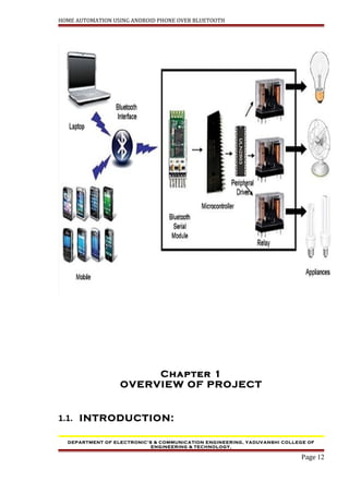
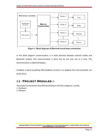
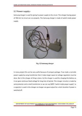
This project report details a home automation system utilizing Bluetooth technology and an Android phone, aimed at simplifying control of various appliances within the home. The system employs an Atmel AT89S52 microcontroller to manage connections and commands sent from a mobile device, enabling automated control of devices like lights and fans wirelessly. The project serves as a practical application for electronics and communication engineering students at Yaduvanshi College, fulfilling degree requirements for the Bachelor of Technology program.


![HOME AUTOMATION USING ANDROID PHONE OVER BLUETOOTH
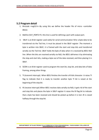
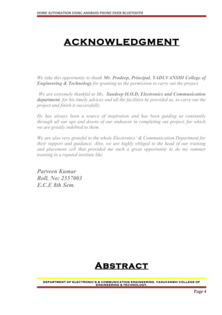
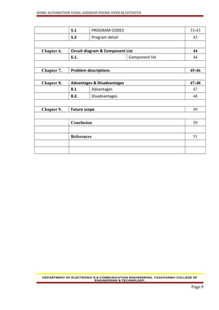
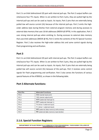
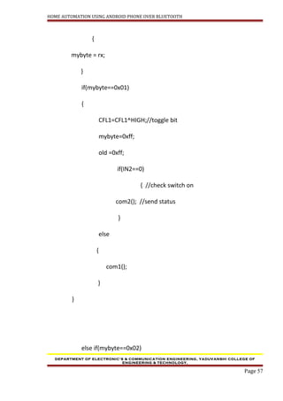
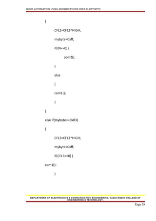
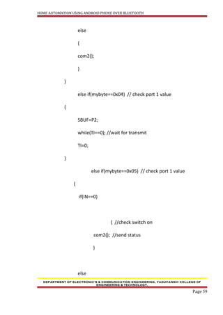
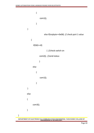
5.1 PROGRAM CODES:
#include <reg52.h>
#define OUT_PORT1 P2
#define HIGH 1
sbit IN = P2^0;
sbit IN2 = P2^1;
sbit CFL1 = OUT_PORT1^5;
sbit CFL2 = OUT_PORT1^6;
sbit CFL3 = OUT_PORT1^7;
void com3();
void com2();
void com1();
void delay(const unsigned int ms);
unsigned char z;
unsigned char Mess1[]="SW OFF,";
unsigned char Mess2[]="SW ONN,";
unsigned char Mess3[]="Access Denied,";
void main()
DEPARTMENT OF ELECTRONIC’S & COMMUNICATION ENGINEERING, YADUVANSHI COLLEGE OF
ENGINEERING & TECHNOLOGY,
Page 55](https://image.slidesharecdn.com/projectreporthomeautomation-150623025102-lva1-app6892/85/HOME-AUTOMATION-USING-ANDROID-PHONE-OVER-BLUETOOTH-55-320.jpg)
![HOME AUTOMATION USING ANDROID PHONE OVER BLUETOOTH
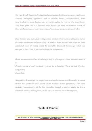
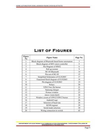
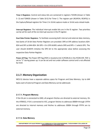
}
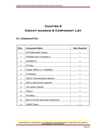
void com3()
{
for (z=0;z<15;z++) {
SBUF=Mess3[z]; //place value in buffer
while(TI==0); //wait for transmit
TI=0;
}
}
void com2()
{
for (z=0;z<8;z++) {
SBUF=Mess2[z]; //place value in buffer
while(TI==0); //wait for transmit
TI=0;
}
DEPARTMENT OF ELECTRONIC’S & COMMUNICATION ENGINEERING, YADUVANSHI COLLEGE OF
ENGINEERING & TECHNOLOGY,
Page 61](https://image.slidesharecdn.com/projectreporthomeautomation-150623025102-lva1-app6892/85/HOME-AUTOMATION-USING-ANDROID-PHONE-OVER-BLUETOOTH-61-320.jpg)
![HOME AUTOMATION USING ANDROID PHONE OVER BLUETOOTH
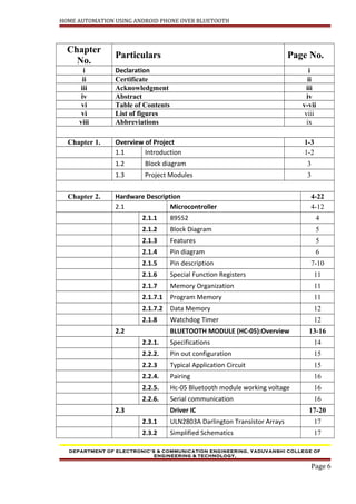
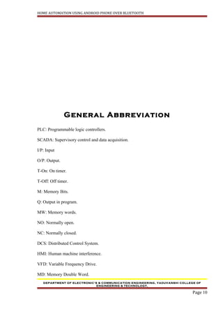
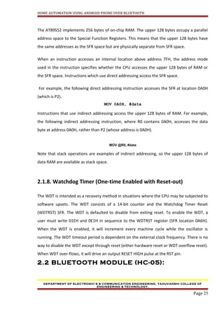
}
void com1()
{
for (z=0;z<8;z++) {
SBUF=Mess1[z]; //place value in buffer
while(TI==0); //wait for transmit
TI=0;
}
}
void delay(const unsigned int ms)
{
unsigned int x, y;
for(x = 0; x<=ms;x++)
{
for(y=0;y<=1275;y++);
}
}
DEPARTMENT OF ELECTRONIC’S & COMMUNICATION ENGINEERING, YADUVANSHI COLLEGE OF
ENGINEERING & TECHNOLOGY,
Page 62](https://image.slidesharecdn.com/projectreporthomeautomation-150623025102-lva1-app6892/85/HOME-AUTOMATION-USING-ANDROID-PHONE-OVER-BLUETOOTH-62-320.jpg)