Download to read offline

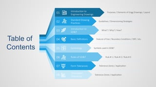
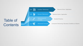
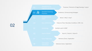
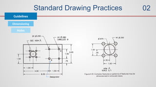
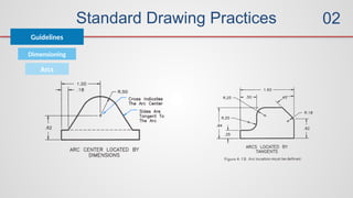
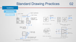
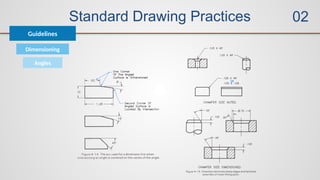
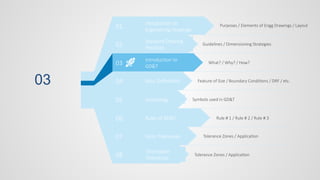
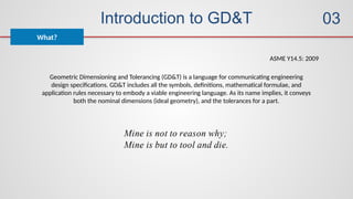
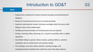
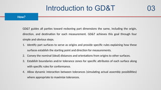
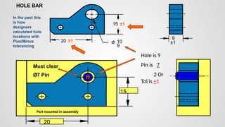
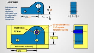
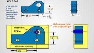

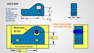
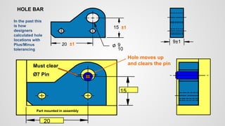


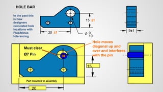
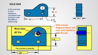
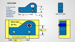
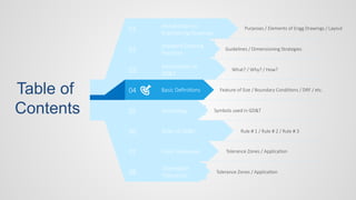
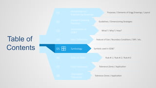
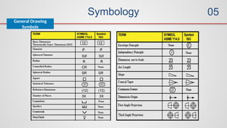
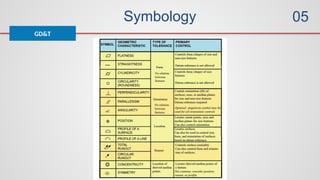
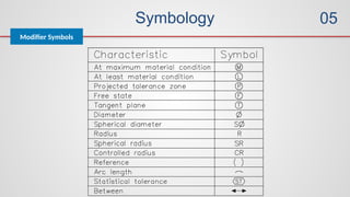
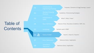
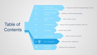
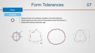
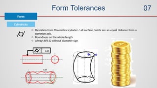
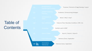
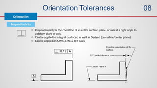
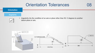
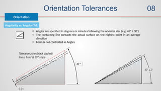
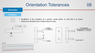
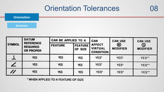


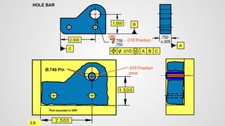
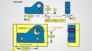


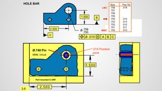


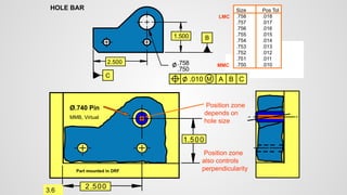


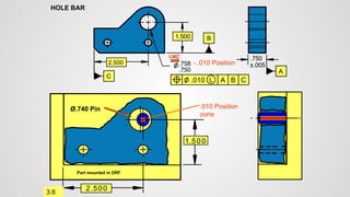
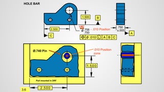


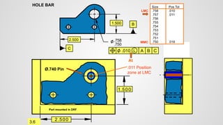
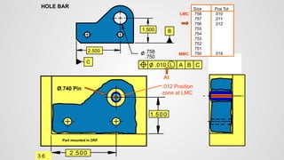


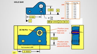


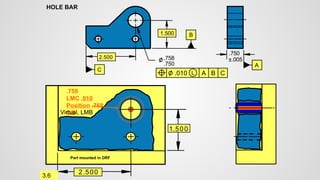


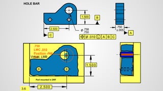


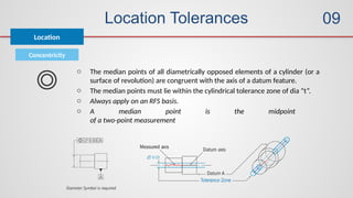
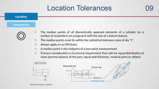
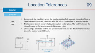
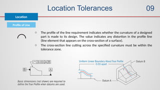
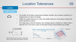
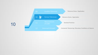
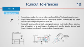
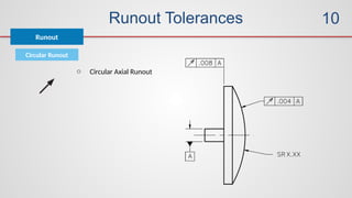
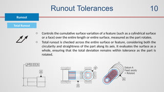
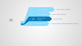
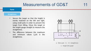
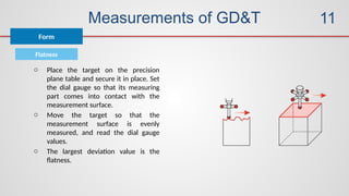


The presentation is about the why of GD&T and the basics of GD&T from a complete beginner to a moderate level where you can understand the calculations of tolerance zones and basics of datums. It explains Feature of Size / Boundary Conditions / DRF / etc, Symbols used in GD&T, Rule # 1 / Rule # 2 / Rule # 3, Tolerance Zones / Application, Standard Practices, Measurement Methods, Composite Tolerancing / Boundary Conditions on Datums, Form tolerances, Orientation tolerances, location tolerances, Runout tolerances. etc, Rules of GD&T, ISO 1101, ISO 5691, BS 8888. Various standards are used to elaborate the concepts.


