The document outlines methods and equipment for distance measurement in geomatics, including pacing, taping, and electronic distance measurement (EDM). It details taping procedures, systematic and random errors, the principles of EDM, and the use of total station instruments in surveying. Additionally, it discusses factors affecting accuracy, such as temperature, tension, and atmospheric conditions.

![• Improper plumbing.
• Faulty marking.
• Incorrect reading or interpolation.
7
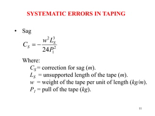
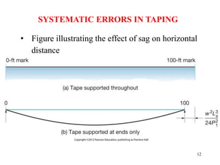
RANDOM ERRORS IN TAPING
[Should corrections be added or subtracted?]](https://image.slidesharecdn.com/chapter06-measuringdistance-240715064708-2c2c7fb3/85/BASIC-SURVEYING-Measuring_Distance-pptx-7-320.jpg)

![EXAMPLE 6.1
A 30-m steel tape (k = 0.0000116; E = 2,000,000 kg/cm2) was standardized at
20 C° and supported throughout under a tension of 5.45 kg and it was found to
be 30.012 m long. The tape had a cross-sectional area of 0.05 cm2 and a weight
of 0.03967 kg/m. That tape was held horizontal, supported at the ends only,
with a constant tension of 9.09 kg, to measure a line from A to B in three
segments as per the recorded data shown below. Apply corrections for tape
length, temperature, pull, and sag and determine the correct length of the line
(answer: 81.131 m).
Section Measured Distance Temperature (C°)
A-1 30.000 14
1-2 30.000 15
2-B 21.151 16
[Solution next page]
15
COMBINED CORRECTIONS IN TAPING](https://image.slidesharecdn.com/chapter06-measuringdistance-240715064708-2c2c7fb3/85/BASIC-SURVEYING-Measuring_Distance-pptx-15-320.jpg)

![Example 6.2
A 100 ft tape standardized at 68oF and supported throughout
under a tension of 20 lb was found to be 100.012 ft long. The
tape had a cross-sectional area of 0.0078 in.2 and a weight of
0.0266 lb/ft. This tape is used to lay off a horizontal distance CD
of exactly 175.00 ft. The ground is on a smooth 3% grade, thus
the tape will be used fully supported. Determine the correct slope
distance to layoff if a pull of 15 lb is used and temperature is
87oF.
[Solution next page]
17
COMBINED CORRECTIONS IN TAPING](https://image.slidesharecdn.com/chapter06-measuringdistance-240715064708-2c2c7fb3/85/BASIC-SURVEYING-Measuring_Distance-pptx-17-320.jpg)


![21
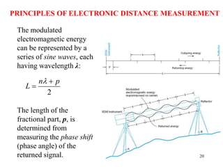
PRINCIPLES OF ELECTRONIC DISTANCE MEASUREMENT
Example
If the number of cycles is 9, wavelength is 20 m and the
phase angle of the returned signal is 115.7°, calculate the
length of the fractional part and the overall measured
length (answer: 93.214 m).
[See Whiteboard]](https://image.slidesharecdn.com/chapter06-measuringdistance-240715064708-2c2c7fb3/85/BASIC-SURVEYING-Measuring_Distance-pptx-21-320.jpg)


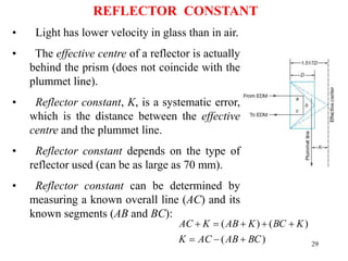
![26
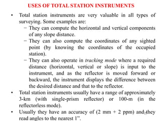
USING TOTAL STATIONS TO COMPUTE HORIZONTAL
LENGTHS FROM SLOPE DISTANCES
)
(
)
( r
B
e
A h
elev
h
elev
d
Example
A slope distance of 165.360 m was measured from A to B, whose
elevations were 447.401 and 445.389 m above datum, respectively.
Find the horizontal length of line AB if the height of the total
station and the reflector were 1.417 and 1.615 m above their
respective stations (answer: 165.350 m).
[See whiteboard]](https://image.slidesharecdn.com/chapter06-measuringdistance-240715064708-2c2c7fb3/85/BASIC-SURVEYING-Measuring_Distance-pptx-26-320.jpg)
![28
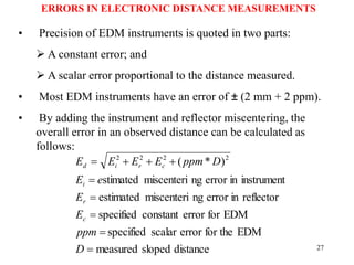
ERRORS IN ELECTRONIC DISTANCE MEASUREMENTS
Example
A slope distance of 827.329 m was measured between two stations
with an EDM instrument that has an error of ± (2 mm + 2 ppm). the
instrument was centered with an estimated error of ± 3 mm, and the
reflector was centered with an estimated error of ± 5 mm. Calculate
the overall estimated error in the measured distance and its
precision (answer: ± 6.4 mm, 1:129,000).
[See whiteboard]](https://image.slidesharecdn.com/chapter06-measuringdistance-240715064708-2c2c7fb3/85/BASIC-SURVEYING-Measuring_Distance-pptx-28-320.jpg)