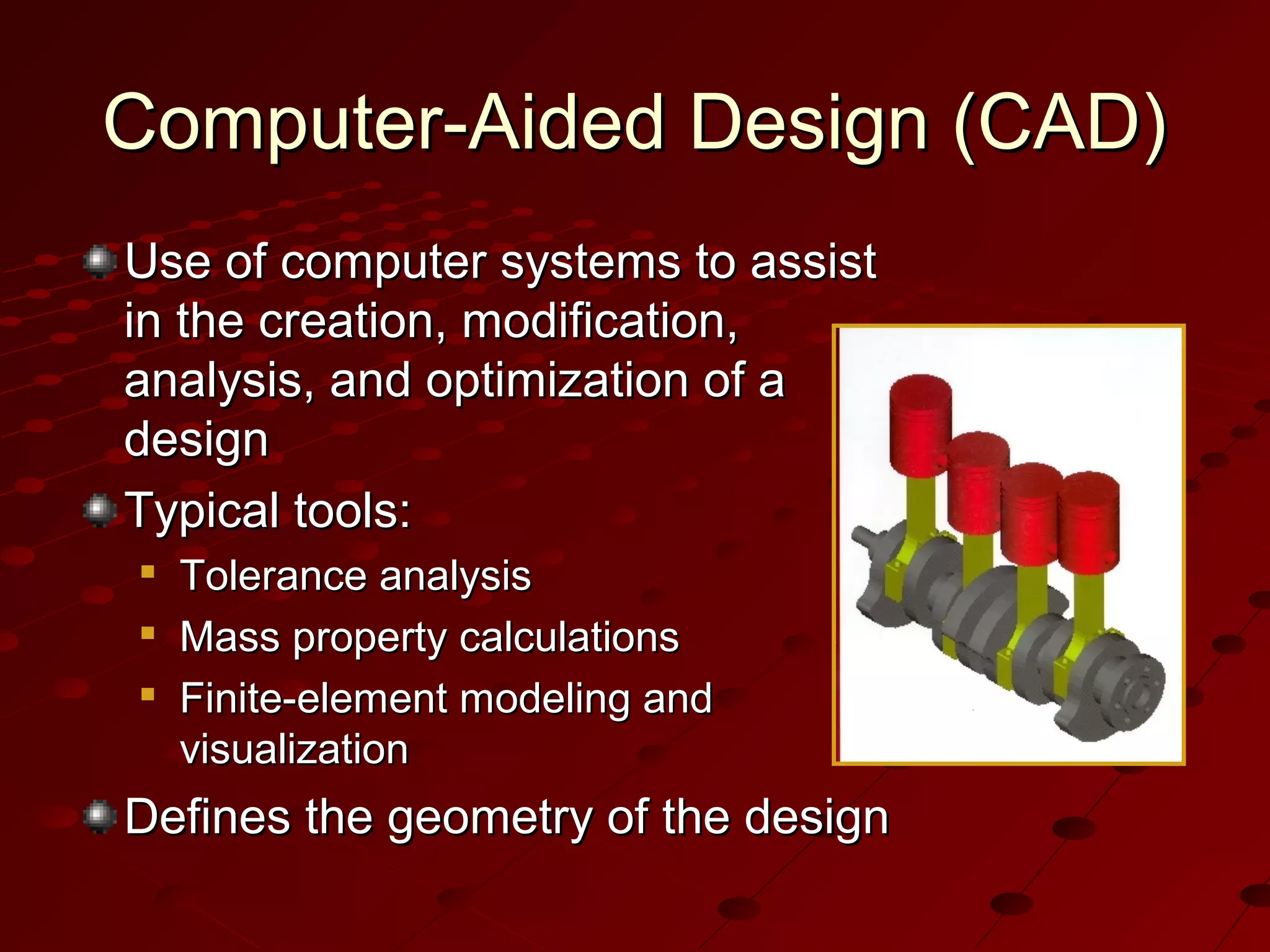
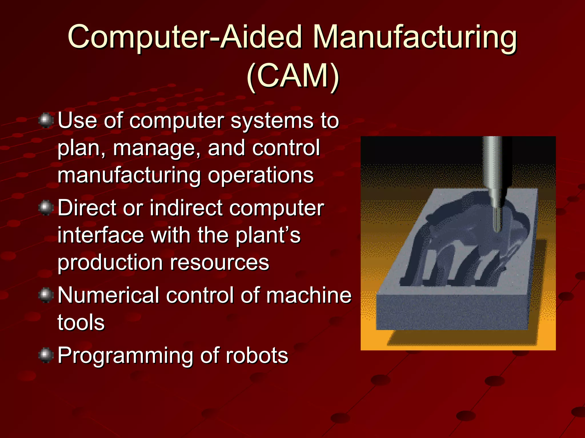
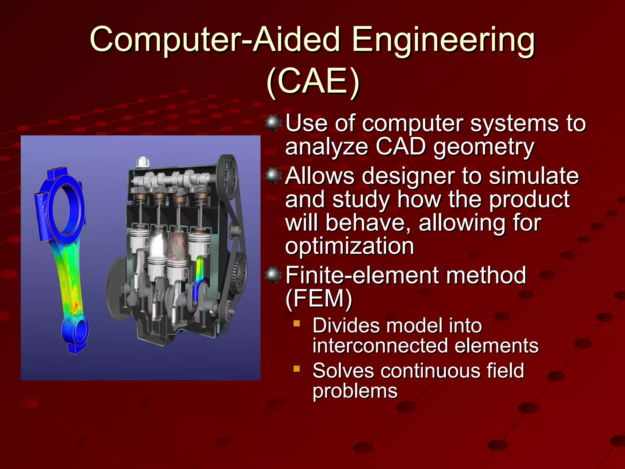
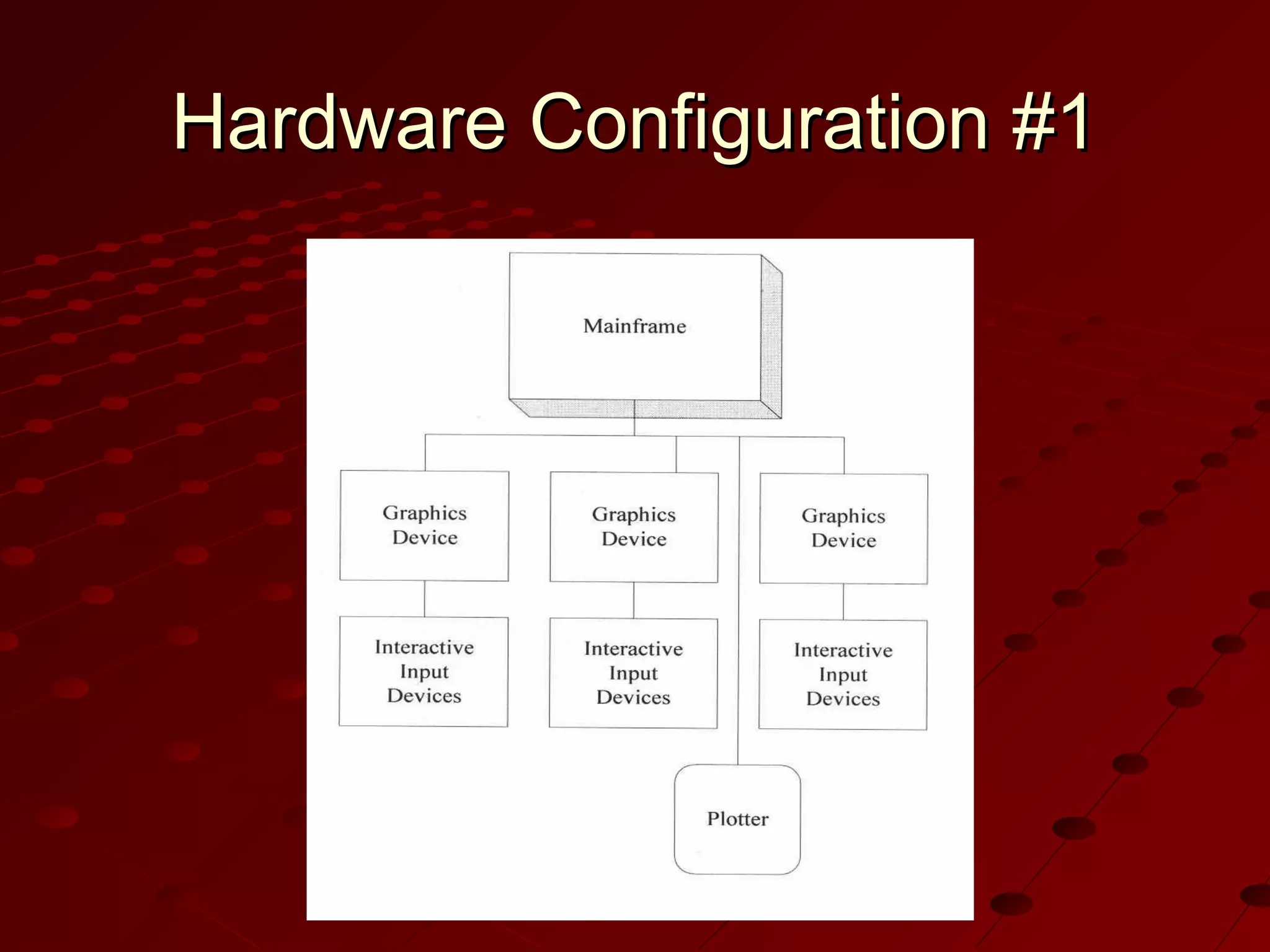
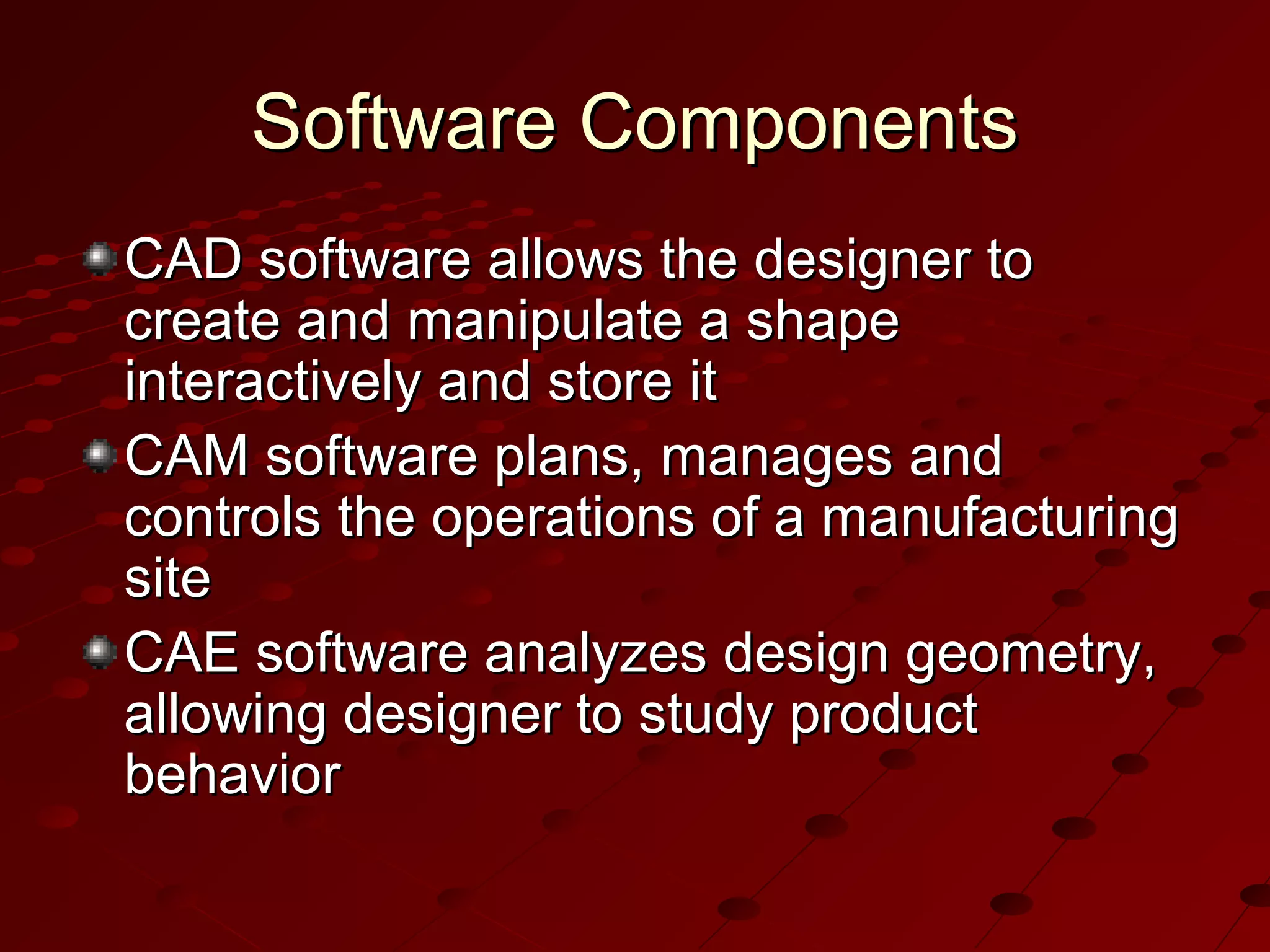
Computer-Aided Design
Computer-Aided Design (CAD)
Use of computer systems to assist
in the creation, modification,
analysis, and optimization of a
design
Typical tools:




Tolerance analysis
Mass property calculations
Finite-element modeling and
visualization

Defines the geometry of the design
Computer-Aided Manufacturing
(CAM)
Use of computer systems to
plan, manage, and control
manufacturing operations
Direct or indirect computer
interface with the plant’s
production resources
Numerical control of machine
tools
Programming of robots
Computer-Aided Engineering
(CAE)
Use of computer systems to
analyze CAD geometry
Allows designer to simulate
and study how the product
will behave, allowing for
optimization
Finite-element method
(FEM)




Divides model into
interconnected elements
Solves continuous field
problems
Computer-Aided Design Process
Two types of activities: synthesis and
analysis
Synthesis is largely qualitative and hard to
capture on computer
Analysis can be greatly enhanced with
computers
Once analysis is complete, design
evaluation- rapid prototyping
Software packages for design optimization
Components of CAD Systems
Major component is hardware
and software allowing shape
manipulation
Hardware includes graphic
devices and their peripherals
for input and output
operations
Software includes packages
that manipulate or analyze
shapes according to user
interaction
Components of CAD Systems
Hardware Components
Graphic device is composed of a display
processing unit, a display device, and one or
more input devices
Input devices:





Mouse
Space ball
Data tablet with a puck or stylus
Keyboard

Output Devices:



Plotters
Color laser printers
Hardware Configuration #1
Requires a big initial
investment for
hardware and software

Maintenance of
mainframe is
expensive

Slow system response
times

Updating operating
systems is difficult
Hardware Configuration #2
Engineering
workstations connected
in a networked
environment

User can choose
appropriate
workstation on a task
by task basis

Widely used; trend
toward distributed
computing

Initial investment is
smaller than
configuration #1
Hardware Configuration #3
Popular with
small companies

Popular with companies
whose main purpose is
to generate drawings
with their
CAD/CAM/CAE systems

Same as the second,
except engineering
workstations are replaced
by personal computers
running Microsoft Windows
Distinction between
configurations 2 and 3
becoming blurred as
personal computers
evolve
Software Components
CAD software allows the designer to
create and manipulate a shape
interactively and store it
CAM software plans, manages and
controls the operations of a manufacturing
site
CAE software analyzes design geometry,
allowing designer to study product
behavior
Windows-Based CAD Systems
User interface is similar to Windows
Employs component technology, in which
best key software elements are selected
from among available software
Use object-oriented technology, which
modularizes the program
Capable of either parametric or variational
modeling
Internet support
Rapid Prototyping
Layer by layer fabrication of
three-dimensional physical
models from CAD
Fast and inexpensive
alternative for producing
prototypes and functional
models
Rapid Prototyping has surgical applications
Build parts in thin layers
Minimum operation time;
typically runs unattended
Medical Modeling - Zcorp
Rapid Prototyping Cycle
.STL is standard file format
for all U.S. rapid
prototyping systems
Preprocessing prepares
.STL file for various rapid
prototyping systems
Build process can last
from a few hours to
several days
Post processing: removal
of part from machine,
support removal, sanding
Rapid Prototyping Process
“A computer-controlled laser beam
is scanned across the surface of a
vat of liquid photopolymer,
instantly solidifying the liquid at
each point of contact. Using data
generated from a CAD file,
individual cross-sections of the
three-dimensional geometry are
solidified in turn to build up a solid
part layer by layer. In this way
even highly complex geometries
can be built in a few hours without
requiring any tools. “
Thank you

Cad

  • 1.
  • 3.
    Computer-Aided Design (CAD) Useof computer systems to assist in the creation, modification, analysis, and optimization of a design Typical tools:    Tolerance analysis Mass property calculations Finite-element modeling and visualization Defines the geometry of the design
  • 4.
    Computer-Aided Manufacturing (CAM) Use ofcomputer systems to plan, manage, and control manufacturing operations Direct or indirect computer interface with the plant’s production resources Numerical control of machine tools Programming of robots
  • 5.
    Computer-Aided Engineering (CAE) Use ofcomputer systems to analyze CAD geometry Allows designer to simulate and study how the product will behave, allowing for optimization Finite-element method (FEM)   Divides model into interconnected elements Solves continuous field problems
  • 6.
    Computer-Aided Design Process Twotypes of activities: synthesis and analysis Synthesis is largely qualitative and hard to capture on computer Analysis can be greatly enhanced with computers Once analysis is complete, design evaluation- rapid prototyping Software packages for design optimization
  • 7.
    Components of CADSystems Major component is hardware and software allowing shape manipulation Hardware includes graphic devices and their peripherals for input and output operations Software includes packages that manipulate or analyze shapes according to user interaction
  • 8.
  • 9.
    Hardware Components Graphic deviceis composed of a display processing unit, a display device, and one or more input devices Input devices:     Mouse Space ball Data tablet with a puck or stylus Keyboard Output Devices:   Plotters Color laser printers
  • 10.
  • 11.
    Hardware Configuration #1 Requiresa big initial investment for hardware and software Maintenance of mainframe is expensive Slow system response times Updating operating systems is difficult
  • 12.
  • 13.
    Hardware Configuration #2 Engineering workstationsconnected in a networked environment User can choose appropriate workstation on a task by task basis Widely used; trend toward distributed computing Initial investment is smaller than configuration #1
  • 14.
    Hardware Configuration #3 Popularwith small companies Popular with companies whose main purpose is to generate drawings with their CAD/CAM/CAE systems Same as the second, except engineering workstations are replaced by personal computers running Microsoft Windows Distinction between configurations 2 and 3 becoming blurred as personal computers evolve
  • 15.
    Software Components CAD softwareallows the designer to create and manipulate a shape interactively and store it CAM software plans, manages and controls the operations of a manufacturing site CAE software analyzes design geometry, allowing designer to study product behavior
  • 16.
    Windows-Based CAD Systems Userinterface is similar to Windows Employs component technology, in which best key software elements are selected from among available software Use object-oriented technology, which modularizes the program Capable of either parametric or variational modeling Internet support
  • 17.
    Rapid Prototyping Layer bylayer fabrication of three-dimensional physical models from CAD Fast and inexpensive alternative for producing prototypes and functional models Rapid Prototyping has surgical applications Build parts in thin layers Minimum operation time; typically runs unattended
  • 18.
  • 19.
  • 20.
    Rapid Prototyping Cycle .STLis standard file format for all U.S. rapid prototyping systems Preprocessing prepares .STL file for various rapid prototyping systems Build process can last from a few hours to several days Post processing: removal of part from machine, support removal, sanding
  • 21.
    Rapid Prototyping Process “Acomputer-controlled laser beam is scanned across the surface of a vat of liquid photopolymer, instantly solidifying the liquid at each point of contact. Using data generated from a CAD file, individual cross-sections of the three-dimensional geometry are solidified in turn to build up a solid part layer by layer. In this way even highly complex geometries can be built in a few hours without requiring any tools. “
  • 22.

Editor's Notes

  • #2 Original author: Paul King Presentation modified by: Karen Schuyler
  • #4 Picture from: http://www.engr.uconn.edu/~ewebhk/buttons/cad/cad.jpg
  • #5 Image from: http://www.nvision3d.com/images/toolpath%5B1%5D.gif
  • #6 Image from: www.sgi.com/fun/gallery/ images/cae.jpg
  • #8 Image from: http://www.dal.ca/~rwarner/images/cae.gif
  • #10 Mouse from: http://www.demonatthus.net/focus/images/mouse.jpg Keyboard from: www.igmdesign.com/studio/ 4/phonedata/keyboard.jpg Plotter from: thenew.hp.com/.../eng/prodserv/ printing_multifunction.html
  • #18 Image from : http://www.engr.ncsu.edu/news/news_articles/harrysson.html
  • #19 Picture from: http://www.zcorp.com/industries/spotlight.asp?ID=12
  • #21 Image from: www.dal.ca/~rwarner/amg.htm
  • #22 Picture and text from: http://www.damvig.com/english/index.htm