COMPUTER AIDED DESIGN(CAD)
UNIT – I Fundamentals of Computer
Graphics
Presented by
Engr OCHERI C
CAD
CAD also known as Computer Aided
Drafting/Design.
There are 3 different types of CAD (2D,
2.5D and 3D).
The software is used to create and design
models of these types and test them.
3.
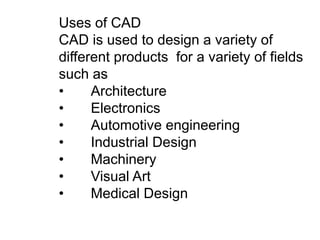
Uses of CAD
CADis used to design a variety of
different products for a variety of fields
such as
• Architecture
• Electronics
• Automotive engineering
• Industrial Design
• Machinery
• Visual Art
• Medical Design
4.
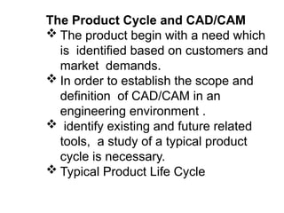
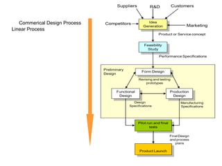
The Product Cycleand CAD/CAM
The product begin with a need which
is identified based on customers and
market demands.
In order to establish the scope and
definition of CAD/CAM in an
engineering environment .
identify existing and future related
tools, a study of a typical product
cycle is necessary.
Typical Product Life Cycle
6.
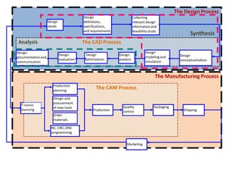
•Inspection to finishedproduct
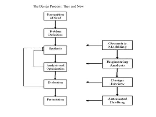
•Two main process
•Design Process
» Synthesis
(Sketches, Layout drawings- CAD/CAM
system)
» Analysis
(Design Modeling & Simulation)
–Manufacturing Process
–(Process Planning & Production)
(Outcome Production Plan, tools
procurement, material order, CNC
–Programming)
7.
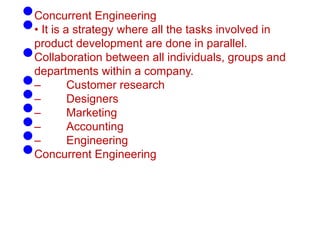
•Concurrent Engineering
•• Itis a strategy where all the tasks involved in
product development are done in parallel.
•Collaboration between all individuals, groups and
departments within a company.
•– Customer research
•– Designers
•– Marketing
•– Accounting
•– Engineering
•Concurrent Engineering
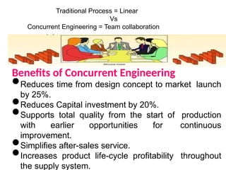
Traditional Process =Linear
Vs
Concurrent Engineering = Team collaboration
Benefits of Concurrent Engineering
•Reduces time from design concept to market launch
by 25%.
•Reduces Capital investment by 20%.
•Supports total quality from the start of production
with earlier opportunities for continuous
improvement.
•Simplifies after-sales service.
•Increases product life-cycle profitability throughout
the supply system.
Before CADAfter CAD
CAD/CAMSystems
1.Hardware
2.Software
üGUI
üClient/Standalone
üDatabase
üWorks on all OS [ Unix,Linux,Windows,Macintosh]
CAD/CAM Applications
•Geometric Module
•Application Module
•Programming Module
Modelling/editing,
documentation
Utilize model for Design
Analysis.
Customization by
programming
• Communication Module à IGES, STEP file
• Collaborative Module à collaborative design via internet
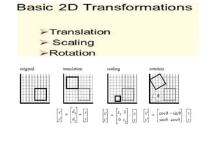
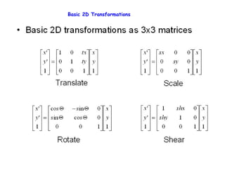
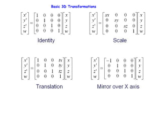
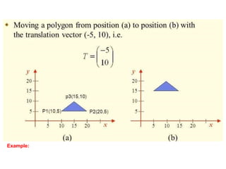
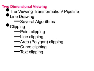
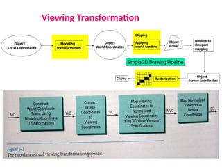
2D Transformations
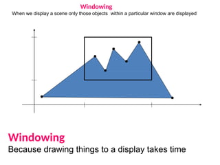
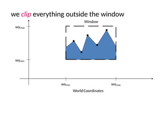
Windowing
When we displaya scene only those objects within a particular window are displayed
Windowing
Because drawing things to a display takes time
20.
we clip everythingoutside the window
wymax
wymin
wxmin wxmax
WorldCoordinates
Window
21.
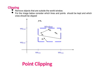
Clipping
• Remove objectsthat are outside the world window.
• For the image below consider which lines and points should be kept and which
ones should be clipped
Point Clipping
wymax
wymin
wxmin wxmax
Window
P1
P6
P5
P3
P7
P10
P9
P4
P2
P8

![Before CADAfter CAD
CAD/CAM Systems
1.Hardware
2.Software
üGUI
üClient/Standalone
üDatabase
üWorks on all OS [ Unix,Linux,Windows,Macintosh]
CAD/CAM Applications
•Geometric Module
•Application Module
•Programming Module
Modelling/editing,
documentation
Utilize model for Design
Analysis.
Customization by
programming
• Communication Module à IGES, STEP file
• Collaborative Module à collaborative design via internet
2D Transformations](https://image.slidesharecdn.com/bme544lecturenote1cad-251005141857-eb31cb99/85/BME-544-Lecture-Note-1-for-500-Level-CAD-pptx-11-320.jpg)