- Transmission line faults are mainly transient faults caused by lightning or persistent faults from downed lines.
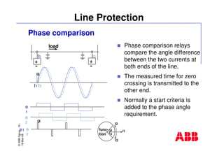
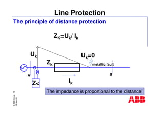
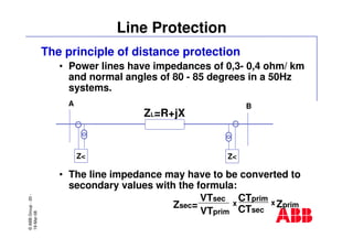
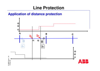
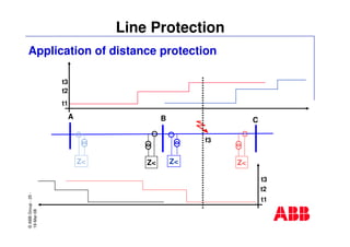
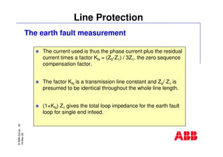
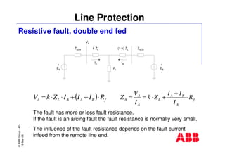
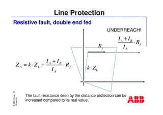
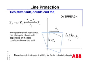
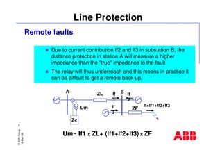
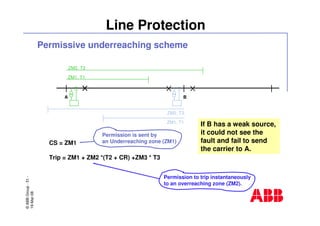
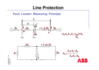
- Distance protection relies on measuring the impedance between the relay and the fault to determine the fault location and operate selectively.
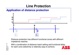
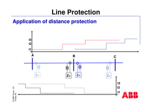
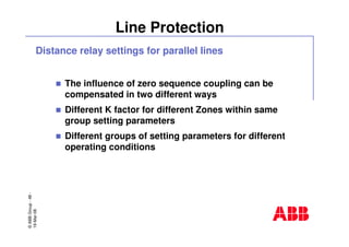
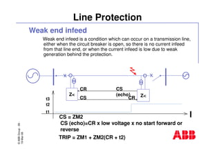
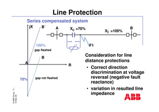
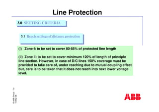
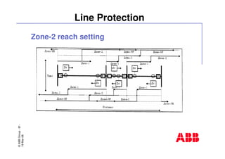
- Distance relays divide the line into zones and use different impedance thresholds and time delays for each zone to coordinate with protection on adjacent line sections.
![©ABBGroup-8-
19-Mar-08
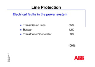
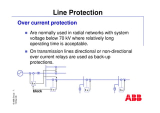
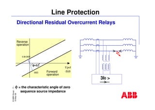
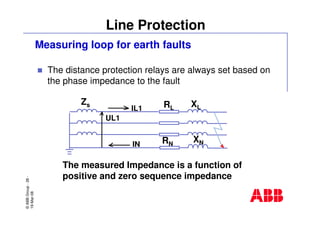
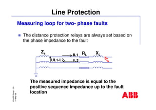
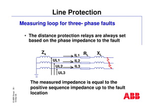
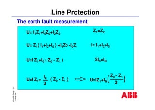
Line Protection
Dependent Time Overcurrent Relays
CHARACTERISTICS OF
DEPENDENT TIME OVERCURRENT RELAYS
0.1
1.0
10.0
100.0
1 10 100
Current (multiple of setting)
OperateTime[s]
Long Time Inverse
Extremely Inverse
Normal Inverse
Very Inverse](https://image.slidesharecdn.com/lineprotectionbasics-june2008-150422025540-conversion-gate02/85/Lineprotection-basics-june2008-8-320.jpg)


![protection of transmission lines[distance relay protection scheme]](https://cdn.slidesharecdn.com/ss_thumbnails/os-exe3-23-may2011-sr-i-776s21tr-lineprotection-120425095503-phpapp02-thumbnail.jpg?width=640&height=640&fit=bounds)