Download as PDF, PPTX
![Definitions
EXPOSED-CONDUCTIVE-PART
conductive part of equipment which
can be touched and which is not
normally live, but which can become
live when basic insulation fails
[IEV 195-06-10]](https://image.slidesharecdn.com/earthingandbonding-190616163015/85/Earthing-and-bonding-Power-cables-5-320.jpg)
![Definitions
PROTECTIVE CONDUCTOR
conductor provided for
purposes of safety, for
example protection against
electric shock
[IEV 195-02-09]](https://image.slidesharecdn.com/earthingandbonding-190616163015/85/Earthing-and-bonding-Power-cables-6-320.jpg)
![Definitions
MAIN EARTHING TERMINAL
(main earthing busbar)
terminal or busbar which is part
of the earthing arrangement of
an installation enabling the
electric connection of a number
of conductors for earthing
purposes
[IEV 195-02-33]](https://image.slidesharecdn.com/earthingandbonding-190616163015/85/Earthing-and-bonding-Power-cables-7-320.jpg)
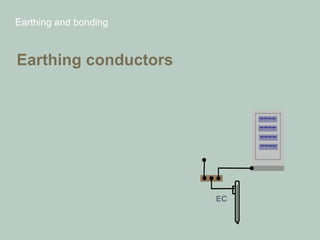
![Definitions
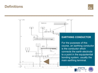
EARTHING CONDUCTOR
conductor which provides a
conductive path, or part of the
conductive path, between a
given point in a system or in
an installation or in equipment
and an earth electrode
[IEV 195-02-03]](https://image.slidesharecdn.com/earthingandbonding-190616163015/85/Earthing-and-bonding-Power-cables-8-320.jpg)
![Definitions
EARTH ELECTRODE
conductive part, which may be
embedded in a specific
conductive medium, e.g.
concrete, in electric contact
with the earth
[IEV 195-02-01]](https://image.slidesharecdn.com/earthingandbonding-190616163015/85/Earthing-and-bonding-Power-cables-10-320.jpg)
![Definitions
EXTRANEOUS-
CONDUCTIVE-PART
conductive part not forming
part of the electrical
installation and liable to
introduce an electric potential,
generally the electric potential
of a local earth
[IEV 195-06-11]](https://image.slidesharecdn.com/earthingandbonding-190616163015/85/Earthing-and-bonding-Power-cables-11-320.jpg)
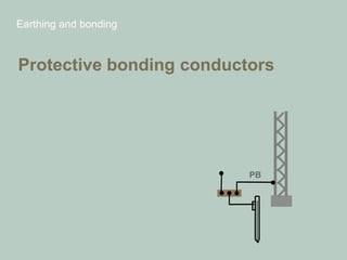
![Definitions
PROTECTIVE BONDING
CONDUCTOR
protective conductor provided
for protective-equipotential-
bonding
[IEV 195-02-10]](https://image.slidesharecdn.com/earthingandbonding-190616163015/85/Earthing-and-bonding-Power-cables-12-320.jpg)
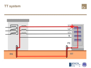
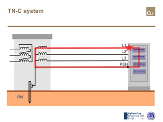
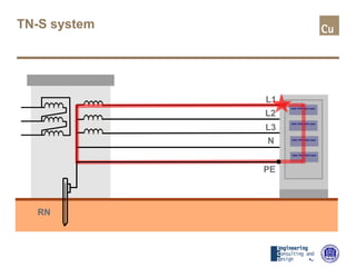
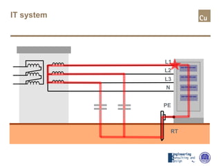
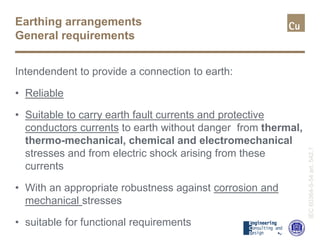
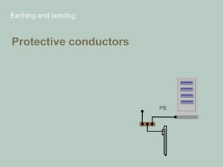
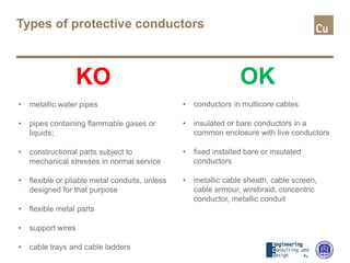
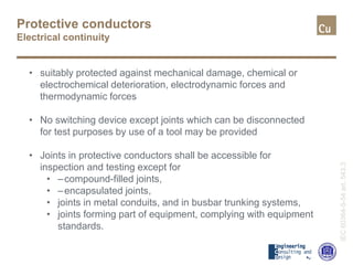
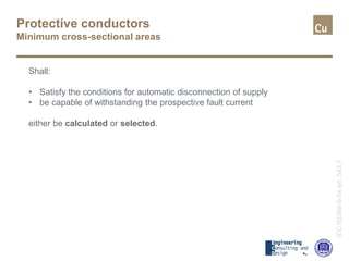
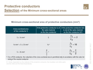
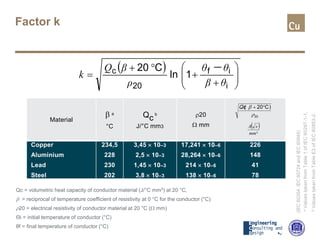
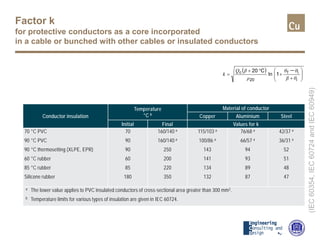
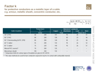
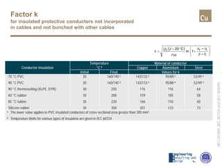
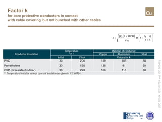
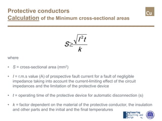
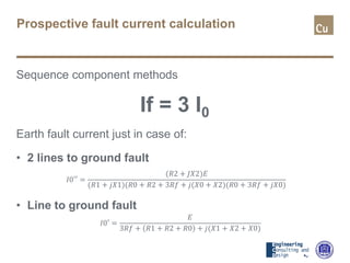
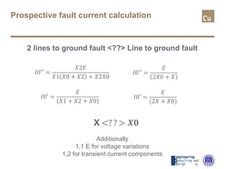
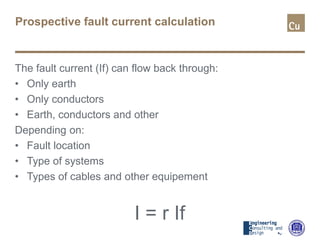
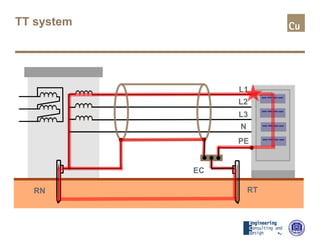
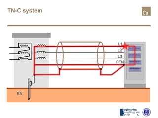
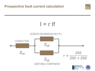
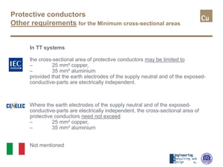
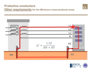
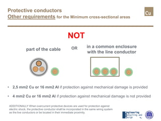
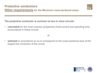
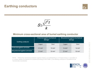
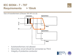


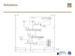
This document discusses earthing and bonding. It defines key terms like protective conductor, earthing conductor, and equipotential bonding. It describes different electrical system types like TT, TN-C, TN-S, and IT. It discusses general requirements for earthing arrangements and protective conductors. Protective conductors must provide reliable connection to earth and be suitably protected. Minimum cross-sectional areas for protective conductors depend on line conductor size and prospective fault current calculation factors. The document provides factors and formulas for calculating prospective fault current and sizing protective conductors accordingly.


![5G Explained! A High Level Overview [Introduction]](https://cdn.slidesharecdn.com/ss_thumbnails/5gexplainedahighleveloverview-260119165306-cc137a3e-thumbnail.jpg?width=640&height=640&fit=bounds)


