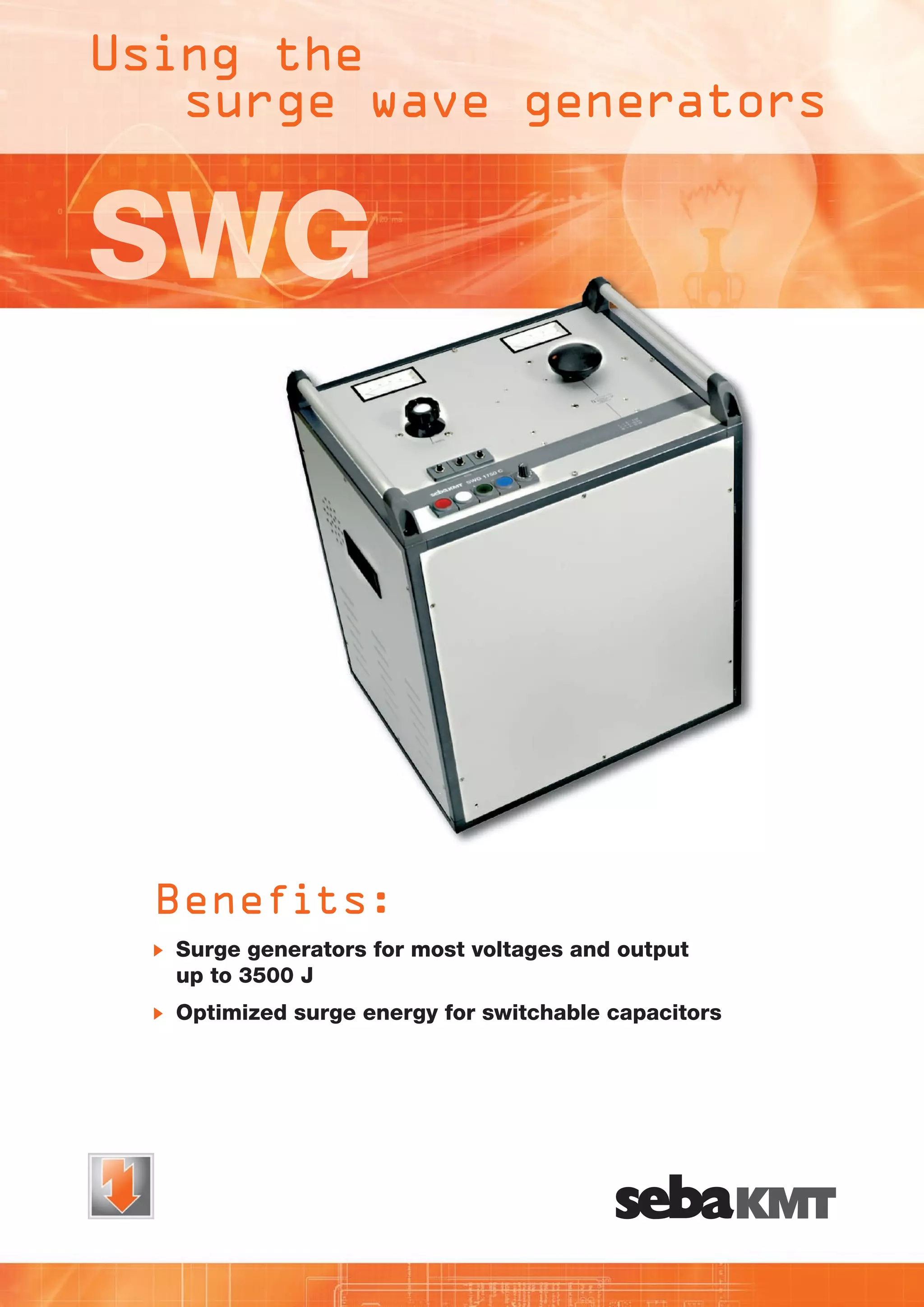
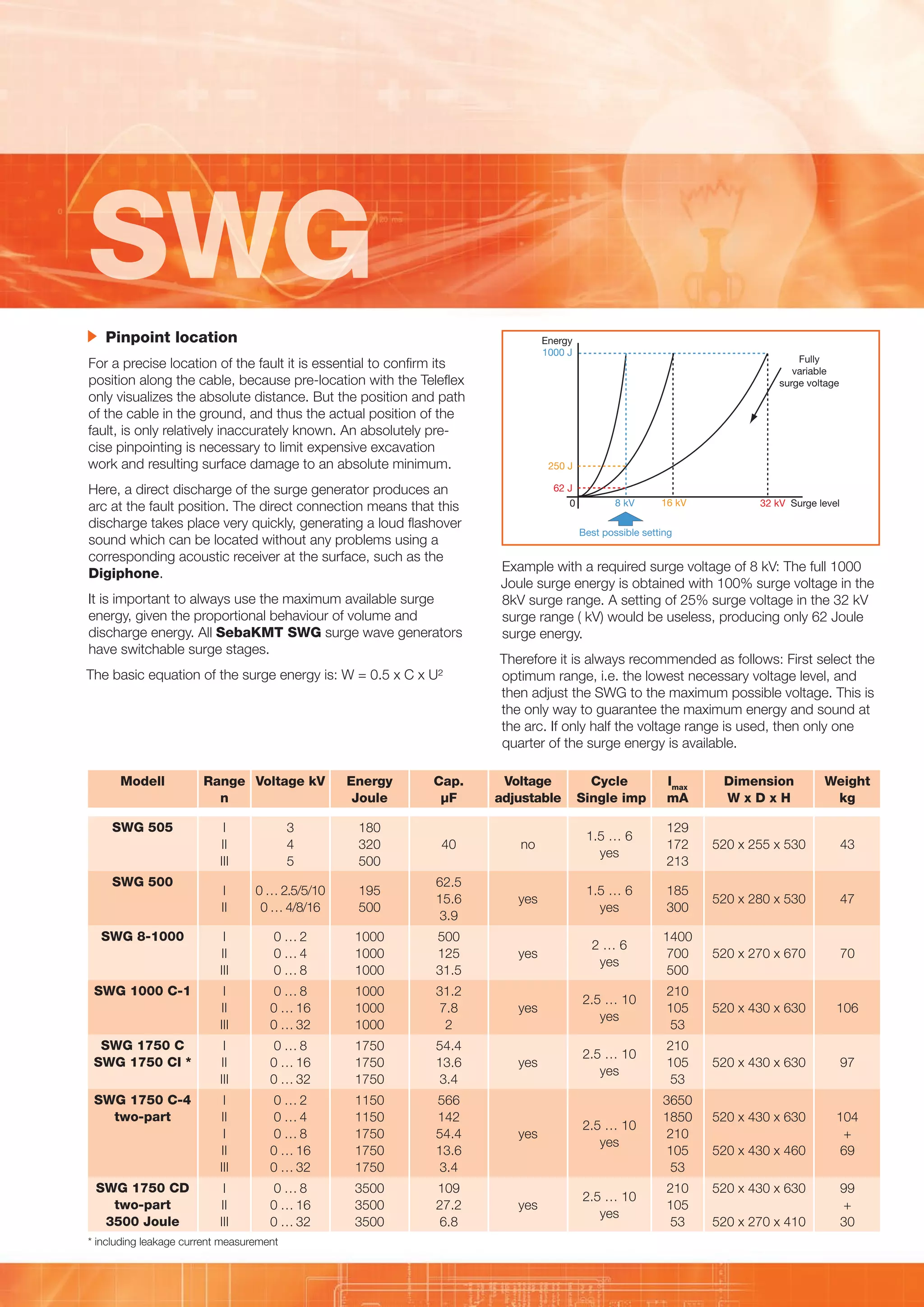
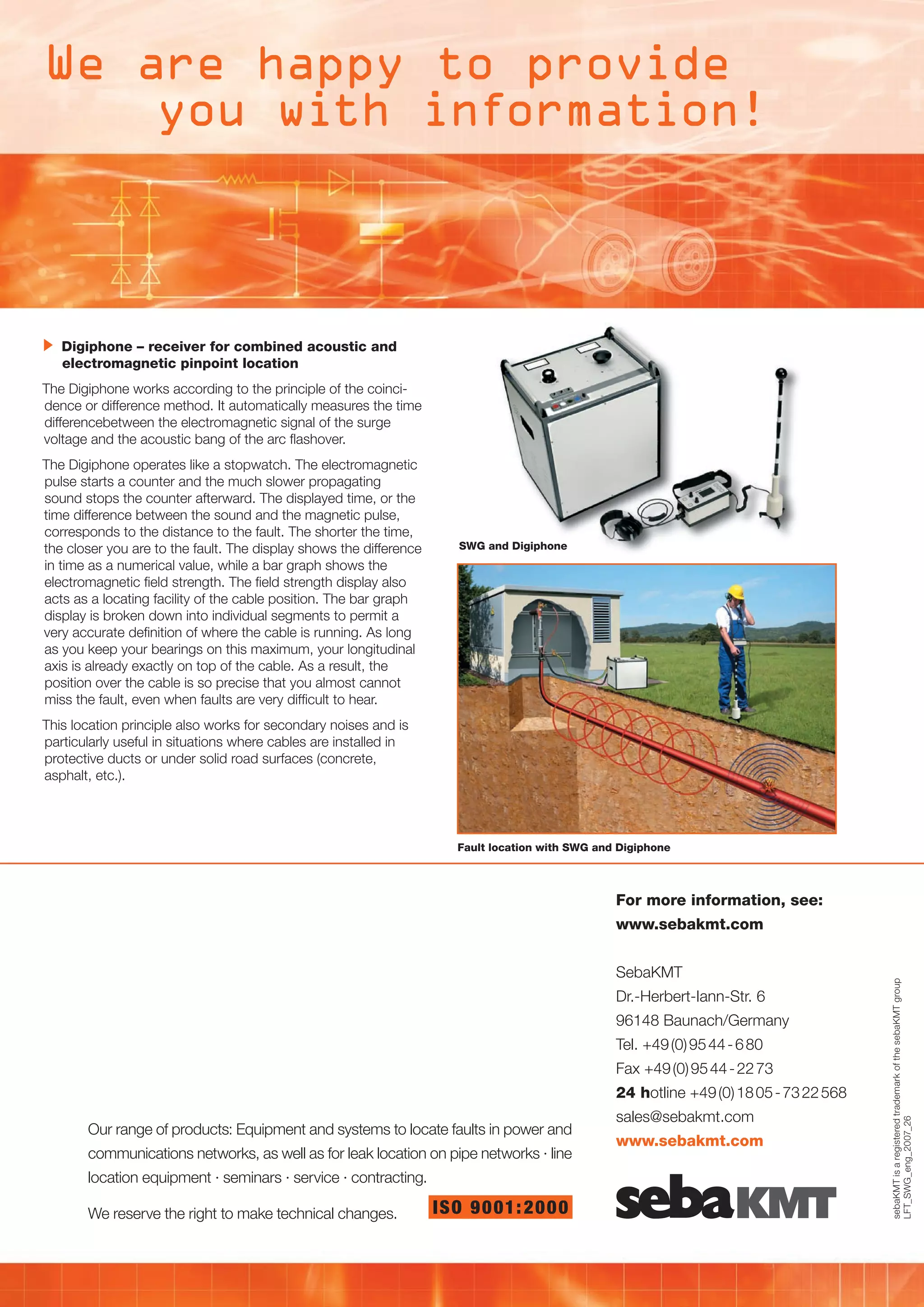
Using the
surge wave generators

SWG

Benefits:
	 Surge	generators	for	most	voltages	and	output	
up	to	3500	J
	 Optimized	surge	energy	for	switchable	capacitors
Using the
surge wave generators

Together with reflectometers, surge generators are the central
component for cable fault location. They are used for both prelocation and also pinpoint location.

	 Prelocation
Prelocation can be divided into transient methods and Arc
reflection prelocation, which differentiates between passive,
semi-active and active methods.
ICE – Impulse Current Method 	
(ICE-Method = Impulse Current Equipment)
This method is ideal particularly for fault location in long ground
cables and wet splices.
The surge wave generator ignites an arc at the fault. This
results in a transient, i.e. a spreading and repeatedly reflected
travelling wave between the fault and the surge wave generator. An inductive coupler records this transient wave with a
reflectometer, the Teleflex. The length of one full oscillation
wave corresponds to the direct distance to the fault.

ARM – Arc Reflection Method 	
(HV-supported reflection method)
All reflection prelocation methods offer the advantage of a very
detailed measurement result corresponding in principle to the
picture of a normal reflection measurement. So these are the
preferred fault location methods. Differences arise with the
different technologies, which can have a relatively simple
structure resulting in weight advantages. More complex technologies are more efficient, but also have to be integrated in a
measuring system.
The simplest method is the passive ARM method (used to be
called arc stabilization or short-term arc method). This extends
the discharge of the surge generator and with it the burning
duration of the arc by means of a series resistor in the
discharge path.
In the semi-active ARM method, the discharge is extended
by an inductivity. Use of inductivity means that the level of
voltage is not affected, making it much easier to locate faults
also with a high ignition voltage.

A coupler for recording the transient current wave is fitted as a
standard feature in all surge wave generators with a surge
energy of 1000 J or more.

With the LSG 3-E, SebaKMT offers an active ARM method
with an integrated 2 kV surge unit for excellent extension and
stabilization of the arc. At the same time, this device permits
an independent use as a 2 kV prelocation and surge unit.

Teleflex picture of the ARM method

Teleflex picture of the ICE method (current decoupling)
SWG
	 Pinpoint	location	

Energy
1000 J

For a precise location of the fault it is essential to confirm its
position along the cable, because pre-location with the Teleflex
only visualizes the absolute distance. But the position and path
of the cable in the ground, and thus the actual position of the
fault, is only relatively inaccurately known. An absolutely precise pinpointing is necessary to limit expensive excavation
work and resulting surface damage to an absolute minimum.
Here, a direct discharge of the surge generator produces an
arc at the fault position. The direct connection means that this
discharge takes place very quickly, generating a loud flashover
sound which can be located without any problems using a
corresponding acoustic receiver at the surface, such as the
Digiphone.
It is important to always use the maximum available surge
energy, given the proportional behaviour of volume and
discharge energy. All SebaKMT	SWG surge wave generators
have switchable surge stages.
The basic equation of the surge energy is: W = 0.5 x C x U²

Modell
SWG	505

Range	 Voltage	kV
n

Energy	
Joule

Cap.
µF

Fully
variable
surge voltage

250 J
62 J
0

8 kV

16 kV

32 kV Surge level

Best possible setting

Example with a required surge voltage of 8 kV: The full 1000
Joule surge energy is obtained with 100% surge voltage in the
8kV surge range. A setting of 25% surge voltage in the 32 kV
surge range ( kV) would be useless, producing only 62 Joule
surge energy.
Therefore it is always recommended as follows: First select the
optimum range, i.e. the lowest necessary voltage level, and
then adjust the SWG to the maximum possible voltage. This is
the only way to guarantee the maximum energy and sound at
the arc. If only half the voltage range is used, then only one
quarter of the surge energy is available.
Voltage		
Cycle
adjustable 	Single	imp

Imax	
mA

Dimension	
W	x	D	x	H

Weight
kg

I
II
III

3
4
5

180
320
500

40

no

1.5 … 6
yes

129
172
213

520 x 255 x 530

43

I
II

0 … 2.5/5/10
0 … 4/8/16

195
500

62.5
15.6
3.9

yes

1.5 … 6
yes

185
300

520 x 280 x 530

47

I
II
III

0…2
0…4
0…8

1000
1000
1000

500
125
31.5

yes

2…6
yes

1400
700
500

520 x 270 x 670

70

I
II
III

0…8
0 … 16
0 … 32

1000
1000
1000

31.2
7.8
2

yes

2.5 … 10
yes

210
105
53

520 x 430 x 630

106

SWG	1750	C
SWG	1750	CI	*

I
II
III

0…8
0 … 16
0 … 32

1750
1750
1750

54.4
13.6
3.4

yes

2.5 … 10
yes

210
105
53

520 x 430 x 630

97

SWG	1750	C-4
two-part

I
II
I
II
III

0…2
0…4
0…8
0 … 16
0 … 32

1150
1150
1750
1750
1750

566
142
54.4
13.6
3.4

2.5 … 10
yes

520 x 430 x 630

yes

3650
1850
210
105
53

104
+
69

I
II
III

0…8
0 … 16
0 … 32

3500
3500
3500

109
27.2
6.8

yes

2.5 … 10
yes

210
105
53

SWG	500

SWG	8-1000

SWG	1000	C-1

SWG	1750	CD
two-part
3500	Joule

* including leakage current measurement

520 x 430 x 460
520 x 430 x 630
520 x 270 x 410

99
+
30
We are happy to provide
you with information!

	 Digiphone	–	receiver	for	combined	acoustic	and
electromagnetic	pinpoint	location
The Digiphone works according to the principle of the coincidence or difference method. It automatically measures the time
differencebetween the electromagnetic signal of the surge
voltage and the acoustic bang of the arc flashover.
The Digiphone operates like a stopwatch. The electromagnetic
pulse starts a counter and the much slower propagating
sound stops the counter afterward. The displayed time, or the
time difference between the sound and the magnetic pulse,
corresponds to the distance to the fault. The shorter the time,
the closer you are to the fault. The display shows the difference
in time as a numerical value, while a bar graph shows the
electromagnetic field strength. The field strength display also
acts as a locating facility of the cable position. The bar graph
display is broken down into individual segments to permit a
very accurate definition of where the cable is running. As long
as you keep your bearings on this maximum, your longitudinal
axis is already exactly on top of the cable. As a result, the
position over the cable is so precise that you almost cannot
miss the fault, even when faults are very difficult to hear.

SWG	and	Digiphone

This location principle also works for secondary noises and is
particularly useful in situations where cables are installed in
protective ducts or under solid road surfaces (concrete,
asphalt, etc.).

Fault	location	with	SWG	and	Digiphone

For	more	information,	see:	

SebaKMT
Dr.-Herbert-Iann-Str. 6
11KV 33KV CABLE JOINTS & CABLE TERMINATIONS
FURSE EARTHING
96148 Baunach/Germany
www.cablejoints.co.uk
Tel. +49 (0)
Thorne and Derrick UK 95 44 - 6 80
Tel 0044 191 490 1547 Fax 0044 191 477 - 22 73
Fax +49 (0) 95 44 5371
Tel 0044 117 977 4647 Fax 0044 117 9775582

24	hotline +49 (0) 18 05 - 73 22 568

Our range of products: Equipment and systems to locate faults in power and
communications networks, as well as for leak location on pipe networks · line
location equipment · seminars · service · contracting.
We reserve the right to make technical changes.

ISO 9 0 01: 20 0 0

sales@sebakmt.com
www.sebakmt.com

sebaKMT is a registered trademark of the sebaKMT group
LFT_SWG_eng_2007_26

www.sebakmt.com	
CABLE JOINTS, CABLE TERMINATIONS, CABLE GLANDS, CABLE CLEATS
FEEDER PILLARS, FUSE LINKS, ARC FLASH, CABLE ROLLERS, CUT-OUTS

SEBA KMT Cable Fault Locators, Surge Generators (Thumpers) - SEBA KMT Cable Fault Location

  • 1.
    Using the surge wavegenerators SWG Benefits: Surge generators for most voltages and output up to 3500 J Optimized surge energy for switchable capacitors
  • 2.
    Using the surge wavegenerators Together with reflectometers, surge generators are the central component for cable fault location. They are used for both prelocation and also pinpoint location. Prelocation Prelocation can be divided into transient methods and Arc reflection prelocation, which differentiates between passive, semi-active and active methods. ICE – Impulse Current Method (ICE-Method = Impulse Current Equipment) This method is ideal particularly for fault location in long ground cables and wet splices. The surge wave generator ignites an arc at the fault. This results in a transient, i.e. a spreading and repeatedly reflected travelling wave between the fault and the surge wave generator. An inductive coupler records this transient wave with a reflectometer, the Teleflex. The length of one full oscillation wave corresponds to the direct distance to the fault. ARM – Arc Reflection Method (HV-supported reflection method) All reflection prelocation methods offer the advantage of a very detailed measurement result corresponding in principle to the picture of a normal reflection measurement. So these are the preferred fault location methods. Differences arise with the different technologies, which can have a relatively simple structure resulting in weight advantages. More complex technologies are more efficient, but also have to be integrated in a measuring system. The simplest method is the passive ARM method (used to be called arc stabilization or short-term arc method). This extends the discharge of the surge generator and with it the burning duration of the arc by means of a series resistor in the discharge path. In the semi-active ARM method, the discharge is extended by an inductivity. Use of inductivity means that the level of voltage is not affected, making it much easier to locate faults also with a high ignition voltage. A coupler for recording the transient current wave is fitted as a standard feature in all surge wave generators with a surge energy of 1000 J or more. With the LSG 3-E, SebaKMT offers an active ARM method with an integrated 2 kV surge unit for excellent extension and stabilization of the arc. At the same time, this device permits an independent use as a 2 kV prelocation and surge unit. Teleflex picture of the ARM method Teleflex picture of the ICE method (current decoupling)
  • 3.
    SWG Pinpoint location Energy 1000 J Fora precise location of the fault it is essential to confirm its position along the cable, because pre-location with the Teleflex only visualizes the absolute distance. But the position and path of the cable in the ground, and thus the actual position of the fault, is only relatively inaccurately known. An absolutely precise pinpointing is necessary to limit expensive excavation work and resulting surface damage to an absolute minimum. Here, a direct discharge of the surge generator produces an arc at the fault position. The direct connection means that this discharge takes place very quickly, generating a loud flashover sound which can be located without any problems using a corresponding acoustic receiver at the surface, such as the Digiphone. It is important to always use the maximum available surge energy, given the proportional behaviour of volume and discharge energy. All SebaKMT SWG surge wave generators have switchable surge stages. The basic equation of the surge energy is: W = 0.5 x C x U² Modell SWG 505 Range Voltage kV n Energy Joule Cap. µF Fully variable surge voltage 250 J 62 J 0 8 kV 16 kV 32 kV Surge level Best possible setting Example with a required surge voltage of 8 kV: The full 1000 Joule surge energy is obtained with 100% surge voltage in the 8kV surge range. A setting of 25% surge voltage in the 32 kV surge range ( kV) would be useless, producing only 62 Joule surge energy. Therefore it is always recommended as follows: First select the optimum range, i.e. the lowest necessary voltage level, and then adjust the SWG to the maximum possible voltage. This is the only way to guarantee the maximum energy and sound at the arc. If only half the voltage range is used, then only one quarter of the surge energy is available. Voltage Cycle adjustable Single imp Imax mA Dimension W x D x H Weight kg I II III 3 4 5 180 320 500 40 no 1.5 … 6 yes 129 172 213 520 x 255 x 530 43 I II 0 … 2.5/5/10 0 … 4/8/16 195 500 62.5 15.6 3.9 yes 1.5 … 6 yes 185 300 520 x 280 x 530 47 I II III 0…2 0…4 0…8 1000 1000 1000 500 125 31.5 yes 2…6 yes 1400 700 500 520 x 270 x 670 70 I II III 0…8 0 … 16 0 … 32 1000 1000 1000 31.2 7.8 2 yes 2.5 … 10 yes 210 105 53 520 x 430 x 630 106 SWG 1750 C SWG 1750 CI * I II III 0…8 0 … 16 0 … 32 1750 1750 1750 54.4 13.6 3.4 yes 2.5 … 10 yes 210 105 53 520 x 430 x 630 97 SWG 1750 C-4 two-part I II I II III 0…2 0…4 0…8 0 … 16 0 … 32 1150 1150 1750 1750 1750 566 142 54.4 13.6 3.4 2.5 … 10 yes 520 x 430 x 630 yes 3650 1850 210 105 53 104 + 69 I II III 0…8 0 … 16 0 … 32 3500 3500 3500 109 27.2 6.8 yes 2.5 … 10 yes 210 105 53 SWG 500 SWG 8-1000 SWG 1000 C-1 SWG 1750 CD two-part 3500 Joule * including leakage current measurement 520 x 430 x 460 520 x 430 x 630 520 x 270 x 410 99 + 30
  • 4.
    We are happyto provide you with information! Digiphone – receiver for combined acoustic and electromagnetic pinpoint location The Digiphone works according to the principle of the coincidence or difference method. It automatically measures the time differencebetween the electromagnetic signal of the surge voltage and the acoustic bang of the arc flashover. The Digiphone operates like a stopwatch. The electromagnetic pulse starts a counter and the much slower propagating sound stops the counter afterward. The displayed time, or the time difference between the sound and the magnetic pulse, corresponds to the distance to the fault. The shorter the time, the closer you are to the fault. The display shows the difference in time as a numerical value, while a bar graph shows the electromagnetic field strength. The field strength display also acts as a locating facility of the cable position. The bar graph display is broken down into individual segments to permit a very accurate definition of where the cable is running. As long as you keep your bearings on this maximum, your longitudinal axis is already exactly on top of the cable. As a result, the position over the cable is so precise that you almost cannot miss the fault, even when faults are very difficult to hear. SWG and Digiphone This location principle also works for secondary noises and is particularly useful in situations where cables are installed in protective ducts or under solid road surfaces (concrete, asphalt, etc.). Fault location with SWG and Digiphone For more information, see: SebaKMT Dr.-Herbert-Iann-Str. 6 11KV 33KV CABLE JOINTS & CABLE TERMINATIONS FURSE EARTHING 96148 Baunach/Germany www.cablejoints.co.uk Tel. +49 (0) Thorne and Derrick UK 95 44 - 6 80 Tel 0044 191 490 1547 Fax 0044 191 477 - 22 73 Fax +49 (0) 95 44 5371 Tel 0044 117 977 4647 Fax 0044 117 9775582 24 hotline +49 (0) 18 05 - 73 22 568 Our range of products: Equipment and systems to locate faults in power and communications networks, as well as for leak location on pipe networks · line location equipment · seminars · service · contracting. We reserve the right to make technical changes. ISO 9 0 01: 20 0 0 sales@sebakmt.com www.sebakmt.com sebaKMT is a registered trademark of the sebaKMT group LFT_SWG_eng_2007_26 www.sebakmt.com CABLE JOINTS, CABLE TERMINATIONS, CABLE GLANDS, CABLE CLEATS FEEDER PILLARS, FUSE LINKS, ARC FLASH, CABLE ROLLERS, CUT-OUTS